Category Theoretical and Applied Aerodynamics

Equilibrium of the AMAT2010

The AMAT10 has a rectangular main wing with span bm = 3.6 m and constant chord cxm = 0.35 m. The tail is also defined with a 33 % moving flap. The equilibrium code provides the aircraft characteristics and a maximum take-off mass M = 24 kg.

15.8.3.1 Airplane Aerodynamic Center and Static Margin

The equilibrium code calculates the lift and moment coefficients for the complete configuration at low incidences to be:

CL(a, tf) = 4.479a + 0.808tf + 0.9314
Cm, o (a, tf) = -1.469a – 0.7479tf – 0.1565

where a is the geometric incidence (in radians, measured from the fuselage axis) and tf is the tail flap setting angle (in radians). Cm, o is the aerodynamic moment about the origin of the coordinate system (located at the nose O). We will use this linear model for simplicity.

The center of gravity is located at xcg/lref = 0.268.

Подпись: xa.c. lref Equilibrium of the AMAT2010 Подпись: 1.469 4.479 Подпись: 0.328

The aerodynamic center has been defined above. Using the change of moment formula, it has been shown that

The static margin SM in % of lref is

— – ^ = 0.328 – 0.268 = 0.06

lref lref

That represents a 6 % static margin.

. Including Twist

The paper wing is actually slightly warped with a linear twist t(y) = -2txy/b, where tx is a small positive number that represents the tip twist.

. Including Twist

Revisiting Prandtl Integro-differential equation and substituting in the left-hand – side the two Fourier modes gives

Prandtl Lifting Line Theory

15.8.2.1 Circulation Representation

A paper airplane wing is made of manila folder paper by cutting an ellipse of large aspect ratio (b, c0). Then the wing is given some small camber such that the relative camber is constant (d/c = const) along the span, and there is no twist, t (y) = 0. The circulation for an arbitrary wing is represented by a Fourier series

■ Г[y(ff)] = 2Ub X“=1 An sin n0
y(Q) = – j cos в, 0 < в < п

The chord distribution of the wing can be expressed as с[у(в)] = cxsine with the above change of variable.

Подпись: Г( у) Подпись: nUc( у) Подпись: a + ai (y) + 2 + t (y) c( y)

Prandtl Integro-differential equation reads

where ai (y) = ww(y)/U is the induced angle of attack. Taking into account the wing characteristics, i. e. the constant relative camber, the absence of twist and the elliptic chord distribution, as seen in class, the above equation is satisfied identically with an elliptic loading since the corresponding downwash or induced incidence is constant as well. The relationship between the root circulation Г0, the incidence a, the constant induced incidence ai and the relative camber d/c reduces to

Подпись:Подпись: nUc0sineГ0 sine

15.8.2.2 Ideal Angle of Attack

From the previous result, one can calculate the lift coefficient, starting with

d 2Г0 d

Г0 = 2nUc0 , ^ Cl = – = 4п

c Uc0 c

Prandtl Lifting Line Theory Prandtl Lifting Line Theory

The geometric incidence, aideai that will make the effective incidence zero, i. e. aeff = aideai + ai = 0 is such that

See Fig. 15.34.

Supersonic Flow (Mo > 1, в = JM( — 1)

The same profile equips the wing of an airplane cruising at Mach number M0 > 1 in a uniform atmosphere.

Pressure Distribution and Flow Features

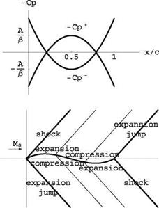
Using Ackeret formula one finds C + — ±20/в and C- — 0 . This is shown in Fig. 15.32 at a — 0. The flow features are displayed in Fig. 15.33 (shocks, charac­teristic lines, expansion shocks).

x

c

Fig. 15.32 Cp distribution on the half double wedge at a — 0

Aerodynamic Coefficients

Подпись: 4 в Supersonic Flow (Mo &amp;gt; 1, в = JM( — 1) Подпись: dx c Подпись: в
Supersonic Flow (Mo &amp;gt; 1, в = JM( — 1)

At a = 0 , the drag coefficient (Cd)a=0 is given by

Supersonic Flow (Mo &amp;gt; 1, в = JM( — 1) Подпись: 4 в Подпись: c x dx d '(x)xdx 0 c c Подпись: 4 в Подпись: 1 2
Supersonic Flow (Mo &amp;gt; 1, в = JM( — 1)

and moment coefficient (Cm, o) 0 by

Подпись: 0Подпись: 4 & в ~4Supersonic Flow (Mo &amp;gt; 1, в = JM( — 1)&

Static Equilibrium About an Axis

If an axis is located at the leading edge, x = 0, the equilibrium angle aeq corresponds to a zero moment coefficient, i. e.

Подпись: & aeq = -~4 Cm, o(aeq) = (Cmo)a=0 – 2в = 0,

The equilibrium is stable because dCm, o/da < 0.

2-D Inviscid, Linearized, Thin Airfoil Theories

15.8.1.1 Incompressible Flow (Mo = 0)

Profile Geometry

Consider a half-double wedge profile of chord c of equation

f + (x) = d(x) + 1 e(x) = 0x, 0 < x < §
f + (x) = d(x) + §e(x) = 0(c – x), § < x < c

1

f (x) = d(x) – §e(x) = 0, 0 < x < c
See Fig. 15.30. The camber d(x) and thickness e(x) distributions are given by

d(x) = 1 (f+(x) + f-(x) = §0x, 0 < x < §
d(x) = 1 (f + (x) + f-(x) = 10(c – x), § < x < c

e(x) = f+(x) — f-(x) = 0x, 0 < x < §
e(x) = f +(x) — f-(x) = 0(c — x), § < x < c

Fourier Coefficients

The expressions of the Fourier coefficients A0 and An in the expansion of the vorticity for an arbitrary profile are

z/c

в/2

0.5

Fig. 15.30 Half double-wedge geometry

1 п. 2 n.

A0 = a — d [x(t)]dt, An — d [x(t)]cosntdt

п о п о

A0 and A2 is given by

Ao — a — — dt + ^ ^—— ) dt[ — a

A1 is given by

22 0 п 0 2 0 2 A1 — costdt + — costdt — {1 — (—1)} — 0

п 02 п 2 п 2 п

A2 is given by

2 2 0 п 0 2 0 A2 — – — cos2tdt + — — cos2tdt — — — {0 — (—0)} — 0

2-D Inviscid, Linearized, Thin Airfoil Theories Подпись: x/c

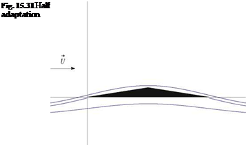
The incidence of adaptation aadapt is such that A0 — 0. Here we have aadapt — 0. See Fig. 15.31.

Definition of Aerodynamic Center

The aerodynamic center is the point about which the moment of the aerodynamic forces is independent of a.

Aerodynamic Coefficients

The aerodynamic coefficients C;(a) and Cm, o(a) are given in terms of the Fourier coefficients

Подпись:Cl (a)

Cm, o(a) —

Equilibrium of the AMAT09

15.7.3.1 Airplane Aerodynamic Center and Static Margin

The aerodynamic center is given by

Подпись: xa.c. Iref

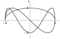
Подпись: Fig. 15.29 First three modes of circulation representation Equilibrium of the AMAT09

1.124

= = 0.287 = 28.7/100

C 3.912 ‘

da

The static margin SM is

SM = Xac – Xcg = 0.287 – 0.227 = 0.06 = 6/100

lref lref

15.7.3.2 Equilibrium Condition and Static Stability

The moment coefficient at the center of gravity, CM, c.g.(a, tt) is given by

Xc

См,с. д.(а, tt) = Cm, o (a, tt) + Cl (a, tt)

lref

CM, c.g.(a, tt) = -1.124a – 0.625tt – 0.138 + 0.227(3.912a + 0.626tt + 0.844) One finds

CM, c.g.(a, tt) = -0.236a – 0.483tt + 0.054

The slope of the CM, c.g. is negative. The equilibrium is stable.

At equilibrium CM, c.g. = 0, hence

a. eq (tt) = —2.064tt + 0.229

15.7.3.3 Top Speed

The top speed is obtained for tt = 7.6° = 0.1326 rd. The corresponding value of

aeq is

aeq = -2.060.1326 + 0.229 = -0.0448rd = -2.6°

The top speed, given that Aref = 2.225 m2, p = 1.2kg/m3 is such that the lift balances the weight

12

2 pUeqArefC L, eq — Mg

Подпись: U2 eq Подпись: 17.1 m/s

Equilibrium of the AMAT09

But CLeq = 3.912(-0.045) + 0.626(0.1326) + 0.844 = 0.751 One finds

15.8 Solution to Problem 8

Prandtl Lifting Line Theory

15.7.2.1 Vortex Sheet Characteristics

The conditions < u >=< w >= 0 on the vortex sheet behind a finite wing result from

• the continuity of pressure across the vortex sheet (a fluid surface),

• the tangency condition along the surface, respectively.

The existence of induced drag for a wing in incompressible, inviscid flow results from the non-zero components of v and w near the vortex sheet in the Trefftz plane, far downstream, where u = 0 (the pressure is back to the undisturbed value). The kinetic energy associated with v and w is not recoverable. There is more kinetic energy out of the control volume than into the control volume as shown by the application of the Steady Energy Equation. This excess kinetic energy comes from the work of the thrust that balances the drag.

15.7.2.2 Circulation Representation

The circulation is represented by a Fourier series

■ Г[y(t)] = 2Ub Z“=1 An sin nt
y(t) = -§ cos t, 0 < t < n

The first three modes with unit coefficients A1 = A2 = A3 = 1 are shown in Fig. 15.29.

15.7.2.3 Efficiency Factor

As seen in class, the definition of the Efficiency Factor e in terms of the Fourier coefficients is

Prandtl Lifting Line Theory

1

– = 1 + 2

e

+——- +n

Given that the wing loading is symmetrical, only the odd modes are present. Since the “simplest” wing is assumed for the AMAT09 wing, only modes 1 and 3 are non-zero

Подпись: 1 - = 1 + 3 e Подпись: 1 095 Prandtl Lifting Line Theory1.053, ^ = 0.132

At

Furthermore, the mode 1 amplitude is related to the lift coefficient by

Подпись:Cl = nAR Ai, ^ Ai =

The results for the three phases of flight are

• take-off: a = 18°, Cl = 2.5, ^ A1 = 0.141 , ^ A3 = 0.019

• top speed: a = -3°, Cl = 1.0 , ^ A1 = 0.056 , ^ A3 = 0.007

• power-off descent: a = 4°, Cl = 1.6 , ^ A1 = 0.09 , ^ A3 = 0.012

Supersonic Flow (Mo > 1, в = yjM^ — 1)

Pressure Distribution and Flow Features

The pressure coefficients are given by the Ackeret formulae

C = 7 (л (1 – 6 7 +6 ?) – a)

C – = – в (A (1 – 67 +677) – a)

The plot of – C + and – C – versus x for this airfoil at a = 0 is seen in Fig. 15.27. See sketch of the flow at a = 0 (shocks, characteristic lines, expansion shocks), Fig. 15.28.

Static Equilibrium About an Axis

Подпись:2a 1

Cm,1 (a) = iCm, o) a=0 – ^ + 7 Cl(a)

Supersonic Flow (Mo &amp;gt; 1, в = yjM^ — 1)Fig. 15.27 Pressure coefficients on the thin cambered plate at zero incidence

Fig. 15.28 Flow field past the thin cambered plate at zero incidence

, . 4 c, x dx 4 A 1 2

Подпись:(‘Cm, o a_0 = d'(x) = (1 – 6£ + 6£2)£d£ = 0
a=0 в 0 c c в 0

Hence the moment about the mid-chord reduces to

2a 1 4a

Cm, 1 (a) = — + 2 – = 0

Any value of a satisfies the equilibrium requirement. The equilibrium is neutral.

2-D Inviscid, Linearized, Thin Airfoil Theories

15.7.1.1 Incompressible Flow (Mo = 0)

Cambered Plate Geometry

Подпись: x d (x) = Ac c
2-D Inviscid, Linearized, Thin Airfoil Theories

Given the thin cambered plate equation

one calculates d'(x) to be

Подпись: x - 6 + 6 Подпись: c2-D Inviscid, Linearized, Thin Airfoil Theories

Подпись: where £ = c. d'(x) = 0 for f 2-D Inviscid, Linearized, Thin Airfoil Theories

d'(x) = A 1

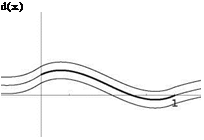
Fig. 15.25 Thin cambered d(x)

2-D Inviscid, Linearized, Thin Airfoil Theories Подпись: x c
2-D Inviscid, Linearized, Thin Airfoil Theories

plate

Fourier Coefficients

The Fourier coefficients A0, A1, A2,…, An for this thin cambered plate are obtained from the equation

d'[x(t)] – a = — A0 + ^ An cos nt

n=1

Changing variable from x to t in d'(x) yields

d'[x(t)] = A ^ 1 — 3(1 — cos t) + 3(1 — cos t)2^

/ 1 3 2 A

= A — 2 + 2 cos21 = — (1 + 3cos2t)

2-D Inviscid, Linearized, Thin Airfoil Theories

where we have made use of the identity cos21 = (1 + cos 2t )/2. Substitution in the above equation provides by simple identification all the Fourier coefficients

A3

Ao = a — , A1 = 0, A2 = A, A3 = ••• = An = 0, n > 3

From the result for A0 one finds aadapt = A.

Sketch of the flow at the incidence of adaptation is in Fig. 15.26.

Definition of Aerodynamic Center

The aerodynamic center is the point about which the moment of the aerodynamic forces is independent of incidence.

Fig. 15.26 Thin cambered plate at incidence of adaptation and some streamlines

Подпись: d(x) Aerodynamic Coefficients

2-D Inviscid, Linearized, Thin Airfoil Theories

The aerodynamic coefficients C;(a), Cm, o(a) and Cm, a.c. are all expressed in terms of the Fourier coefficients, i. e.

n 3n

Cm, a.c. = ~~r (A1 — A2) = A

4 16

Static Equilibrium About an Axis

The change of moment formula gives the aerodynamic moment coefficient at the mid-chord, x = 2

Подпись:n 5 A 1 A n A

a — + 2n a — = a +

2 8 2 4 2 8

The equilibrium angle aeq is such that Cm 1 (aeq) = 0. Hence

A

2-D Inviscid, Linearized, Thin Airfoil Theories

aeq = —8

Equilibrium of the Aggie Micro Flyer

15.6.3.1 Airplane Lift and Moment Curves

The equilibrium code calculates the lift and moment coefficients for the complete configuration at low incidences to be:

CL (a, tt) = 4.391a + 0.757ft + 0.928
См, о(а, tt) = -1.733a – 0.686ft – 0.267

We will use this linear model, even for take-off conditions.

Definition of the aerodynamic center:

The aerodynamic center is the point about which the moment is independent of incidence.

Подпись: xac Iref Подпись: dCM,o d a dCi d a Подпись: 1.733 4.391 Подпись: 0.395

As seen in class, the location of the aerodynamic center is given by

That is xac = 0.632 m.

Given that xcg = 0.503 m, the static margin is

SM = Xac – Xcg = 0.08

Iref

a static margin of 8 %.

15.6.3.2 Take-Off Conditions

The longitudinal equilibrium equation for the moment reads

CM, cg(a) = См, о (a) + Cl (a) = 0

Iref

This equation represents the transfer of moment from the nose O of the aircraft to the center of gravity and states that the moment of the aerodynamic forces at the center of gravity must be zero.

The main wing lift curve is given by

CLm = 4.927a + 1.388

Since the take-off lift coefficient for the main wing is (CLm)t-o = 2.7, the inci­dence can be found to be (a)t-o = 0.266rd = 15.3°.

Find the tail setting angle at take-off is then given by the equilibrium equation as -0.686tt – 0.728 + 0.314(0.757tt + 2.096) = 0

which gives tt = -0.156rd = -8.9°.

Equilibrium of the Aggie Micro Flyer Equilibrium of the Aggie Micro Flyer

The location of the center of pressure is given by

Hence, xcp = 0.502 m.

The global lift coefficient can now be found to be

CL = 4.391 0.266 – 0.757 0.156 + 0.928 = 1.978 By definition we have

(am + at )CL = am CLm + atCLt

Here am = 0.709 m2 and at = 0.254 m2. Solving for CLt gives

CLt = -0.04

The tail lift coefficient at take-off is close to zero (within our linear model accuracy).

15.7 Solution to Problem 7