Category Theoretical and Applied Aerodynamics

Equilibrium of the Glider (3-D Incompressible Flow)

14.1.3.1 Glider Effective Aspect Ratio

As a glider (engine off), the glider has the following lift and moment coefficients in terms of the geometric angle of attack a (rd) and tail setting angle tt (rd):

Cl (a, tt) — 5.3a + 1.56 + 0.5tt
Cm,0 (a, tt) — —1.7a — 0.43 — 0.45tt

Find the effective aspect ratio AR of the glider (wing+tail), assuming ideal loading.

14.1.3.2 Equilibrium Angle of Attack

Find aeq (tt) for the glider, given that ^ — 0.29. Hint: the equilibrium of the moment corresponds to

Подпись: CM,0(aeqПодпись: , tt) — 0x

, tt) + CL (aeq

lref

Find the angle of attack aeq and the corresponding setting angle of the tail tt for Cl — 1.9.

14.1.3.3 Landing Speed

At sea level, p — 1.2 kg/m3, g — 9.81 ms-2, find the landing speed, given that the total mass m — 15 kg, the maximum lift coefficient (CL )max — 1.9 corresponding to the reference area Aref — 0.68 m2. Hint: use the equilibrium equation in the direction perpendicular to the flight path.

Lifting Line Theory

14.1.2.1 Flow Model

Explain, in simple terms, how an inviscid flow model, Prandtl Lifting Line theory, can account for a drag in the flow past a finite wing. Use arguments such as Joukowski Lift theorem with a sketch, or energy equation.

Give the expressions for the lift coefficient CL and induced drag coefficient CDi of an arbitrary wing, in terms of the Fourier coefficients A1, A2,…, An. The area of reference, Aref = S is the wing area.

14.1.2.2 Non Singular Lift Distribution

To lower the risks of tip vortex encounter in airport traffic associated with intense vorticity( dy D = ±сю), the new generation of airplanes is required to have weak tip vortices. This is achieved by enforcing a Г distribution such that dT (±|) = 0.

Подпись: Г [y (t)] Подпись: = 2Ub (A1 sin t + A3 sin 3t) y (t) = ~b cos t Подпись: 0 < t < n

For a given CL = 0, a distribution that satisfies this condition and has a low induced drag is a combination of modes 1 and 3:

Find the relation between A1 and A3 that satisfies dL (-1) = 0 (by symmetry, the other condition will be satisfied).

Make a graph of the corresponding distribution Г(y) or T(t).

14.1.2.3 Drag Penalty

For a given CL (at take-off), find the penalty in induced drag for a given aspect ratio AR compared to the elliptic loading. Work the answer formally (do not plug in numbers).

Find the efficiency factor e — (1 + J)-1.

Problems

14.1 Problem 1

14.1.1 Thin Airfoil Theory (2-D Inviscid Flow)

14.1.1.1 Quiz—Answer by Yes/no

• in subsonic flow, does the aerodynamic coefficient given below depend upon the small parameters:

Aerodynamic coefficient e/c d/c a

Ci

Cm, o

Cm, ac

Cd

• in supersonic flow, does the aerodynamic coefficient given below depend upon the small parameters:

Aerodynamic coefficient e/c d/c a

Ci

Cm, o

Cm, ac

Cd

14.1.1.2 Lift Coefficient

A thin profile with parabolic camber d = 0.02 is set at angle of attack a = 5°. Find the lift coefficient Ci in incompressible flow. Find the lift coefficient in compressible flow at M0 = 0.7. Hint: use linear correction method.

© Springer Science+Business Media Dordrecht 2015

J. J. Chattot and M. M. Hafez, Theoretical and Applied Aerodynamics,

DOI 10.1007/978-94-017-9825-9_14

14.1.1.3 Drag Coefficient

If the drag coefficient of the same profile at a = 0 and M0 = 1.4 is (Cd)м0=1.4 = 0.02, find the drag at M0 = 2. (hint: look at the definition of (Cd)a=0). What will the drag be at M0 = 2. if a = 5°? What is the drag coefficient at M0 = 0.7?

14.1.1.4 Equilibrium About an Axis

Give the definition of the aerodynamic moment coefficient Cm, o in terms of the dimensional quantities.

If the profile is attached to a vertical axis located at x = 0 (nose of profile), write the equation of equilibrium that will give the equilibrium angle of attack aeq. Find aeq, and sketch the profile at equilibrium. Is the equilibrium stable?

Electronic Analog Computers: Networks Versus Tanks

The analogy between an electrical system and a mechanical system is well known. For example, a mass-spring damper system is equivalent to a circuit of resistors, capacitors and inductors, governed by the same second order ordinary differential equation and can be solved on an analog computer using summation and integration elements with continuous real time simulation and low power requirement. Systems of two degrees can be simulated via solving two coupled differential equations and coupling partial circuits. Accuracy is limited however, due to the noise in the circuits.

Analog computers were used in aeronautical industry in the fifties and sixties (before digital computers took over). Evolutionary partial differential equations can be reduced to systems of ordinary differential equations (continuous in time) via method of lines, where space derivatives are approximated with finite differences. Examples of heat and wave equations can be solved using analog computers with real time simulation. Stiff and nonlinear equations can also be treated using hybrid computers (see Ref. [19]). New ideas in this field are promising, for example the neural network systems [20].

13.4 Concluding Remarks

In this chapter, we discussed flow analogies including the Hele-Shaw cell, hydraulic analogy and electric analogy. Analog computer is also briefly covered. Other analo­gies exist. For example flowing foam, (a foam is a mixture of gas with a liquid at constant mass ratio).

Let p be the mass concentration of the gas and 1 – p that of the liquid, then the specific volume of the foam is

Подпись: 1 P (13.85)

where p and о are the densities of the gas and the liquid component, respectively.

Assuming the expansion of the gas in the bubbles to be isentropic and p > p/о, hence

Подпись:Electronic Analog Computers: Networks Versus Tanks(13.86)

Подпись: 2 2 Подпись: p dp = P P0 P Подпись: 2 Electronic Analog Computers: Networks Versus Tanks

The speed of sound c2 = dp/dp = pdp/dp = pc2, and from Bernoulli’s law, the velocity is given by

Подпись: c Подпись: q = M c Подпись: (13.88)

Hence,

Flowing foams and cavitating liquids are closely related. For more details see Oswatitsch [9].

In this regard, it is of historical interest that the analog solution of the torsion problem of a bar was proposed by L. Prandtl, and used by G. I. Taylor, two giants of fluid mechanics. An opening in the plane that has the same shape as the cross­section of a torsion bar covered with homogeneous elastic membrane, such as a soap film, under pressure on one side will have a lateral displacement satisfying the same equation as the Prandtl torsion stress function. Prandtl’s membrane analogy is discussed in many strength of materials books, see for example [21].

Sobieczky’s Rheograph-Transformations

Sobieczky [17] used Busemann normalized hodograph plane, where ф and ф (potential and stream function) can be written as Beltrami equations:

дф дф

dq = ±K (q) дв

(13.83)

дф дф

дв=K (q) Tq

(13.84)

where q (and K) are functions of the local Mach number. The above linear system for generalized potentials, is hyperbolic for M > 1 (q (M) > 0) and elliptic for M < 1

(q(M) < 0).

For transonic plane flow, the values of ф and ф for the subsonic and supersonic parts are connected along the transformed sonic line, the axis q = 0.

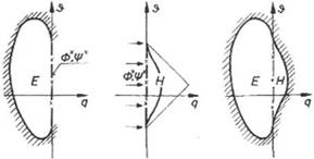
Let, ф, ф(q = 0, в) = ф*, ф* (в). For the elliptic region, ф* and ф* are used to complete the formulation of an elliptic boundary value problem, and for the hyperbolic domain, ф* and ф* are initial values which describe the solution of the above equations in a triangular region of dependence. It should be mentioned that Sobieczky’s formulation of transonic boundary value problem is different from the well known Tricomi problem, since there is no prescribed boundary in the hyper­bolic region.

In the elliptic domain (q < 0), the elliptic system does not change its nature by conformal mappings. Sobieczky introduced several mappings called rheograph- transformations to facilitate the solution of the equations in the elliptic domain. He used electric analogy and conducting papers which have to be inhomogenized to vary the local conductivity to simulate the coefficient K in the governing equations.

On the other hand, the solution of the hyperbolic equations can be found by series expansion or by the method of characteristics, where the computation starts from the given sonic line.

In passing, for near sonic flows, where the mach number is close to one in the whole flow field, Sobieczky replaced q (M) and K (M) by the first term of their series expansions around M = 1. The governing equations take now the form of generalized axially symmetric potential equations treated by Weinstein, thus Sobieczky obtained

Подпись: Fig. 13.6 Formulation of a transonic boundary value problem (from IUTAM Symposium Transonicum II, 1976, Springer Verlag, with kind permission of Springer)
Sobieczky’s Rheograph-Transformations

exact solutions in closed form which are identical to the solutions of the Tricomi equation.

The electric analogy together with the method of characteristics were used suc­cessfully to design supercritical wing sections as well as to design transonic cascades. For a given upstream velocity, the elliptic boundary value problem is defined and an analog model can be produced. Continuation of the analog model beyond the sonic line, using numerical methods, allows the calculation of the dependent supersonic flow region and hence the airfoil contour, see Fig. 13.6.

Later, Sobieczky introduced the method of fictitious gas, where the density is modified in the supersonic region, and the flow field is solved to produce the sonic line. The elliptic flow field with the sonic line are used to construct shock free airfoil via continuation based on the method of characteristics and the actual density in the supersonic region, to produce the contour of the airfoil adjacent to the supersonic flow. See Ref. [18] for more details (Notice that the direct extension to three dimensional flows over a wing leads to unstable calculations) (Fig. 13.6).

Analog Study of Three-Dimensional Flows

In general, the study of lifting surface problems can be performed with the help of electric tanks.

The low and high aspect ratio (AR) wings are of special interest since the formu­lation will reduce to two-dimensional problems.

In the case of slender wings and slender bodies at angle of attack, the flow can be decomposed into axial and normal components. The cross flow at the end section can be easily studied by electric analogy (as a special case of two-dimensional flows with a = 90°) using polar coordinates.

Analog Study of Three-Dimensional Flows Подпись: (13.74)

On the other hand, the lifting line theory for high AR wings can be studied using the Trefftz plane. The Prandtl integro-differential equation is given by

where the downwash at the lifting line is given by

Analog Study of Three-Dimensional Flows(13.75)

Подпись: 1 dp 2 dz . Notice that Г(-Ь) = Г(Ь) = 0 and 7b dГ(п) = 0. A potential function can be

introduced in the Trefftz plane such that Г(у) = 2^> and w Now, p is zero outside the span (-b, b), and in between

Подпись:Подпись: )Analog Study of Three-Dimensional Flows(13.76)

Also, p need only to be considered in a half-plane since p(y, -z) = – p(y, z).

The boundary conditions along the axis can be simulated using a distribution of electrodes to impose the above mixed boundary condition as well as the Dirichlet condition, in a plane tank of large dimensions.

Nonlinear local lift coefficient in the neighborhood of maximum lift can also be considered using successive approximations.

Moreover, wind tunnel wall effects can be readily shown using dp/dn = 0 on solid walls and p = const. in open section, where the pressure is constant across the wall boundaries.

Analog study of propeller’s performance following Goldstein’s analysis [16] is also possible. The potential of the velocity induced by the trailing vortex sheets satisfies the equation

Подпись: (13.77)1 д дф 1 д2ф д2ф

r dr dr + r2 дв2 + дz2

where the z-axis coincide with the propeller axis. If the propeller has p blades, the trailing vortex system is composed of p helicoids of geometric pitch h = 2nw/w, where w is the translation velocity along the z-axis and w is the angular speed of rotation.

The equation of these helicoidal surfaces is defined by z k

в – = 2п, k = 0, 1,…p – 1, 0 < r < R (13.78)

A P

Analog Study of Three-Dimensional Flows Подпись: (13.79)

where A = w/(wR), R is the radius of the propeller. The potential equation can be written in terms of £ = r/R and Z = в – z/x as follows

Moreover, the periodicity of the field with respect to £ (period 2п/p) and the antisymmetry of ф with respect to a cut, allow the domain for ф to be reduced to a sector 0 < Z < n/p.

The boundary conditions are

Подпись: (13.80)Подпись: (13.81)ф = 0 at Z = 0, £ > 1

Подпись: 2 ’ Подпись: Z = 0, 0 < £ < 1 Подпись: (13.82)

ф = 0 at Z = п/p, £ > 1

The circulation is calculated as in the lifting line problem assuming that the airfoil section £ of the blade has the same properties as that of infinite aspect ratio with a wind velocity vW+W, at an effective angle of attack (a – 6a), where a is the geometric angle of attack and 6a is the induced angle.

Imposing the periodicity condition is of interest also in the study of cascade problems.

Analog Study of Supersonic Conical Flows

The governing equation of the perturbation potential for linearized three-dimensional supersonic flow is given by

Подпись:2 д2ф д2ф д2у

дх2 ду2 dz2

where в2 = M2 – 1.

When the flow is conical, p depends only on two variables as follows. Let

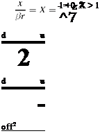
Подпись: (13.70)у = r cos в, z = r sin в, x = firX

then, any of the three velocity components, u, v, w depend only on в and X. For X = cos £, a Laplace equation is obtained for the flow interior to the mach cone

(13.71)

For X > 1 (exterior of the mach cone), with X = cosh £, the wave equation is obtained

For more details, see Stewart [13].

Analog Study of Supersonic Conical Flows Analog Study of Supersonic Conical Flows
Подпись: i в

To study the flow inside the Mach cone, the complex variable Z = gel6, where

Either u, v,w may be identified with the electrical potential in a plane circular tank.

Germain [14] analyzed in detail the analog representation for a flat plate inside the Mach cone. he also studied wings with different cross sections and with dihedral angles. The study of wings in supersonic flow regime, steady and unsteady, was carried out by Enselme [15].

Д дф д дф дх р’дх + дг ‘"Hr = 0   (13.61)   and   д Щ – + д = 0 дх рг дх дг рг дг   (13.62)   These equations can be compared to the equations governing the electrical po­tential in a conducting medium of varying thickness. The depth of the conducting material will be proportional or inversely proportional to рг, depending on whether ф or ф is simulated. In the first case, inclined tank can be used to simulate flow around streamlined bodies of revolution, convergent wind tunnel ducts and axially symmet­ric air intakes. For the representation of the stream function, a tank with hyperbolic bottom can be constructed where the depth varies as 1/y, see Ref. [12].   13.3.3 Hodograph Tank   In the hodograph plane, the velocity potential ф and the stream function ф, of com­pressible fluid flow are related by the following equations   д 1 дф д ( р дф дд ррд (1 – M2) дд + дв р0д дв °   (13.65)   and   (13.66) &nbsp

Д дф д дф дх р&#39;дх + дг &#39;&amp;quot;Hr = 0 &amp;nbsp; (13.61) &amp;nbsp; and &amp;nbsp; д Щ - + д = 0 дх рг дх дг рг дг &amp;nbsp; (13.62) &amp;nbsp; These equations can be compared to the equations governing the electrical po&#173;tential in a conducting medium of varying thickness. The depth of the conducting material will be proportional or inversely proportional to рг, depending on whether ф or ф is simulated. In the first case, inclined tank can be used to simulate flow around streamlined bodies of revolution, convergent wind tunnel ducts and axially symmet&#173;ric air intakes. For the representation of the stream function, a tank with hyperbolic bottom can be constructed where the depth varies as 1/y, see Ref. [12]. &amp;nbsp; 13.3.3 Hodograph Tank &amp;nbsp; In the hodograph plane, the velocity potential ф and the stream function ф, of com&#173;pressible fluid flow are related by the following equations &amp;nbsp; д 1 дф д ( р дф дд ррд (1 - M2) дд + дв р0д дв &#176; &amp;nbsp; (13.65) &amp;nbsp; and &amp;nbsp; (13.66) &amp;nbsp Подпись: (13.67)

these equations may be compared to the equation of the electric potential in a con­ductor, in terms of polar coordinates

It is possible to establish the correspondence with r = r (q) and h = h(q).

The electric tank may be constructed in a circular form, where the center cor­responds to the origin of the (q, $)-plane. The tank radius is limited to a value corresponding to M slightly less than one (for Mach = 1, the depth is infinite). The image of uniform flow is given by a singularity placed at a point, the distance of which from the origin corresponds to the magnitude of the velocity of the uni­form stream at infinity. The singularity is represented in the tank by two electrodes, properly chosen.

To determine the form of the wing section which corresponds to the hodograph chosen, the following relations are used

cos в sin в

dx =——– d ф, dy =——— d ф (13.68)

qq

where x and y are obtained via simple integration.

Analog Representation of Circulation Around Lifting Airfoils

In this case, the velocity potential is not single-valued function. The analogy in which it is identified with an electric potential is not simple since cuts must be provided in the conductor in order to make the electric potential single-valued.

Instead, the stream function of the fluid flow, which is continuous, will be iden­tified with an electric potential. However, to give the circulation around the body a prescribed value, the model must function as an extra electrode. it must be connected through an adjustable resistance, R, to one of the poles (chosen to give the correct sign of Г). It is possible, however, to establish a “cut” in the electric field, which can be chosen along an equipotential line, extending outward from the surface of the body. This cut is realized in the electric tank by two auxiliary electrodes separated by a thin insulating strip. The potential difference between theses two electrodes corresponds to the value of the circulation (the flux crossing the cut must be conservative).

Studies of interaction problems using combination of airfoil sections are possi­ble. Also, airfoils with flaps and hinged leading edges as well as slots have been considered. Since conformal mappings satisfy the Cauchy-Riemann equations, it is feasible to construct electric analog of conformal transformation of an airfoil (or any closed region) onto a circle.

Analog study of airfoil cascades is based on representing the periodicity of the field.

Analog Representation of Circulation Around Lifting Airfoils

Electric Analogy

This analogy is based on the relation between the equation governing the electrical potential in a conductor and the velocity potential of fluid flows. In the absence of interior sources within the conductor, the electric potential ф is governed by

Подпись: (13.56)V. (aVф) = 0

where a is the conductivity.

For homogeneous conductors with constant conductivity, the above equation reduces to the Laplacian

Подпись: (13.57)V2 ф = 0

which is the same equation for the velocity potential of inviscid, incompressible fluid flow, even for unsteady problems (for example oscillating wing).

For two-dimensional models, it is possible to represent variable conductivity by a model having variable thickness. In this case, the electric potential is governed by

Подпись: д д хПодпись: =0Electric Analogy(13.58)

Moreover, one can introduce a stream function ф, such that

Electric Analogy Electric Analogy

The equation for ф is given by

The Dirichlet and Neumann boundary conditions are simple to reproduce in the electrical model. For ф = const., the boundary is covered by an electrode which is raised to the potential level specified. For дф/дп = 0, the boundary is insulated (i. e. no electric current crosses the boundary).

The conducting media can be a weak electrolyte contained in a tank leading to “electrolytic basin” technique metallic plates or special conducting papers are also used.

Notice, for compressible (subsonic) flow studies, the height distribution must be adjusted iteratively to be related to the density distribution Which is unknown a priori).

For details of the apparatus and the experimental techniques, see Malavard [12]. In the following, some applications are discussed.