Category UNSTEADY AERODYNAMICS, AEROACOUSTICS AND AEROELASTICITY OF TURBOMACHINES

Theoretical Model

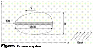
Подпись: Figure /. Reference system

The systems discussed will have one degree-of-freedom. They consist of a rigid body, whose position can be described by a single coordinate. The body has a length distribution b(z) in the slreamwise coordinate x, as shown in Fig. 1.

The height of the system is h; f(z) is the local position of the leading edge line. The gust is applied in a direction normal to the plane (ж, z). The fbw model will be potential, with a free stream velocity V in the x-direction. The fbw will be inviscid, subject to small perturbations, created by oscillatory gusts of reduced frequency k.

The gust response will be modeled in the frequency domain by the admit­tance, that we indicate with H(k). In wind engineering, this quantity is often indicated by x2. For a more detailed discussion, see Filippone and Siquier, 2003, Filippone, 2003.

Подпись: H(k) Подпись: m F(k 0) Подпись: (1)

For complete clarity, the admittance is a transfer function defined as the ratio between the loads under unsteady forcing of finite frequency к and the quasi steady loads, e. g. loads with infinitely large wavelength:

where F is a generic load (lift, side force, yaw moment, etc.). With the defi­nition Eq. 1 we have H —> 1 as к —» 0. This definition is coherent with that given originally by Davenport (1961). A result not conforming with this limit­ing value will not be considered correct. The definition of Eq. 1 is important, also because it is related in a straightforward way to the power spectra density:

PSD(k) ~ 2H’k) (2)

which does not require the Fourier transform of the system’s response in the ti me domai n.

In an earlier study (Filippone and Siquier, 2003), we proved that under the above conditions the admittance for side force (or lifting force) can be de­scribed by the following equation:

H(k) = I / r{z)Hx[r{z)k]e-iv{z)kdz (3)

h J h

Theoretical Model

where

C (k) = F (k) + iG(k). (5)

Theoretical Model Подпись: (6)

The quantities J0, J are Bessel functions of the first and second kind in the reduced frequency k

Подпись: V + Vg Подпись: 1 1 + Vg/V Подпись: (7)

and Г is the gamma function; A is the gust speed ratio, defined as

where Vg is the gust velocity in a frame of reference fixed with the ground, V is the velocity of the body. All the values of A can be considered, except the singular value obtained for V = —Vg (e. g. when the gust and the body are traveling in opposite directions with the same speed). The value A = 1 corresponds to a stationary gust, e. g. Vg = 0; A = 0 is a limit value obtained with Vg/V ^ ±ro, which is possible with a stationary body (e. g. V = 0) and a moving gust. Values of 0 < A < 1 are the most common in practical applications.

Подпись: b(z) (8) b № b (9)
Подпись: r(z) p(z) where b is the average body length.

Finally, two functions, appearing in Eq. 3 are two functions of the local body length

UNSTEADY GUST RESPONSE IN THE FREQUENCY DOMAIN

A. Filippone

UMIST

Department of Mechanical, Aerospace, Manufacturing Engineering Manchester M60 1QD United Kingdom a. filippone@umist. ac. uk

Abstract A theory has been derived to describe the unsteady response of arbitrary two­dimensional bodies in the frequency domain. The theory provides the values of the admittance for side force and yawing moment under sinusoidal gust condi­tions. This approach provides indirectly the power spectra density (PSD), which is often used to characterize systems in unsteady periodic conditions (Filippone and Siquier, 2003, Filippone, 2003). The fbw model is inviscid, with the as­sumption of small perturbations. Results are shown for a squared, a triangular, and a circular plate, as well as some road vehicles. The existence of critical damping is discussed for some cases.

1. Introduction

Lateral gusts have been known to affect the handling of many road vehicles, including large Sport Utility Vehicles (UV). Another example is vehicle pass­ing: at some speeds, this creates a destabilizing wave that can be attributed to a gust-like phenomenon. The destabilizing effect is a function of both the rela­tive speed and the relative size and inertial mass of the vehicles. A high speed train encountering a gust at the exit of a tunnel is another case considered crit­ical (Schetz, 2001). However, some gust events are outright violent. Recently (May 8, 2003), the US National Weather Service reported that straight-line winds were suspected of causing a freight train to derail in Kansas.

Laboratory experiments in this area of aerodynamics are scarce due to the intrinsic difficulty of creating gust conditions in the wind tunnel. In fact, lateral unsteady ft>ws of fixed frequency, shape and speed must be created along with the main wind tunnel ft>w. However, a limited number of studies exist. Bear – man and Mullarkey, 1994, studied the lateral gust response of a family of bluff

95

K. C. Hall et al (eds.),

Unsteady Aerodynamics, Aeroacoustics and Aeroelasticity of Turbomachines, 95-106. © 2006 Springer. Printed in the Netherlands.

bodies resembling road vehicles. These bodies are characterized by different after-body scant angles, from zero to 40 degrees.

Earlier on, Bearman, 1971a, and Bearman, 1971b, performed important experiments on fht plates and circular disks in turbulent and laminar fbw, and calculated the admittance for the drag force (or side force, in the present nomenclature) of these bodies. The systems were placed in a wind tunnel in a position normal to the incoming fbw. These plates were a particular case of bluff bodies, for which fbw separation plays a major role. Bearman’s paper discusses a number of fundamental issues, such as the general behavior of the admittance in turbulent fbw, and the theory used to correlate the wind tun­nel data (Vickery, 1965). Vickery’s experimental and theoretical work led to a semi-empirical relationship for the admittance of fht plates in normal turbu­lent fbw. This correlation is sometimes used to predict the admittance in wind engineering applications.

Howell and Everitt, 1983, considered a high speed train with two degrees – of-freedom (pitch and yaw), in order to identify the risk of a train overturning in high cross winds, and the effects associated to track-side structures and pas­sengers. Larose et al., 1999, have performed wind tunnel experiments to derive the frequency response of very large ships at sea. This study was aimed at pro­viding controls to large vessels at port. Data for aerospace systems could not be found in the technical literature, perhaps because wing controls are considered in terms of effectiveness, rather than admittance.

We will use a development based on an indicial approach, which, in spite of some underlying simplifications, is fast and powerful. This paper will discuss the properties of the admittance functions and their practical meaning.

The theory originates from a mathematical treatment of the results deter­mined by Drischler and Diederich, 1957, who considered sharp-edged travel­ing gusts past two-dimensional wings in a wide range of speeds. The theory allows the calculation of the admittance for the lift force (or side force, if the system is non lifting) and for the pitching moment (or yawing moment, re­spectively). This analysis does not take into account the structural inertia of the system.

Classical analyses in the frequency domain are due to von Karman and Sears, 1938 for the sinusoidal gust on the two-dimensional airfoil. However, it is more common to find analyses in the time domain, for example the classical works of Kussner, 1936, and Wagner, 1925, who derived basic transfer func­tions for the abrupt change in angle of attack (Kussner) and the response to a fixed sharp-edged gust (Wagner). See Leishman, 2000, for a full review.

Flutter Measurements

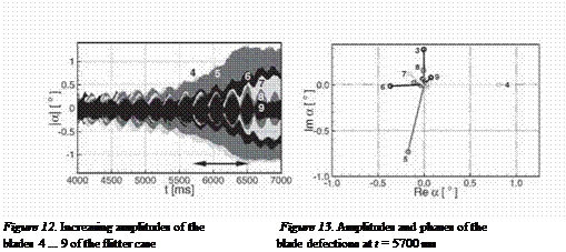
Increasing the vibration amplitude beyond a certain level in the "flutter case" the cascade starts with self-excited vibrations. Figure 12 plots the amplitude
of some blades versus time when the cascade was excited at a frequency of 177 Hz. After reaching a certain amplitude, the cascade start to vibrate at its eigenfrequency of 182 Hz. Then the excitation was turned down. While the cascade was vibrating in its eigenfrequency and was simultaneously ex­cited, beats are clearly visible. A Fourier analysis performed every 100 ms

Подпись: Figure 12. Increasing amplitudes of the Figure 13. Amplitudes and phases of the blades 4 ... 9 of the flitter case blade defections at t = 5700 ms
for sections of 819 ms (8192 time samples) leads to the complex amplitudes (amplitude and phase) and gives an insight into the vibration mode. (Figure 13 shows the results of a Fourier analysis started at 5700 ms.)

It is visible, that only some blades — namely blade 3 to 9 — were vibrat­ing with a significant amplitude. The phase between these blades remained constant over time, but there is no equal interblade phase angle between all blades visible. This may be caused by the cascades’s mistuning due to blades equiped with pressure taps and tubes as well as blades with unsteady pressure transducers.

2. Summary

Measurements of aerodynamic damping were performed for nearly identi­cal transonic fbw cases, but for different reduced frequencies. For the lower reduced frequency the cascade was proven to be aerodynamically unstable. Besides the front shock impulse and pressure side’s channel shock impulse this unstable case was characterized by a strong channel shock impulse near suction side’s trailing edge. While the effects of the front shock impulse and pressure side’s channel shock impulse canceled out each other, the impulse of the channel shock near the trailing edge on the suction side had a significant inflience on stability. Increasing the forced vibration amplitude, the cascade started with self-excited vibrations.

Evaluation of the Aerodynamic Damping

Due to the fact that the cascade in the "flitter case" remains aeroelastically stable for very small pitching amplitudes (below 0.2°) it was possible to ob­tain unsteady pressure distributions caused by forced pitching vibrations of the blades in each traveling wave mode — in the same manner as the larger amplitudes in the "transonic reference case".

Following the "aerodynamic aproach" the measured unsteady pressure val­ues and vibration signals were recorded. A Fourier transformation yields the first harmonic of the pressure which is related to the pitching motion of that blade і according to eq. (2) by

Подпись:Подпись: (6)p(t) = p COS(Ш — І (7/t. + Ф) .

The unsteady pressure coefficient is defined as

a =_______ I____

P 6: (p, i – Pt )

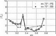
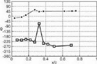
where p — p ехр(у’Ф) is the first harmonic of the unsteady pressure. The Cp-distribution for the interblade phase angle (IBPA) Of. = 72° is shown in Figure 8a for the "transonic reference case" and in Figure 8b for the "flitter case". Tn order to avoid numerical inaccuracies due to the discrete Fourier transformation, the sinusoidal vibration signals were Fourier transformed as

Evaluation of the Aerodynamic Damping

u* = 0.362

Evaluation of the Aerodynamic Damping


u* = 0.289

Evaluation of the Aerodynamic Damping


Evaluation of the Aerodynamic Damping

Figure 8b. Unsteady pressure coefficient Cp for the ІВРЛ at = 72° of the flit­ter case (magnitude at the top, phase at the bottom)


Evaluation of the Aerodynamic Damping

Figure 8a. Unsteady pressure coefficient C’p for the IВ PA о = 72° of the transonic reference case (magnitude at the top. phase at the bottom)

well. Arranging the Cp-distribulions of each IB PA side by side, Figures 9a and 9b are obtained.

It can be seen from the pressure distribution of both cases, that the impulse response of the front shock is visible on the suction side at xjc 0.28 in the "transonic reference case" and at xjc « 0.32 in the "flitter case". Comparing the channel shock of the "transonic reference case" with the "flitter case", the impulse response on the pressure side is visible at xjc se 0.17 in the "transonic reference case" and at xjc % 0.32 in the "flitter case". The impulse response of the channel shock is only visible at the suction side at xjc > 0.75 for the "flitter case".

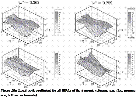
The contribution of the locally acting aerodynamic forces due to the un­steady pressure to the aerodynamic damping of the cascade is given by the lo­cal work coefficient, i. e. the dimensionless work per unit arc length performed by the fLiid on the blades. It is obtained by the integration with respect to time t over one period T of the pitching motion a(t) and yields

w*(0 = / ср(Л’t) ~i] [№)-П)) x n(0]3<it./o °

Evaluation of the Aerodynamic Damping

Figure 9a. Unstcady pressure coefficient

C„ for all IBPAs of the transonic ref. case (top: pressure side, bottom: suction side)


Figure 9b. Unsteady pressure coefficient Cp for all IBPAs of the flitter case (top: pressure side, bottom: suction side)

where (f(0—f0) is the dimensionless vector from the pitching axis to a surface point at the dimensionless arc length £ and n(£) as the outward normal vector on that surface point. The subscript "3" denotes the radial component of the cross product. For the pitching motions of rigid blades in a given traveling wave mode, the local work coefficient is dependend on the amplitude of the aerodynamic moment due to the first harmonic of the unsteady pressure on a surface location, the (harmonic) pitching motion of that blade, and the phase between them to a local stability parameter. It is negative for stable and positive for unstable aerodynamic conditions.

In order to assess the aerodynamic stability of the two transonic cases in detail, the local work coefficient u;*(£) is used to acquire an insight into the local contributions of the unsteady pressure at each measuring location —es­pecially at locations, where considerable pressure fbetuations appear due to the shock movement, which is caused by the blade vibration. Regarding Fig­ure 10a for the "transonic reference case" and Figure 1 Ob for the "flitter case", the following aspects are recognizable:

■ The contribution of the high unsteady pressure level on the leading edge stabilizes the pitching motion of the blade for all traveling wave modes. On the suction side, the local work coefficient is nearly constant, on

Подпись:
Figure 10b. Local work coefficient for all IBPAs of the flitter case (top: pressure side, bottom: suction side)

the pressure side, the stabihzing effect of the leadling edge for traveling wave modes with an ШРА between 180° and 360° is higher then for IBPA between 0° and 180° .

■ The high unsteady pressure level due to the front shock is stabilizing the motion in all travelling wave modes except for those with an IBPA between 288° and 360° for the "transonic reference case". Here the local work coefficient is near zero, that means no significant contribution to stability or instability. In contrast to that, the shock impulse of the front shock stabilizes only for the IBPA between 36° and 180° in the "Hiller case" — for the other traveling wave modes it destabilizes.

■ Comparing the channel shock impulse on the pressure side, in both cases the largest contribution to instability occurs in the vicinity of an ЮРА of 126°, but at a higher level for the "flitter case" Regarding the contri­bution of the front shock impulse on the suction side, this effects may cancel each other out.

■ The most significant difference between the two cases is the strong chan­nel shock impulse on the suction side in the "flitter case". Due to its

position near trailing edge and the large moment arm, its contribution is very strong:

– to the stability for the IBPAs between 180° and 360° and between 0° and 18°

– and to the instability for the IBPAs between 36° and 162° with a strong jump between stability at 18° and instability at 36° .

Подпись: S = - Im {CM } = + Im Подпись: S/c CP(£)[(r(£)-ro) x n(0]3ds Подпись: (8)

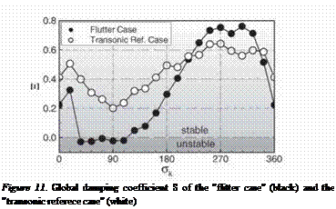
In order to assess how these contributions affect the flitter behavior of the cascade, a global damping parameter was evaluated as follows: With the def­inition of the unsteady pressure coefficient according to eq. (6), the unsteady moment coefficient Cm is calculated. Using the imaginary part, the global damping coefficient is defined as

Подпись:
A positive value of S represents stability with damped oscillations; negative values indicate instability.

It can be seen, that in both cases the traveling wave modes with the lowest aerodynamic damping occur at IBPA near 90° . Especially for the flitter case, the aerodynamic damping for IBPA between 36° and 108° is negative, i. e. if the structural damping could not compensate this aerodynamic instability, the cascade starts to flutter.

Investigated Flow Cases

The aim of the experiments was to investigate the behavior of a cascade running into flitter. In order to decrease the reduced frequency

* о / cred / A ч

U) — Z7T —- (4)

Vi

with respect to the same infbw velocity v i the cascade was tuned to a lower torsional blade eigenfrequency. So it was possible to investigate an unstable aeroelastic condition at a transonic fbw case, which had been previously in­vestigated.

Table 1. Steady upstream and downstream fbw parameters

Transonic Reference Case

Flutter Case

u*

0.362

0.289

Upstream:

Downstream:

Upstream:

Downstream:

Ma

0.87

0.72

0.90

0.75

P

50.3 °

41.5 °

50.4°

40.1 °

Pt

1323 mbar

1254 mbar

1397 mbar

1311 mbar

V

814 mbar

854 mbar

836 mbar

834 mbar

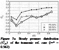
The transonic fbw condition is characterized by the occurrence of a front shock at x/c & 0.25…0.35 and a channel shock at x/c & 0.65…0.85 on the suction side and at x/c & 0.25…0.35 on the pressure side (Fig. 7b). In – and out-fbw parameters are mentioned in Table 1. Releasing the hydraulic brake at this fbw condition, it was possible to set the blade assembly to controlled pitching oscillations around midchord for each interblade phase angle and to measure the unsteady pressure distribution up to a pitching amplitude of ap­proximate 0.1° in order to determine the aerodynamic damping following the "aerodynamic approach". The excitation frequency of 177 Hz was choosen slighly below the eigenfrequency of the blades in order to distuinguish forced and free vibrations in the frequency range. This excitation frequency corre­sponds to a reduced frequency cj* = 0.289. Exceeding this amplitude the cascade starts to vibrate with a frequency of 182 Hz (“Flutter Case” Table 1).

Подпись: Figure 7a. Steady pressure distribution (Cp) of the transonic ref. case (>•* = 0.362)
Investigated Flow Cases

With the same cascade, an aerodynamic damping investigations was per­formed following the "aerodynamic approach" with each blade tuned to a higher eigenfrequency and excited at 215 Hz (cc* = 0.362). Here the cas­cade remained aerodynamically and aeroelastically stable (‘Transonic Refer­ence Case” Table 1).

Figure 7b. Steady pressure distribution (Cp) of the Hitler case (w * — 0.289)

Experimental Investigations

As blade flitter in axial turbomachines is caused by an interaction of the blade motions and the motion-induced unsteady aerodynamic forces, the main parameters for flitter beside the cascade’s geometry and structural properties are the fl»w conditions and the damping properties of the structure. Hence, two different approaches for experimental flitter investigations are possible: in the so-called "aerodynamic approach” a certain level of structural damp­ing is needed for the blades to prevent self-excited vibrations if the cascade

is aerodynamically unstable. In order to determine the aerodynamic damp­ing the blades are forced into controlled harmonic vibrations in each traveling wave mode successively and the motion induced unsteady pressure distribu­tions is measured. The analysis of this data — in particular the out-of-phase unsteady harmonic pressure — leads to an estimation of the aerodynamic sta­bility of each traveling wave mode. In a so-called "aeroclastic approach" the aerodynamic instability can overcome for the structural damping and the cas­cade starts to Hitter. With the use of some safety devices (like hydaulic flitter brakes), the blade vibrations and the unsteady pressure distributions can be measured at the onset of flitter.

In order to drive the cascade into flitter each blade was tuned to a lower cigcnfrcqucncy of 183 Hz by increasing the mass moment of inertia. This cas­cade was mounted in the annular wind tunnel. Steady fbw conditions were achieved by adjusting the inlet total pressure, the inlet infbw angle, and the back pressure. A hydraulic brake prevented blade vibrations during the ad­justment of the steady ftm These fbw conditions were surveyed by probe measurements of upstream and downstream fbw field and by measuring the steady pressure distribution on the blades.

At the up – and down-stream fbw field an aerodynamic probe was used to scan one pitch of the cascade by taking small steps in the radial and circum­ferential directions. The measured probe pressures w’ere used to compute mass fbw averaged in – and out-fbw values such as p tl, pt2, pi, p->, etc. (Table 1). The steady pressure distribution the blades were measured with pressure taps on the pressure and suction surface at nine equidistant chordwise positions and the three radial positions z/h = 0.2, 0.5, and 0.8 on several blades. They were transformed to steady pressure coefficients

Подпись:P ~ ‘P i Pti ~ Pi

Подпись: й 0J5 0.5 0.75 1 0 025 0.S 0.7S I Figures. Location of ihe pressure laps Figure 6. Location of the piezoelectric pressure transducers

using the mass fbw averaged values of the infbw total and steady pressure p ц and pi, respectively (Fig. 5).

Afterwards, the hydaulic brake w’as released to set the blade assembly to controlled pitching oscillations for the performance of the unsteady measure­ments ("aerodynamic approach") or to allow self-excited vibrations for the performance of the flitter experiments ("aeroelastic approach"). The unsteady pressure distribution was measured by 25 piezoelectric transducers, 15 of w’hich
are mounted on the suction side and 10 on the pressure side of the blades. The transducers were distributed in blocks on only four blades. In each block, the transducers are located close together in order to resolve the unsteady pressure distribution near possible shock positions (Fig. 6).

The blade vibrations were measured by an eddy-current displacement sensor for each blade.

Annular Test Facility Annular Wind Tunnel

The experimental investigations presented here were performed in the wind tunnel for annular cascades at the EPFL. The annular cascade tunnel was de­veloped for a research project between BBC and the EPFL to investigated the steady and unsteady ft>w in annular cascades without having to rotate them; Bolcs (1983). A spiral ft>w is generated in order to simulate real inflow an­gles such as those that would occur in a rotating cascade. Figure 1 shows the cross-section of the wind tunnel. The advantage of an annular cascade such as circumferential ft>w periodicity is combined with the advantage of a fixed cas­cade in respect of data aquisition and data transfer. Steady ft>w conditions are measured by aerodynamic probes in the upstream and downstream sections and by pressure taps on the blades’ surfaces. The aerodynamic probes were calibrated to obtain the total pressure ptl and pt2, the steady pressures p1 and p2, the ft>w angles в і and вг, and the Mach numbers Ma 1 and Ma2 from the measured pressure data.

1.1 Cascade

The compressor cascade used here is composed of 20 blades with a NACA 3506 profile of c = 80 mm in nominal chord length, a stagger angle of вд = 40° , and a pitch at midspan of s = 56.5 mm (Fig. 2). The profiles were shortened to a cred = 77.5 mm chord length with a round trailing edge (see

Annular Test Facility Annular Wind Tunnel

Figure 2. Components and geometry of the cascade


also Fig. 5 and 6). The blades are mounted via elastic spring suspensions which allow a torsional motion around midchord.

A NACA3506 profile was chosen for the investigations of tuned bending vibrations by Kbrbacher (1996). The fact that pitching motions of this pro­file should be more critical in aeroelastic stability – mainly for transonic fbw conditions – was the reason why investigations of the aerodynamic damp­ing using excited pitching vibrations were carried out by Hennings and Beiz (1999, 2000). For the fijtter measurements the blades are tuned to lower eigen – frequencies in order to reach an aerodynamically as well as aeroelastically un­stable case. For the latter one the aerodynamic self-excitation has to surpass the structural damping of the cascade, namely of the elastic spring suspension.

For experimental investigations concerning the aerodynamic damping, the blades are driven by electromagnetic exciters such that their motions represent a traveling wave modes with one of the possible interblade phase angles

Annular Test Facility Annular Wind Tunnel(1)

given by the number of N = 20 blades. The unsteady pitching motions

Подпись: (2)ati(t) = a ■ cos(Ш — і og)

of the blades are controlled in both their amplitudes a and interblade phase angles (Tk■ Tn order to reach appropriate amplitudes, the inertia of each blade and the vibrating part of the inner wall of the wind tunnel had to be reduced and the blades had to be excited near resonance (Figure 3 shows the assembly of the cascade). Lowering the eigenfrequencies by a minor mass moment of inertia, the torsional stiffness had to be reduced as well. So, the demand of both lower torsional stiffness (in presence of a high transversal stiffness to avoid a heaving motion) and lower structural damping led to a new one-piece spring suspension.

The spring suspension was made out a cylindrical part by cutting sections out using electrical discharge machining. The remaining section consists of

Annular Test Facility Annular Wind Tunnel

Figure 3. Annular cascade with some blades removed

Annular Test Facility Annular Wind Tunnel

Figure 4. Elastic spring suspension

eight rectangular beams orientated such that the torsional stiffness is low and the transverse stiffness is high. The use of electrical discharge machining made it possible to manufacture the spring suspension out of one part, which results in a very low structural damping (see Figure 4).

EXPERIMENTAL FLUTTER INVESTIGATIONS OF AN ANNULAR COMPRESSOR CASCADE: INFLUENCE OF REDUCED FREQUENCY ON STABILITY

Joachim Belz and Holger Hennings

DLR – Institute ofAeroelasticity

Bunsenstrasse 10

D-37073 Gottingen, Germany

joachim. belz@dlr. de

holger. hennings@dlr. de

Abstract Due to the trend of increasing power and reducing weight, the fan and compres­sor bladings of turbomachinery might be more sensitive to flitter, which must strictly be avoided already in the design process. In order to increase our under­standing of the flitter phenomena for fan and compressor cascades, aeroelastic investigations are essential.

This paper presents the achievements and results of experimental flitter in­vestigations with a compressor cascade in the test facility of non-rotating annular cascades at EPFL. Flow conditions such as those that occur in rotating cascades are simulated by generating a spiral fbw in the upstream. The construction of the cascade which takes into account the structural properties necessary to per­form flutter experiments is described. For the simulation of elastic torsional vibrations of a two-dimensional blade section, the cascade consists of 20 blades (NACA3506 profile) mounted on elastic spring suspensions which allows for torsional motion about the midchord.

In order to investigate the inflience of the reduced frequency on the global stability of the cascade and its local contibutions, experiments were performed for two different reduced frequencies. At the higher reduced frequency the cas­cade remains aerodynamically stable, however, at the lower reduced frequency and transonic flow conditions, some of the interblade phase angles appear to be aerodynamically unstable.

Keywords: Flutter, Reduced Frequency, Experiments, Annular Cascade

77

K. C. Hall et al. (eds.),

Unsteady Aerodynamics, Aeroacoustics and Aeroelasticity of Turbomachines, 77-91. © 2006 Springer. Printed in the Netherlands.

Introduction

The demand for a decrease in engine weight and a reduction in fuel con­sumption has, among other things, led to engines that contain a decreased num­ber of compressor stages and slender fan or compressor blades. This results in both more fhxible blades and in higher pressure ratios at each stage with a higher fbw velocity around the blades. The variations of these parameters in – flience the aeroelastic stability of the blade assembly and can lead to flitter, i. e. self-excited blade vibrations due to an interaction with the motion-induced unsteady aerodynamic forces. For this reason, aeroelastic investigations are es­sential to provide detailed knowledge about flitter phenomena, especially for compressor cascades in transonic fl»w. Experimental data of unsteady aerody­namic and flitter tests are required for the validation of theoretical results as well.

In the past years, the increasing number of theoretical investigations has been accompanied by several experiments on vibrating cascades. Szechenyi et al. (1980), Carta (1982), Buffum et al. (1998), and Lepicovski et al. (2002) have obtained unsteady aerodynamic data by harmonic torsional oscillations of one blade or all blades of their linear compressor cascades. Carta partic­ularly showed the influence of the interblade phase angle on stability at low Mach numbers, whereas Szechenyi and Buffum concentrated their investiga­tions on the infhence of large incidence angles on stability. Korbacher (1996) investigated the bending motion of the blades of a compressor cascade in an annular wind tunnel. A cascade with the same geometry was used by Hennings and Belz (1999, 2000) to examine the aerodynamic damping by forced pitch­ing motions of the blades with respect to shock movements. The results were compared with theoretical investigations by Carstens and Schmitt (1999) as well as Kahl and Hennings (2000), who took into account leakage fl>w effects.

The experimental investigations presented here were performed in the wind tunnel for annular cascades at the Ecole Polytechnique Federale de Lausanne (EPFL). This wind tunnel has been used by several other researchers for the measuring of unsteady pressure distributions due to blade vibrations for aero­dynamic stability investigations of compressor and turbine cascades or up­stream generated aerodynamics gusts for forced response investigations. The following investigations performed are cited as examples: Korbacher and Bolcs (1996), Korbacher (1996), Nowinski and Panovsky (1998)), Rottmeier (2003).

The aim of the investigation presented here was to investigate the influence of reduced frequencies on the cascade’s aerodynamic and aeroelastic behavior at transonic flow. Two reduced frequencies were chosen in such a manner, that in one case self-excited cascade vibration (flutter) occured and in the other case the cascade remained aerodynamically stable. In order to realize cascade flutter the structural damping had to be minimized by redesigning the elastic

EXPERIMENTAL FLUTTER INVESTIGATIONS OF AN ANNULAR COMPRESSOR CASCADE: INFLUENCE OF REDUCED FREQUENCY ON STABILITY

spring suspensions. The unsteady pressure distribution, the infhence of the shock impulse at transonic fOw conditions, and the local and global stability measured for the two reduced frequencies are compared.

Suppression of unstable vibration by the trailing edge oscillation

To confirm the effectiveness of the control method with trailing edge oscil­lation, the case of 5 = 45 degrees was analyzed by the fbw-stmcture coupled method. The initial velocity of V0=0.01Cw was given to No.1 blade, and that of -Vo was given to No.3 blade. No.2 and No.4 blades had the initial displace­ment (No.2 blade; h0=0.01C, and No.4 blade; – h0) to simulate the case when

all blades oscillate with 90 degrees of inter blade phase angles at the initial state of computation. The trailing edges of No. I and No.3 blades were actively oscillated. Since the blade oscillation frequency is an implicit parameter in the fbw-structure coupled method, the blade oscillation frequency is calculated in the present study by the Fourier transfer of blade displacement to obtain w the angular frequency. The blade displacement /?/ and ф arc calculated from the following equations;

h! = sin (cot + 0) where., в = arctan j

(2)

v МЦ )

ф — В sin (cot + 9 + S)

(3)

Figure 16 show’s the time history of the blade displacement and the unsteady aerodynamic force when 5 is about 45 degrees. The result of the case without control is also indicated by the dotted line for comparison. As shown in Fig. 16, the increase in the displacement of all blades is effectively suppressed by the trailing edge oscillation. In the controlled case, the phase of the unsteady aero­dynamic force delays compared with that of the blade displacement.

From the analysis by fbw structure coupled method, it can be concluded that the method of active trailing edge oscillation can effectively suppress the cascade fhtter in transonic fbw’ regime.

2. Conclusions

Possibility of active cascade fitter control under transonic fbw condition with passage shock waves was numerically studied. Two methods of flitter

Suppression of unstable vibration by the trailing edge oscillation

Figure 16. Time Histor’ of the Blade Displacement and the Unsteady Aerodynamic Force (with Trailing Edge Oscillation)

control were analyzed by the developed numerical code. In the first method, the direction of the oscillatory motion of blades was actively changed. The method can be realized with some kind of shape memory alloy. The second control method gives active oscillation to the blade trailing edge with a fhp – like manner. The active vibration can be realized with piezo-electric devices.

The conclusions are summarized as follows.

1 In the adopted cascade model, the unsteady aerodynamic force induced by passage shock movement was dominant for instability of blade vibra­tion.

2 The control method with changing oscillation direction can control the passage shock movement near the blade surface, and change the un­steady aerodynamic force induced by the passage shock from exciting to damping one.

3 By the method of active trailing edge vibration, the unsteady aerody­namic force induced by the passage shock oscillation can be changed from exciting to damping force if the phase of the trailing edge vibration is properly selected compared with that of blade oscillation. The cascade flitter can be effectively suppressed in the case. At an improper phase, on the contrary, the control increases the exciting force on the blade.

References

A. H. Epstein, J. E. Ffowcs Williams, and E. M. Greitzer, "Active Suppression of Aero­dynamic Instabilities in Turbomachines", Journal of Propulsion and Power, Vol. 5, No.2, 1989, pp. 204-211.

Nagai, K. and Namba, M., "Effect of Acoustic Control on the Flutter Boundaries of Super­sonic Cascade", Unsteady Aerodynamics and Aeroelasticity of Turbomachines, Fransson, T. H. ed., Kluwer Academic Publishers, 1998, pp.165-179.

Xiaofeng Sun, Xiaodong Jing, and Hongwu Zhao, "Control of Blade Flutter by Smart­Casing Treatment", J. of Propulsion and Power, Vol.17, No.2, 2001, pp248-255.

For Example, L. B. Scherer, C. A. Martin, M. West, J. P. Florance, C. D. Wiesman, A. W. Burner, and G. A. Fleming, "DARPA/AFRL/ NASA Smart Wing Second Tunnel Test Results", SPIE Vol.3674, pp.249-259.

Kazawa, J. and Watanabe, T. , "Numerical Analysis toward Active Control of Cascade Flutter with Smart Structure", 38th AIAA/ASME/SAE/ASEE Joint Propulsion Conference and Exhibit, 7-10 July 2002, Indianapolis, Indiana. AIAA Paper 2002-4079.

"Experimental Quiet Engine Program," contract No. NAS3-12430, March 1970.

Shibata, T. and Kaji, S. , "Role of Shock Structures in Transonic Fan Roter Flutter", Proc of the 8th International Symposium: Unsteady Aerodynamics of Turbomachines and Pro­pellers, Fransson, T. H. ed, Sept. 1997, pp.733-747.

Hanamura, Y., Tanaka, H., and Yamaguchi, K., "A Simplified Method to Measure Un­steady Forces Acting on the Vibrating Blades in Cascade", Bulletin of JSME, 1980, Vol.23, No.180, pp.880-887.

Analysis in the case when all blades are forced to oscillate

The phase difference between blade vibration and trailing edge oscillation, denoted as 5, was found to be important in the present analysis. 5 is positive when the phase of trailing edge oscillation advances compared with that of the blade vibration. Eight cases of 5, 5 = -135, -90, -45, 0, 45, 90, 135, 180 (deg.), were analyzed in the study, and two characteristic results of 5 = 45 and 5 = -135 (deg.) cases are reported here.

For the feasibility study of the method, the case in which all blades were forced to oscillate with 90 degrees of inter blade phase angle were analyzed first. The trailing edges of No.1 and No.3 blades were oscillated and those of No.2 and No.4 blades were not oscillated.

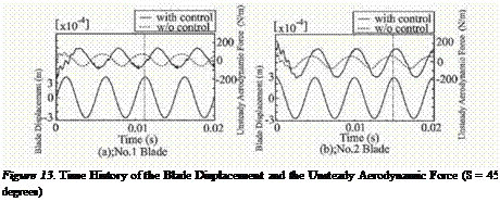
Figure 13 shows the time history of the displacement and the unsteady aero­dynamic force of the No.1 and No.2 blades when 5 = 45 (deg.). In Fig.13, dot-

Analysis in the case when all blades are forced to oscillate

Подпись:
Analysis in the case when all blades are forced to oscillateted line indicates the results of the case without control (trailing edges of the blades are not oscillated). In the controlled case, the blade with trailing edge oscillation (in this case, No.1 and No.3 blades) is called "controlled blade”, while the blade without trailing edge oscillation (No.2 and No.4 blades) is called "non-controlled blade." In the results of the case without control (dotted line) shown in Fig.13, the phase of the unsteady aerodynamic force advanced compared with that of the blade displacement. In this situation, the unsteady aerodynamic force acts on blade as an exciting force, so that the blade vibra­tion is unstable. On the other hand, in the case with trailing edge oscillation (5 = 45 deg.), the phase of the unsteady aerodynamic force delays compared with that of blade displacement on both controlled and non-controlled blades. In this situation, the unsteady aerodynamic force acts on the blade as a damping force. From the result, it is found that the trailing edge oscillation can change the unsteady aerodynamic force from exciting to damping force when 5 is 45 degrees.

Подпись: Bad Analysis in the case when all blades are forced to oscillate Analysis in the case when all blades are forced to oscillate Analysis in the case when all blades are forced to oscillate Analysis in the case when all blades are forced to oscillate

Подпись:

Подпись: Distance alog Chord, c'C

Подпись: region

Подпись: (a);No.l Blade Подпись: flapping oscillation Подпись: (b);No.2 Blade

Figure 14 shows the unsteady aerodynamic work distribution on No.1 and No.2 blades when 5 = 45 deg. The peak around 50% chord position on the

Analysis in the case when all blades are forced to oscillate

Figure 15. Unsteady Aerodynamic Work Distribution on Blade Surface (S = -135 degrees)

pressure surface of controlled blade is seen to become low by trailing edge oscillation. Since the passage shock movement induces this peak, it can be said that the trailing edge oscillation alters the passage shock oscillation. The unsteady aerodynamic work around the fhpping oscillation region is different from that of the case without trailing edge oscillation, which is also caused by the trailing edge oscillation. Through the integration of the chordwise distri­bution of unsteady aerodynamic work shown in Fig. 14(a), the total value of unsteady aerodynamic work was found to shift from positive one to negative one. From Fig. 14(b), the results of non-controlled blade, the positive peak around 50% chord in the pressure surface changes to negative one.

Figure 15 shows the unsteady aerodynamic work distribution on No.1 and No.2 blades when 5 = -135 degrees. The peak level around 50% chord in the pressure surface of controlled blade was same as that in the case without control. On the other hand, the unsteady aerodynamic work on the fhpping os­cillation region was increased by this control. In the results of non-controlled blade as shown in Fig. 15(b), the unsteady aerodynamic work induced by pas­sage shock movement is observed to increase in the case with control. When 5 = -135 degrees, therefore, the trailing edge oscillation increases the exciting force on the blades compared with that in the case without control.

In the present control method with trailing edge oscillation, the phase dif­ference 5 is a quite infhential factor for instability. The proper selection of 5 is very important.