Category UNSTEADY AERODYNAMICS, AEROACOUSTICS AND AEROELASTICITY OF TURBOMACHINES

Analysis of Flutter suppression by Trailing Edge Oscillaton

From the results of detailed analysis, the control method by changing os­cillation direction was found not effective when the blade stiffness was small. As a more general control method effective for transonic cascades, the active vibration of blade trailing edge was found to have great potential. Figure 10 illustrates the method of the trailing edge oscillation. The region of flapping oscillation extends about 30% chord length from the trailing edge. The angu­lar displacement of the oscillation is ф. The active vibration of trailing edge oscillation can be realized by, for instance, piezo-electric device. The active trailing edge oscillation is expected to provide desirable change in the oscilla­tory motion of passage shock wave as shown in the previous case.

Analysis of Flutter suppression by Trailing Edge Oscillaton

Figure 10. Oscillation of Blade Trailing Figure 11. Flat Plate equipped with

Edge Piezo-Electric Device

As a test case, a piezo-electric device was mounted on a fkt plate as shown in Fig.11, and the active vibration of the plate was observed. Figure 12 shows the sketch of the trailing edge oscillation. The displacement of the trailing edge was measured from the photograph, and a displacement of the trailing edge by around 0.2mm was found.

Flutter Suppression by Changing Direction of Blade Oscillation

The control by changing the oscillation direction of blade was numerically analyzed. The control method is thought possible by application of a kind of shape memory alloy.

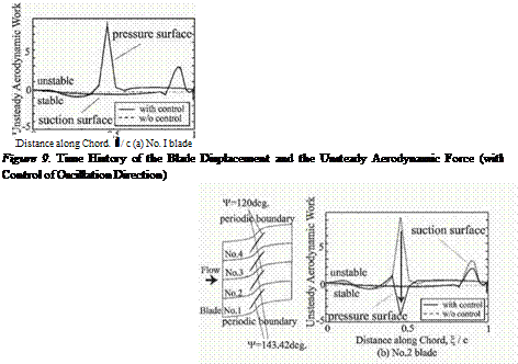
To study the effectiveness of the control, the case in which all blades were forced to oscillate were analyzed in 4 fbw channels with 90 degrees of inter blade phase angle as shown in Fig. 8. The oscillation directions of No.1 and No.3 blades were set to be 143.42 degrees, while those of No.2 and No.4 blades were 120 degrees. Figure 8 shows the chordwise unsteady aerodynamic work distribution on the blade surface. Solid line is the result of the case with control, while dotted line is that of the case without control. Figure 8(a) is the result of No.1 blade (Ф =143.42 deg.), and Fig. 8(b) is that of No.2 blade (Ф =120 deg.). From Fig. 8(a), it is seen that the result of the controlled case is almost the same as that of the case without control for No. 1 blade. For the No. 2 blade, however, the peak at 50% chord position on the pressure surface changes from positive one to negative one by the control as shown in Fig. 8(b). Alteration of the blade oscillation direction should change the movement of passage shock, and the induced unsteady aerodynamic work should thereby be changed into, possibly, stable direction.

Based on the previous results, the control method of changing oscillation direction of blade was analyzed by the fbw-structure coupled method. Initial velocity of 0.01Cw (C:chord length, w:angular frequency of blade) was given to No.1 blade, and -0.01Cw to No.3 blade. No.2 and No.4 blade were set

Flutter Suppression by Changing Direction of Blade Oscillation

Figure 8. Variation of Unsteady Aerodynamic Work Distribution on the Blade Surface due to the Direction of Oscillation

Flutter Suppression by Changing Direction of Blade Oscillation
stationary at the initial state. The angle of blade motion, Ф, of all blades was initially 120 degrees. The angle Ф of No.1 and No.3 blades was impulsively changed to 143.42 degrees from 120 degrees at the time when the displacement of the blades started to increase.

Figure 9 shows the time history of the displacements of No.1 and No.2 blades as well as the unsteady aerodynamic force on these blades. The dot­ted line indicates the result when Ф of all blades are kept 120 degrees for comparison. As shown in Fig.9, the increase in displacement was effectively suppressed by changing oscillation direction. The phase of the unsteady aero­dynamic force is observed to delay compared with that of the blade displace­ment after the start of the control. In this situation, the unsteady aerodynamic force acts as a damping force on the blade. As for the No.2 blade, the result corresponds to that of the previous result shown in Fig. 8. The displacement of No. 1 blade was decreased probably because of the inflience of the decrease in the displacement of No.2 blade.

An Analysis of Blade Vibration Instability

The tip section of Quiet Fan B in NASA Quiet Engine Program [6], shown in Fig.4, was adopted as the cascade model for the present analysis. Figure 5 shows the computed steady Mach contours in the case when inlet Mach number is 1.25, and the static pressure ratio (po/pi, i;inlet, o;outlet) is 1.7. A passage shock wave generated at the trailing edge of each blade can be clearly seen in flow channels. Concerning vibration instability of this cascade model, the oscillation of the passage shock wave is known to be the most influential factor. An oblique shock is generated at the leading edge of each blade, and impinges to the suction surface of the adjacent blade.

An Analysis of Blade Vibration Instability

— pressure surface

– – – suction surface


An Analysis of Blade Vibration Instability

stable


Distance along Chord, £/C
(a);4/=143.42(deg)


An Analysis of Blade Vibration Instability

An Analysis of Blade Vibration Instability

Figure 7. Unsteady Aerodynamic Work Distribution on the Blade Surface

The blade vibration instability was investigated in the above ft>w field. The blade was forced to oscillate with the reduced frequency of 0.084. The direc­tion of blade motion, Ф, was 143.42 degrees (case 1) and 120 degrees (case 2). Since a realistic blade is designed in a three-dimensional manner, the stagger angle is different in the spanwise direction. The difference of stagger angle re­sults in the change in the direction of blade oscillation at each spanwise section of the blade. It is reported that the oscillation direction plays an important role for the blade vibration instability in the transonic ft>w condition [7].

The inflience coefficient method [8] was used for analysis of blade vibration instability. Figure 6 shows the result of instability analysis by this method when the reduced frequency is 0.084. The horizontal axis is the inter blade phase angle, while the vertical axis corresponds to the unsteady aerodynamic work on a blade. Blade vibration is unstable when the aerodynamic work is positive. As shown in Fig.6, blade vibration was always stable in the case 1. In the results of the case 2, on the other hand, the blade oscillation was unstable around 90 degrees of inter blade phase angle.

Figure 7 shows the chordwise unsteady aerodynamic work distribution on the blade surface when all blades were forced to oscillate with 90 degrees of inter blade phase angle. Figure 7(a) shows the results of the case 1, while Fig. 7(b) shows those of the case 2. At the part where the unsteady aerodynamic work is positive, the unsteady aerodynamic force acts as exciting force. In the results of Fig. 7(a), a negative peak can be seen at around 50% chord position on the pressure surface. The peak is caused by the oscillation of passage shock. In the result of the case 2, Fig. 7(b), the peak is observed to be positive, which means that the unsteady aerodynamic work induced by passage shock move­ment becomes exciting one. The characteristics of unsteady aerodynamic force thus differ depending on the blade oscillation direction. The unsteady aerody­namic work due to the shock oscillation is revealed to be dominant for blade vibration instability in the result, because the value of the peak is larger than that at another position on the blade surface. On the suction surface, on the

other hand, a positive peak is observed at around 90% chord position both in the case 1 and case 2. The peak is caused by the oscillation of the oblique shock impinges there from the leading edge of the neighboring blade.

Numerical Argorithm

A numerical fl>w-structure coupled method has been developed in the course of the present study [5]. Figure 1 shows the procedure of the method. The com­puted unsteady aerodynamic force in the flow calculation is introduced into the structural calculation in which the equation of motion of the blade is solved to obtain the blade displacement. The computed blade displacement is used for generation of the new grid coordinates in the next time step of fl>w calculation.

The fl>w calculation is based on the two-dimensional nonlinear Euler equa­tion, that is solved through a second order upwind TVD scheme. LU-ADI

Numerical Argorithm

Slip Boundary Condition

Figure 2. Computational Domain, Grid, Boundary Conditions


Figure I. Procedure ol‘ Flow Structure Coupled Method


Numerical Argorithm

factorization algorithm coupled with Newtonian iterations is used as the time – marching scheme. Figure 2 shows computational domain, grid, and boundary conditions. The number of fbw channel, N, can be arbitrarily selected in the computation, and the inter blade phase angles of 360n/N (n=’l,2, …, N) can exist in N fbw channels. Periodic boundary conditions were imposed on the upper and lower side of the computational domain, that is, physical values at the lower boundary of No. 1 fbw region and those at upper boundary of No. N fbw region were set to be same. At the inlet boundary, total pressure, total tem­perature, and rotational speed (tangential velocity) were fixed. Non-refbcting boundary condition was used on the inlet boundary to prevent refection of the wave induced by the blade vibration. Static pressure was specified at the outlet boundary, and the blade surfaces were treated as slip boundaries. H+O+H grid was adopted for computation. О grid was used around the blades to achieve good orthogonality, and H-grids were generated in upstream and downstream regions in order to make inlet and outlet boundaries distant from the blades.

Figure 3 shows structural model of blades in one-degree of freedom. The direction of blade movement, indicated by the angle Ф in Fig.3, can be arbi­trarily selected. The equation of motion of structural model as shown in Fig.3 is written by the following equation (I);

Numerical Argorithm(I)

where M is blade mass, h is blade displacement, D is structural damping, К is blade stiffness, and L is unsteady aerodynamic force acted on blade. This equation was solved through Runge-Kutta-Gill scheme. The structural

Numerical Argorithm

Figure 3. Structural Model

Figure 4. Cascade Model (Tip Section of Quiet Fan B)

damping, D, was neglected in the present analysis to concentrate our focus on the aerodynamic damping effect in the fbw-structure coupled situation.

POSSIBILITY OF ACTIVE CASCADE FLUTTER CONTROL WITH SMART STRUCTURE IN TRANSONIC FLOW CONDITION

Junichi Kazawa Toshinori Watanabe

Department of Aeronautics and Astronautics, University of Tokyo 7-3-1 Hongo Bunkyo-ku, Tokyo 113-8656, Japan Phone : +81 3 5841-6624 Fax : +81 3 5841-6622 kazawa@aero. t.u-tokyo. ac. jp

Abstract To study the possibility of active cascade flitter control by application of smart structure, numerical analyses were performed under transonic flaw conditions with passage shock waves by a developed flaw-structure coupled method. In the flow condition of the present study, the unsteady aerodynamic force induced by the shock oscillation was dominant for instability of blade vibration. The direction of blade movement during oscillation was first adopted as the control parameter, because it was known to be a quite influential factor for vibration in­stability of blades in the transonic flows. The method could decrease the passage shock movement near the blade surface and effectively suppress the blade vibra­tion, though it was not effective when the blade stiffness was small. For more effective control, the method in which the trailing edge of blade was actively vibrated was sought to control the passage shock oscillation. The trailing edge oscillation might be realized by, for instance, application of piezo-electric de­vice. The method was revealed to change the unsteady aerodynamic force acted on the blade from exciting to damping force if the phase of trailing edge oscil­lation was properly selected. The suppressing effect of the control method came from its effect on passage shock movement, which was confirmed by developed flow-structure coupled method.

1. Introduction

Active control of surge and rotating stall has been successfully studied in the last decade [1] including phenomenological description of the onset of insta­bility and control mechanism. Concerning the cascade flitter problem, some active control techniques have also been reported, in which acoustic waves are introduced to suppress the flitter [2], or the acoustic impedance on casing wall is actively controlled to reduce the exciting energy of the oscillating blade [3].

65

K. C. Hall et al. (eds.),

Unsteady Aerodynamics, Aeroacoustics and Aeroelasticity of Turbomachines, 65-76. © 2006 Springer. Printed in the Netherlands.

On the other hand, the study of "smart structure" has been advanced in the research field of structures and materials. The smart materials can deform themselves reacting to electric signals. Active control techniques, in which the smart materials are applied to the fhp of the aircraft wing or fuselage panel, have been proposed so far [4] to prevent flitter instability of them. If the char­acteristics of smart materials are properly utilized for the active control of cas­cade flitter, an effective and reliable control method can be realized since such materials directly change the structural characteristics of the vibrating materi­als, or can give fexible deformation of the blades.

The authors have studied some methods of cascade flutter control by use of the developed fl>w-structure coupled method. For example, flitter suppres­sion was found to be possible by changing natural frequency of blade in the subsonic fliw condition [5]. The control can be realized by the application of Shape Memory Alloy.

In the present study, two methods of the cascade flutter control were ana­lyzed for suppression of vibration instability in transonic flow conditions with passage shock waves. In the studied fl>w condition, it is well known that the unsteady aerodynamic force induced by the movement of passage shock wave is dominant for blade vibration instability. It is also known that the direction of blade movement during oscillation is a quite influential factor for flutter instability.

Based on the knowledge above, the possibility of flitter suppression by changing the oscillation direction of blades was investigated first. The change in the direction can be carried out with, for instance, some kind of shape mem­ory alloy. The second method was to give forced oscillation on the trailing edge section of blades. It was thought that the occurrence of cascade flitter could be suppressed through the change in the oscillatory motion of shock waves im­pinged to the blade surfaces. The forced vibration of the trailing edge section can be realized with piezo-electric devices.

The results of these numerical studies are reported in the present paper.

Numerical and Experimantal Results

The aeroelastic behavior of the system "fbw-cascade" without taking into account the mechanical damping is defined by a the work coefficient value which is equal to the work performed by aerodynamic forces during one cycle of oscillations:

і

V

W = J M^dt, (5)

0

where c is the length of blade chord, ao is oscillation amplitude, M is aerody­namical moment, W is the aerodynamic work during one cycle of oscillation for torsional oscillations, and

і

V

W = J-F-vdt, (6)

0

for bending oscillations.

The work coefficients versus interblade phase angle (IBPA) for different fbw regimes and modes of oscillations are presented in Figures 5-7.

Figure 5 shows the work coefficient as function of IBPA for bending oscil­lations under incidence fbw angle which is equal to zero. The light squares (circles) correspond to the experimental data, the black squares (circles) cor­respond to numerical results. The negative values of work coefficient demon­strate the dissipation of an oscillating blade energy to the fbw (aerodamping), the positive values – to the transfer of the energy from the main fbw to the blade (flitter).

The strong infbence of both IBPA and Strouhal number on the aerodynamic stability of tune modes is seen in Figure 5. With decreasing of Strouhal number (increasing of the inlet fbw velocity) the stability decreases.

It should be noted that the work coefficient in dependence of IBPA has a typ­ical sinusoidal form. At the IBPA equal to 180 deg the maximal aerodamping is observed, at the IBPA near 0 deg the minimal aerodamping is found.

The quantitative and qualitative agreement between predicted and measured values is satisfactory.

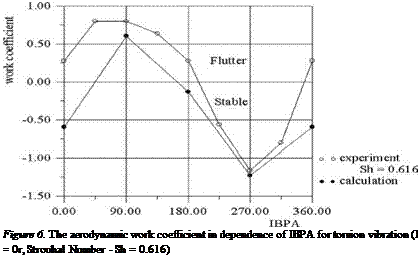
In Figure 6 the variation of work coefficient versus IBPA for torsional oscil­lations under і = 0 and Sh = 0.616 is shown. The agreement between theoretical

Figure 5. The aerodynamic work coefficient in dependence of IBPA for the bending vibration (i = 0r, Strouhal Number – Sh = 0.2 – 0.616)

Подпись: Figure 6. The aerodynamic work coefficient in dependence of IBPA for torsion vibration (I = 0r, Strouhal Number - Sh = 0.616)

and experimental results is good. For torsional oscillations in the range of 0 deg. < IBPA < 180 deg. the work coefficients have positive value that cor­responds to the transfer of energy from the flow to the oscillating blade. The maximal excitation occurs near 5 = +90 deg.

The aeroelastic characteristics at the bending vibration for the attack flow angle of 16 deg is presented in Figure 7. The agreement between the exper-

Numerical and Experimantal Results

Figure 7. Aerodynamic work coefficient in dependence of IBPA for the bending vibration (i = 16r, Strouhal Number – Sh = 0.616)

imental and numerical results near the IBPA of 0 deg is seen although some discrepancy for IBPA of 180 deg is found.

In Figures 8, 9 and 10 the calculated and measured amplitude of unsteady forces at the bending oscillations, for different incidence angles were shown. The calculation of the unsteady amplitude by using the aerodynamic inflience coefficients were done taking into account only four neighbouring blades (-1 < n < 1) and two neighbouring blades (-2 < n < 2). From results presented in these Figures it is seen that for considered flow regime taking into account only two neighbouring blades give the satisfactory agreement with numerical calculations.

3. Conclusions

1. A partially – integrated method based on the solution of the coupled aerodynamic-structure problem is used for calculation of unsteady 3D fbw through an oscillating blade row to determine the critical conditions of flutter initiation.

2. The numerical investigation has been performed to calculate aeroelastic response of the compressor cascade at the different flow regimes and laws of oscillations.

3. The comparison of calculated and experimental results for bending and torsional oscillations has shown a satisfactory quantitative and qualitative agree­ment.

Numerical and Experimantal Results

Figure 8. Amplitude of unsteady aerodynamic force at the bending oscillations

Numerical and Experimantal Results

Figure 9. Amplitude of unsteady aerodynamic force at the bending oscillations i = 0, Sh = 0.616

References

Bolcs A., Fransson T. H. (1986) Aeroelasticity in Turbomachines Comparison of Theoretical and Experimental Cascade Results, Communication du Laboratoire de Thermique Appliquee et Turbomachines, Nr.13. Lusanne, Epfel.

Bolcs A., and Fransson T. H. (1986). Aeroelasticity in Turbomachines Comparison of Theoret­ical and Experimental Cascade Results, Communication du Laboratoire de Thermique Ap­pliquee et Turbomachines, Nr.13, Appendix A5 All Experimental and Theoretical Results for the 9 Standard Configurations, Lusanne, Epfel.

Numerical and Experimantal Results

Figure 10. Amplitude of unsteady aerodynamic force at the bending oscillations i = 16, Sh = 0.616

Stel’makh A. L., Kaminer A. A. (1981). Effect of the geometrical parameters of a compressor cascade on the limit of bending self-oscillations of blades caused by cascade flitter, Strength of Materials, 15, 1, 104-109.

Kaminer A. A., Stel’makh A. L. (1996). Effect of the aerodynamic connectedly between blades of the aerodynamic damping of their vibrations, and origin of cascade flitter, Strength of Materials, 14, 12, 1667-1672.

Kaminer A. A., Chervonenko A. G., and Tsymbalyuk V. A. (1988). Method for Studying Un­steady Aerodynamic Characteristics of Airfoil Cascades vibrating in a Three-Dimensional Flow. Preprint. Institute for Problems of Strength, Ac. Sci. of the Ukr. SSR, Kiev 1988 (in Russian).

Len A. D.,Kaminer A. A., Stel’makh A. L., Balalaev V. A. (1986). Loss of dynamic stability of torsional vibrations of blades due to cascade flitter, Strength of Materials, 18, 1, 76-80.

Gnesin V., and Rzadkowski R. (2000). The theoretical model of 3D flitter in subsonic, transonic and supersonic inviscid fbw, Transactions of the Institute of Fluid-Flow Machinery, No. 106, 45-68.

Gnesin V., Rzadkowski R. (2002). A Coupled Fluid-Structure Analysis for 3D Inviscid Flutter of IV Standard Configuration, Journal of Sound and Vibration, 251(2), 315-327.

Gnesin V., Rzadkowski R. and Kolodyazhnaya, L., V. (2000). A coupled fliid-structure analysis for 3D flitter in turbomachines, ASME paper 2000-GT-0380.

Rzadkowski R., Gnesin V. (2000). The numerical and experimental verification of the 3D invis­cid code, Transactions of the Institute of Fluid-Flow Machinery, No. 106, 2000, 69-95.

Rzadkowski R. (1998). Dynamics of steam turbine blading. Part two: Bladed discs, Ossolineum, WrocSaw-Warszawa.

Tsimbalyuk V. A. (1996). Method of measuring transient aerodynamic forces and moments on vibrating cascade, Strength of Materials, 28, 2, 150-157.

Tsimbalyuk V. A., Zinkovski A. P and Rzadkowski R. (2002). Experimental Investigation of Pal­isade Flutter for the Harmonic Oscillations, Proc. of the XV Conference of Flow Mechanics, Augustow, Poland

Aeroelastic Model

Let assume that the blades are non-twisted with a constant cross-sectional area along the blade length. The centre of shear and gravity of the blade cross­sections coincide. Let us consider the motion of nth blade as plane motion of the solid body with two degrees of freedom. The transverse displacements of the nth blade in x, y directions (hXn, hyn) are described as:

hxn (t) = hxо sin[w„t + (n – 1)6]

hyn (t) = hyo sin[cunt +(n – 1)5],

and angular displacements of the nth blade an(t):

an(t) = a0 sin[cjnt + (n – 1)5]. (1)

Here hXQ, hyo, ao are the amplitudes of oscillations the same for all blades; un is oscillation angular frequency of the nth blade; 5 is the constant interblade phase angle; n is the blade number.

Aeroelastic Model Подпись: (2) (3) (4)

The equations of motion are reduced to set of three ordinary linear differen­tial equations of first order for only torsion (an) and bending(/ixn, hyn). For a constant force F0 acting during a period At one obtains the linear differential equations of second order with the constant coefficients for n-th blade:

where nn is a damping parameters.

Подпись: i/fdSi+j Q cr Подпись: F • ndcr + Подпись: НсШ = 0,

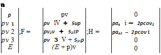
The 3D unsteady transonic fbw of an ideal gas is described by the Euler equations, represented as conservation laws in an arbitrary Cartesian coordi­nate system, rotating with the constant angular velocity uo (see Gnesin and Rzadkowski 2000):

Подпись: n p pv 0 pv 1 pv lV + 5up pae і — 2pcov2 pv 2 ;F = pv2v + 52ІР ;H = pae2 — 2pcovi pv 3 pv 3 V + 53ip 0 E (E + p)v 0

Подпись: (3) compo Here p and p are the pressure and density; tq, vs are the velocity

nents; aei and ae2 are the transfer acceleration projections; e = P U + r2a;2 is the total energy of volume unit; є is an internal energy of mass unit; r is the distance from the rotation axis.

The above system of equations is completed by the perfect gas state equation

Р = є(х~ 1),

where x denotes the ratio of the fhid specific heats.

The spatial solution domain is discretized using linear hexahedral elements.

The 3D Euler equations are integrated on moving H-H (or H-O) – type grid with use of explicit monotonous second – order accuracy Godunov – Kolgan difference scheme.

Test Stand

To realize fl>w about the vane cascade with prescribed velocities and angles of attack, the cascade was placed in a wind tunnel (Figures 1, 2 ) in which Mach numbers up to 0.7 could be attained. The four central vanes in the cas­cade were secured to individual vibration units and could undergo prescribed vibrations with two degrees of freedom. Since there was some mechanical coupling even with vibration-proofing elements between the units, it was nec­essary to keep the vibrations in all of the units steady (whether there was a fbw or not) in order to prevent this coupling from affecting the measurement results. Proceeding on the basis of this requirement, we employed an eight – channel feedback system to automatically control the vibrations of the vanes (vibration units). The system also controls the voltages and, thus, the forces on the vibrator coils so as to reduce the difference between the signal of the master oscillator and the vane vibration signal obtained in each channel (the equipment used was described in more detail in Tsymaluk 1996).

Test Stand

Figure 1. Test stand

The considered cascade consists of 9 airfoils. The central three were fas­tened cantilever on the individual vibro-unit (see Figure 3), they could ac­complish assigned displacements, aerodynamic loads were measured on them. Such airfoils are called active. An elastic suspension was designed for vanes that has two elastic elements of different widths. The auxiliary (narrow) elas-

Test Stand

Figure 2. Linear Test Facility, 1 – nuzzle wall; 2 – Pito tube; 3 – blade; 4 – airfoil; 5,8 – outlet rotary screens; 6 – rotary disk; 7 – openings for static pressure release

tic element does not impede the twisting of the main (wide) element about its own longitudinal axis, and during fexural vibrations the two elements form an elastic parallelogram. This setup ensures constant vibration parameters along the vane. The unit just described also makes it possible to change the natu­ral frequencies of the suspension by using replaceable main elements differing only in thickness.

Test Stand

Figure 3. Structure of the airfoil fhxible suspension 1 – airfoil; 2 – voice coil of the vibrator; 3 – elastic elements; 4 – strain gages

There were used three active airfoils to asset aerodynamic loads on initial airfoil (n=0), which were induced by vibration of airfoils -2, using designed experimental workbench. This could be accounted for periodicity of inflience of airfoil n = -1onn=1 one to be the same as for n = -2 on n = 0, inflience of n = 1 airfoil on n = -1 – the same as for n = 2 on n = 0 airfoil.

In accordance with developed method, the required vibrations were induced for every active airfoil. The first harmonic of the unsteady aerodynamic force and moment was measured on them. It should be noted, that determined un­steady aerodynamic forces and moments, and thus aerodynamic influence co­efficients (AIC) were related to the center of airfoil chord, about which its angular displacement occurred.

Подпись: y 4 - 2 0 00 Подпись: 05 Подпись: 10 Подпись: 15 Подпись: 20 Подпись: 25 Подпись: 30 Подпись: 35 Подпись: 40 Подпись: 45 Test Stand

The geometrical characteristics of the compressor cascade and oscillation regimes are presented by Tsimbalyuk et al. 2002. The blade length L=0.069 m, the chord length b= 0.05 m, the circular camber 10o, the thickness-to chord ration 0.07, the stager angle 60 deg., pitch-to – chord ration 0.78, the inlet Mach number 0.12 -0.35, the vibration amplitude ho =0.0007 m, ao =0.0084 rad. The cross-section of the blade is presented in Figure 4.

Figure 4. Airfoil coordinates, solid line-suction side, dashed line – pressire side

In order to calculate the AIC the vibrations of airfoils were induced by turns. The vibration amplitude of the blade was almost invariable along its length and equal to и = 85.85 Hz, which is equal to the natural frequency of the system.

EXPERIMENTAL AND NUMERICAL INVESTIGATION OF 2D PALISADE FLUTTER FOR THE HARMONIC OSCILLATIONS

Vladymir Tsimbalyuk, Anatoly Zinkovskii

Institute for Problems of Strength, Ukrainian National Academy of Sciences Ukrainian National Academy of Sciences, 2 Timiriazevskaia str., 01014 Kiev, Ukraine tsymb@yahoo. com

Vitaly Gnesin

Department ofAerohydromechanics, Institute for Problems in Machinery

Ukrainian National Academy of Sciences, 2/10 Pozharsky st., Kharkov 310046, Ukraine

gnesin@ipmach. kharkov. ua

Romuald Rzadkowski, Jacek Sokolowski

Institute ofFluid-Flow Machinery, Polish Academy ofSciences 80-952 Gdansk, ul. Fiszera 14, Polish Naval Academy z3@imp. gda. pl

Abstract The verification of the computational models for unsteady fbws through the os­cillating blade row becomes more difficult, because the experimental data for three-dimensional fbws are currently hardly available in the published litera­ture. Therefore comparisons between numerical methods and experimental ones for simple cascade geometry at inviscid flaw conditions must play an essential role in validation of the three – dimensional unsteady solution methods. In this study the numerical calculations were performed to compare the theoretical re­sults with experiments for the harmonic motion. The calculations were carried out for the torsional and bending oscillations of the compressor cascade. The comparison of the calculated and experimental results for different conditions of the cascade oscillations has shown the good quantitative and qualitative agree­ment.

Keywords: flitter, inviscid, blades

53

K. C. Hall et al. (eds.),

Unsteady Aerodynamics, Aeroacoustics and Aeroelasticity of Turbomachines, 53-63. © 2006 Springer. Printed in the Netherlands.

1. Introduction

Cases of flitter-type instability are sometime encountered in the course of developing new gas turbine engines. Costly testing is necessary to eliminate this problem. One of the main problems in predicting flitter at the engine de­sign stage is determining the transient aerodynamic loads that develop during the vibrations of blades. This problem is particularly important in the case of separated fl»w, when theoretical methods of determining the transient aerody­namic loads are not yet sufficiently reliable. Thus, in this study, we use an experimental method of determinate the transient aerodynamic loads on the vibrating blades of turbine engine.

It is quite difficult to measure the aerodynamic loads along the blades during rotation of the blading ring. Thus, with allowance for the three-dimensional nature of the air fbw about the ring, the cylindrical sections of the ring are often modeled as vane cascades. When such a cascade is placed in a wind tunnel, the fl>w parameters, geometric characteristics, and vibration parameters should be constant along the vanes.

The aeroelastic results of bending vibrations of 2D linear cascade in sub­sonic fl>w were published by Kaminier and Stel’makh 1996 and torsional Kaminier et al. 1988. The experimental results of aero-damping and dynamic stability of compressor cascades under bending-torsional vibrations were pre­sented in Len et al. 1986.

Useful benchmark data, which became a de facto standard for unsteady cas­cade fl>ws, can be found in Bolcs and Fransson 1986 for the EPFL series of Standard configurations.

Aerodynamic loads are measured indirectly either through the aerodynamic damping of bladed vibrations by Kaminier and Nastenko 1973 or the distribu­tion of transient pressures on the blade surfaces Tanaka et al. 1984. They are measured directly with an extensometric dynamometer Kimura and Nomiyama 1988 or on the basis of the forces developed by vibrators Kaminier at el. 1988.

In the Institute for Problem of Strength of NAS of Ukraine the proper 2D experimental bench was developed to measure simultaneously unsteady aero­dynamic force and moment with arbitrary combinations of motions y and a of airfoil cascades in the subsonic flow. Description of such test bench is given in paper Tsimbalyuk et al. 2002.

Summary & Conclusions

This paper presents an extension to the traditional Panovsky-Kielb for flit­ter analysis of LPT blades that considers the cyclic symmetry mode shapes. As demonstrated in the example problems this new cyclic symmetry method produces aerodynamic damping results that are in reasonable agreement with those of complete three-dimensional viscous CFD method. It does not require any additional input information or CFD analysis. The work due to the interac­tion effects of the cosine and sine modes was generally found to be significant, even for some nearly pure real modes. In addition, the work associated with the steady pressure was also found to be significant.

Acknowledgement

The authors wish to acknowledge GE Aircraft Engines for financial support and for the permission to publish this work. The authors also express gratitude to Francesco Poli (University of Florence) and Claudia Schipani (Fiat Avio) for their cooperation on the test cases.

References

Arnone, A, Poli, F., and Shipani, C., 2003, A Method to Assess Flutter Stability of Complex Modes, Accepted for Presentation at the 10th ISUAAAT, Duke University, September 2003

Chernycheva, O. V., Fransson, T. H., Kielb, R. E., and Barter, J., 2001, ’’Comparative anal­ysis of blade mode shape infhence on flitter of two-dimensional turbine blades”, ISABE – 2001-1243, XVISOABE conference, September 2-7, Bangalore, India

Kielb, R. E., and Barter, J., Chernycheva, O. V., and Fransson, T. H., 2003, ’Flutter of Low Pressure Turbine Blades with Cyclic Symmetric Modes – A Preliminary Design Method”, presented at ASME Turbo Expo 2003, June 2003, Atlanta, Georgia, accepted for publica­tion in the ASME Journal of Turbomachinery.

Panovsky J., and Kielb R. E., 1998, “A Design Method to Prevent Low Pressure Turbine Blade Flutter”, 98-GT-575, ASME Gas Turbine Conference and Exhibition, Stockholm, Sweden