Category UNSTEADY AERODYNAMICS, AEROACOUSTICS AND AEROELASTICITY OF TURBOMACHINES

Analysis Methodology

Since one of the aims of this work was to study the infbence of the torsion centre for different reduced frequencies and configurations it was decided to follow a simplified design approach (Panovski and Kielb, 2000). The basic

Analysis Methodology

Analysis Methodology

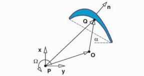
Figure 2. Description of the blade motion as a rigid body


idea is to assume that the main contribution to the aerodynamic damping is due to the actual blade and the two neighbouring blades. In this case the aero­dynamic damping varies sinusoidally with the inter-blade phase angle and it may be computed with as few as three linear computations. The validity of such approach has been shown both experimentally (Nowinski and Panovski, 2000) and numerically (Panovski and Kielb, 2000).

Following the approach of Panovski and Kielb (2000) just the unsteady pres­sure field associated to the bending in the x and y direction and the torsion about a given point, P, for a reference displacement are computed. The un­steady pressure associated to the motion of the airfoil as a rigid body about an arbitrary torsion axis, O, is computed as a linear combination of three refer­ence solutions. The velocity of an arbitrary point, Vq, of the airfoil is of the form:

Vq(t) = Vp(t) + fi(t)k x PQ (7)

where fi is the angular velocity of the airfoil, k is the unit vector perpendicular to the xy plane. Choosing VP and fi properly it is possible to make an arbitrary point O the torsion axis, this condition is

Vo(t) = Vp(t) + fi(t)k x PO = 0 (8)

and hence is enough to satisfy Vp = —fik x PO for an arbitrary fi. We may write Vp = vx i + vyj where

vx = exwRe [ihx, ref elwtj and vy = eywRe (ihy>ref elwtj (9)

and ex and ry are scaling factors of the actual displacements with respect the ones of reference hx ref and hy, ref. Analogously

Подпись:a = r^Re (aref elut) and fi = r^wRe (iaref elut) .

The unsteady pressure perturbation, p due to the motion of the airfoil as a rigid body is assumed to behave linearly and therefore it may be expressed as the sum of the unsteady pressure fields associated to bending in the x direction, p’Vx, bending in the у direction, p’ , and torsion about the point P, p’n, i. e.:

Pf = Pvx + Pvy + Pn = exPvx, ref + eyPvy, ref + enPn, ref – (H) The work per cycle over the airfoil, W, is

р2тг/и r

w= / p’Vq. dAdt (12)

Jo Jy, c

Подпись: 0 Подпись: W peUedmaxucH Подпись: { ex ey } Подпись: Wx,y wx,Q 1 Wy,x wy,y ЄУ VJQ,n ref v ед

where is the velocity of the blade surface. W > 0 means that the blade motion is damped by the aerodynamics. Substituting equations 7 and 11 in 12 it is possible to obtain the following expression for W in non-dimensional form:

where each element of work coefficient matrix represents the non-dimensional work obtained combining each unsteady pressure field with on the displace­ments of each mode (e. g. wx^ is the work perform by the unsteady pressure associated to the airfoil bending in x on the displacements due to the torsion about point P), pe and Ue are, respectively, the density and velocity at the cas­cade exit, dmax is the maximum airfoil displacement in the reference cases and cH is an estimate for the airfoil surface.

The work coefficient matrix [w] is calculated once for each IB FA of the fun­damental modes. The general procedure is then to run the unsteady code in the three fundamental modes with a reference amplitude through the range of inter-blade phase angles. As few as three inter-blade phase angles per funda­mental mode need to be used. The rest of IB FA are obtained assuming that w = a + b sin a + c cos a. The critical IB FA is computed then as the minimum of the previous expression.

In this work we have obtained the values of the damping coefficients for a = 0° and a = ±90° to estimate the whole range of inter-blade phase angles. The errors associated to this approximation may be seen in figure 3 where the damping coefficients for the edgewise, fhp and torsion modes for different reduced frequencies are displayed. It may be appreciated that the damping coefficient curves of the edgewise and fhp modes have a sinusoidal form. This is specially true for к = 0.1 while for к = 0.4 two spikes, corresponding to resonant conditions, are superimposed to the sine-like shape. This behaviour

Analysis Methodology

Figure 3. Damping as a function of IBPA for the three fundamental modes. Top: single blade configuration. Bottom: Welded-pair configuration

is as could be expected since it is well known that the relative inflience of the adjacent blades to the reference one decreases when the reduced frequency is increased (see Corral & Gisbert (2002) for example). The deviations from the sinusoidal from of the torsion mode are larger, but in all the cases the critical interblade phase angle is still well predicted.

Numerical Formulation Linearized Euler Equations

A two-dimensional cascade of blades vibrating sinusoidally with a small amplitude, common angular frequency, cj, and common inter-blade phase – angle, a, may be modeled within engineering accuracy by the linearized Euler equations if the fbw remains attached along the airfoil.

The two-dimensional Euler equations in conservative form for an arbitrary control volume may be written as:

Numerical Formulation Linearized Euler Equations(1)

where U is the vector of conservative variables, f and g the inviscid fbxes, ft the fbw domain, E its boundary, dA the differential area pointing outward to the boundary and V the velocity of the boundary. Now we may decomposed the fbw into two parts: a steady or mean background fbw, plus a small but

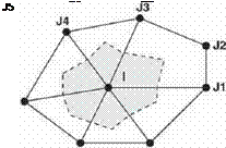
Figure I. Typical hybrid-cell grid and associated dual mesh

periodic unsteady perturbation, which in turn may be expressed as a Fourier series in time. If we retain just the first harmonic any variable may be expressed as:

U(x. t) = Uq(x) + Re(u(x)e, u’!’) (2)

where Uo represents the background flbw and u is the complex perturbation. The Euler equations may then be linearized about the mean fbw to obtain:

Подпись: au ’ да dAПодпись: tut J U0x'.rfA(——Ь ioj) I xidQ +

Jn

Подпись: (fo.goMA'

Numerical Formulation Linearized Euler Equations

ioj I Uo dtf +

Jn

which is a linear equation of complex coefficients and where the first term is an additional time-derivative added to solve the equations marching in the pseudo-time r.

Spatial Discretization

The code known as Mu2s~T — L solves the two-dimensional linearized Euler equations (3) in conservative form. The spatial discretization is ob­tained linearizing the discretized equations of the non-linear version of the code Mu2s2T (Corral and Gisbert, 2002), from which the background solu­tion is obtained. The spatial domain is discretized using hybrid unstructured grids that may contain cells with an arbitrary number of faces and the solution vector is stored at the vertexes of the cells. The code uses an edge-based data structure, a typical grid is discretized by connecting the median dual of the cells surrounding an internal node (Figure 1). For the node і the semi-discrete form of Eq 3. can be written as
where Sij is the area associated to the edge ij, and nedges the number of edges that surround node j. The resulting numerical scheme is cell-centered in the dual mesh and second-order accurate. It may be shown that for triangular grids the scheme is equivalent to a cell vertex finite volume scheme. A blend of second and fourth order artificial dissipation terms, D^, is added to capture shock waves and prevent the appearance of high frequency modes in smooth fbw regions respectively. The second order terms are activated in the vicinity of shock waves by means of a pressure-based sensor and locally the scheme reverts to first order in these regions. The artificial dissipation terms can be written as

Подпись: (5)

Numerical Formulation Linearized Euler Equations

bij = IAij I Sij fif (uj – ui) – (Lj ~ Li)] (5)

Numerical Formulation Linearized Euler Equations

where /jy^ and are the average of the artificial viscosity coefficients in the nodes і and j, L is a pseudo-Laplacian operator:

where the last approximation is only valid in regular grids and | Aij | is a 4 x 4 matrix that plays the role of a scaling factor. If |A^ | = (|u| + c)ij I, where I is the identity matrix, the standard scalar formulation of the numerical dissi­pation terms (Jameson et al., 1981) is recovered. When Aij is chosen as the Roe matrix (1981) the matricial form of the artificial viscosity (Swanson and Turkel, 1992) is obtained. The scalar version of the numerical diffusion terms has been used in this work since for the Mach numbers of interest in this work the differences between both approaches are negligible (Corral et al. 2000).

The exact, 2D, unsteady, non-refbcting boundary conditions (Giles, 1990) have been used at the inlet and outlet while the phase-shifted boundary con­ditions at the periodic boundaries are written in Fourier space as u{x, y + pitch) = u(x, y)ela.

A more detailed description of the code as well as some validation examples may be found in Corral et al. (2003)

FLUTTER BOUNDARIES FOR PAIRS OF LOW PRESSURE TURBINE BLADES

Roque Corral,1,2 Nelida Cerezal, 2 and Carlos Vasco 1

1Industria de Turbopropulsores SA

Parque Empresarial San Fernando, 28830 Madrid

Spain

roque. corral@itp. es

2

School of Aeronautics, UPM Plaza Cardenal Cisneros 3, 28040 Madrid Spain

Abstract The aerodynamic damping of a modern LPT airfoil is compared to the one ob­tained when pairs of blades are forced to vibrate as a rigid body to mimic the dynamics of welded-pair assemblies. The stabilizing effect of this configuration is shown by means of two-dimensional simulations.

The modal characteristics of three bladed-disk models that differ just in the boundary conditions of the shroud are compared. These models are representa­tive of cantilever, interlock and welded-pair designs of rotating parts. The differ­ences in terms of frequency and mode-shape of the three models are sketched. Finally their relative merits from a flitter point of view are discussed using the 2D aerodynamic damping characteristics.

Keywords: Flutter, Low Pressure Turbine, Stability Map

Introduction

Flutter has been a problem traditionally associated to compressor and fan blades. However the steady trend during the last decades to design high-lift, highly-loaded low pressure turbines (LPTs), with the final aim of reducing their cost and weight, while keeping the same efficiency, has lead to a reduction of the blade and disk thickness and an increase of the blade aspect ratio. Both factors tend to lower the stiffness of the bladed-disk assembly and therefore its natural frequencies.

As a result of the afore mentioned evolution vanes and rotor blades of the latter stages of modern LPTs of large commercial turbofan engines, which may

3

K. C. Hall et al. (eds.),

Unsteady Aerodynamics, Aeroacoustics and Aeroelasticity of Turbomachines, 3-16. © 2006 Springer. Printed in the Netherlands.

be designed with aspect ratios of up to six, may potentially flitter and undergo alternate stresses similar to the ones encountered in fans and compressors.

Vibration control of shrouded LPT blades may be accomplished using either cantilever, inter-lock or welded-pair configurations. Flat sided shrouds may vi­brate freely even for very small clearances specially for low inter-blade phase angles (IBFA) and provide little control over the vibration characteristics of the bladed-disk. To remedy this deficiency z-shaped shrouds (interlocks) were de­signed with the aim of remaining tight during the whole fight envelope. This type of designs significantly modify the vibration characteristics of cantilever blades, however, the mode-shapes of a given family may significantly vary with the nodal diameter and induce bending-torsion coupling. Finally, pairs of blades welded in the tip-shroud, were devised as a practical alternative to control the vibration characteristics of LPT bladed-disks and may be seen in some turbofan engines. This latter configuration substantially modifies as well the mode-shapes and frequencies of the baseline (cantilever) and interlock so­lutions.

It is well known that flitter boundaries are very sensitive to blade mode – shapes and that the reduced frequency plays a secondary role. A comprehen­sive numerical study of the infbence of both parameters for LPT airfoils was performed by Kielb & Panowski (2000) and supported by experimental work (Nowinski and Panovski, 2000). The aim of this work is to investigate the infbence of pairing the blades in the aerodynamic damping of a typical LPT section and apply the results to a realistic configuration to elucidate the po­tential benefits of such configurations in the modal behaviour of bladed-disk assemblies.

Unsteady Aerodynamics, Aeroacoustics and Aeroelasticity of Turbomachines

Over the past 30 years, leading experts in turbomachinery unsteady aerodynamics, aeroa- coustics, and aeroelasticity from around the world have gathered to present and discuss recent advancements in the field. The first International Symposium on Unsteady Aerody­namics, Aeroacoustics, and Aeroelasticity of Turbomachines (ISUAAAT) was held in Paris, France in 1976. Since then, the symposium has been held in Lausanne, Switzerland (1980), Cambridge, England (1984), Aachen, Germany (1987), Beijing, China (1989), Notre Dame, Indiana (1991), Fukuoka, Japan (1994), Stockholm, Sweden (1997), and Lyon, France (2000). The Tenth ISUAAAT was held September 7-11, 2003 at Duke University in Durham, North Carolina. This volume contains an archival record of the papers presented at that meeting.

The ISUAAAT, held roughly every three years, is the premier meeting of specialists in turbomachinery aeroelasticity and unsteady aerodynamics. The Tenth ISUAAAT, like its predecessors, provided a forum for the presentation of leading-edge work in turbomachinery aeromechanics and aeroacoustics of turbomachinery. Not surprisingly, with the continued development of both computer algorithms and computer hardware, the meeting featured a number of papers detailing computational methods for predicting unsteady flows and the resulting aerodynamics loads. In addition, a number of papers describing interesting and very useful experimental studies were presented. In all, 44 papers from the meeting are published in this volume.

The Tenth ISUAAAT would not have been possible without the generous financial support of a number of organizations including GE Aircraft Engines, Rolls-Royce, Pratt and Whit­ney, Siemens-Westinghouse, Honeywell, the U. S. Air Forces Research Laboratory, the Lord Foundation of North Carolina, and the Pratt School of Engineering at Duke University. The organizers offer their sincere thanks for the financial support provided by these institutions. We would also like to thank the International Scientific Committee of the ISUAAAT for se­lecting Duke University to host the symposium, and for their assistance in its organization. Finally, the organizers thank Loraine Ashley of the Department of Mechanical Engineering and Materials Science for her Herculean efforts organizing the logistics, communications, and finances required to host the conference.

The Eleventh ISUAAAT will be held in Moscow, Russia, September 4-8, 2006, and will be hosted by the Central Institute of Aviation Motors. Dr. Viktor Saren, the hosting member of the International Scientific Committee, will serve as deputy chair of the symposium; Dr. Vladimir Skibin, the General Director of CIAM, will serve as chair.

Kenneth C. Hall Robert E. Kielb Jeffrey P. Thomas

Department of Mechanical Engineering and Materials Science Pratt School of Engineeering