Category UNSTEADY INCOMPRESSIBLE POTENTIAL FLOW

Solution by the Time-Stepping Method

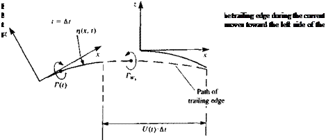
The above presentation of the thin-airfoil fluid dynamics is formulated as an initial-value problem. Typical initial conditions can be a steady-state motion or a start from rest. In the latter case there is no wake at t = 0 and the first wake element is formed at t = At. Consider the airfoil after the first time step At, as shown in Fig. 13.17a. The problem at this moment is to obtain the flow field details and to calculate the pressure difference across the airfoil, in the presence of one wake vortex—which represents the vorticity shed at the trailing edge since the initiation of the motion. To apply the results of the small-disturbance solutions of Sections 5.2-5.3, the airfoil’s camber and angle of attack are assumed to be small, rj/c «1, and the path curvature must be large (вс/и«1), so that the boundary conditions can be transferred to the z=0 plane. If the lifting thin airfoil is modeled by a chordwise vortex distribution y(x, t), then at the first time step this problem resembles exactly the model shown in Fig. 5.7, but with an additional wake vortex Гщ (Fig. 13.17a). The downwash induced by the airfoil bound circulation y(x, t) is

(a)

Location of T. E. at t = 0

Solution by the Time-Stepping Method image591 Подпись: (13.54a)

given by Eq. (5.38) (note that the boundary conditions are transferred to the 2 = 0 plane):

At any later time the downwash of the Nw discrete vortices of the wake (see Fig. 13.17b) on the airfoil can be summed numerically by using, for example, Eq. (11.1):

Подпись: (13.54b)5Фіу, v _ v ^____________ X Xk_______

52 2n (x – xkf + (z-zkf

where к is the counter of the wake vortices. The downwash of the bound vortex distribution of Eq. (13.54a) must be equal to the right-hand side of the boundary condition in Eq. (13.50):

Подпись: ЭФц/ dz image592"

Подпись: 6x dt Solution by the Time-Stepping Method

■ dn вх+ — dt

where the smaller terms were neglected. Substituting this approximate value of W(x, t) and dФв|dz from Eq. (13.54a) into the boundary condition (Eq.

0<*<c (13.56)

image593

(13.50)) results in

which is the time-dependent equivalent of the steady-state boundary condition (Eq. (5.39)) and must hold for each point x on the airfoil’s chord. In addition, the Kutta condition is assumed to be valid for this flow (recall that вс/U « 1):

У(с,0 = 0 (13.57)

If the right-hand side of Eq. (13.56) is known then the solution for the vortex distribution is given in Section 5.3. In fact, all terms appearing in the right-hand side are known (will have numeric value) at any time t, excluding the latest wake vortex influence, which depends on the solution y(x, t). This difficulty can be overcome by assuming that the strength of the latest wake vortex is known, too, and adjusting for this assumption later.

The classical approach of Glauert, presented in Section 5.3, approximates y(x, t) by a chordwise trigonometric expansion at any time t. This requires the transformation of the equations into trigonometric variables as appear in Eq.

(5.45) :

Подпись: (13.58)Q

x = – (1 — cos d)

Based on this transformation, a solution similar to the vortex distribution of Eq. (5.48) is proposed for the time-dependent problem (at each frozen moment, t):

y(#, t) = 2U(t)[A0(t) ~ + C^ + 2 An(t) sin (nt?)l (13.59)

Substituting this proposed solution into the boundary condition (see details in Section 5.3, Eqs (5.49)-(5.53)) results in

= – Ло(0 + S An(t) cos (n#) (13.60)

Ut) n = l

Подпись: A, Solution by the Time-Stepping Method Solution by the Time-Stepping Method

which is a trigonometric expansion of the momentary chordwise downwash. The coefficients An were found in Section 5.3 (Eqs. (5.51) and (5.52)) and are:

So at this point, if the momentary chordwise downwash W(де, t) is known then the momentary circulation distribution on the airfoil is known, too, from Eqs. (13.59), (13.61), and (13.62). However, as mentioned before, the strength of the latest vortex (Fig. 13.176) in the downwash term is unknown, but it can be calculated by using Kelvin’s condition (Eq. (13.51)). A simple iterative scheme to calculate the strength of this vortex is as follows: at a given time step assume that the strength of the latest vortex Гis known (0 or Г(ґ)/2 are reasonable initial assumptions). Then the total circulation (which must be zero for the converged solution) can be expressed as

,_i f for the ]

/(Г) = Г(/) + TW: + 2 TWk j =0 converged r (13.63) *-1 [_ solution J

where the first term is the airfoil’s circulation, the second term is the latest wake vortex, and the last term is the circulation of all the other wake vortices (which are known from the previous time steps). The circulation of the airfoil is obtained by using Eq. (5.58):

Г(0 = f y(x, t)dx= f y(0, t) ^ sin 0 dt?

Jo Jo 2

= 2U(t) f [a0(0 1 + C°^ + 2 A„(t)sin (ntf)l C-sin fldtf Jo L sin 17 n~ J 2

= (/(0ся[ло(0+^] (13.64)

The iterations for determining the strength of the latest vortex element (using a simple Newton-Raphson iteration) will have the form

(Ги’)у+і = (Гил)/ – 777^ (13.65)

/ l wjj

where j is the iteration counter and the derivative /'(Г) is approximated by

r(r) _№)>-/(Г)/-:]

‘ (^-(Г^

The solution of the momentary airfoil’s vortex distribution Г(г) can be summarized such that, first, at a given time step t, the downwash W(x, t) is calculated by Eq. (13.55). By assuming an initial vortex strength TWj for the most recently shed trailing edge vortex the wake influence is calculated via Eq. (13.546). So now the chordwise downwash W(jc, t) can be calculated at any point along the chord and, for example, can be evaluated at say 50 nodal points on the chordline. This allows the numerical computation of the coefficients An(t) and /(Г) (in Eqs. (13.61)-(13.63)). Then using Eq. (13.65) the next value of the latest wake vortex is obtained, and this short iterative process (beginning with the downwash calculation and ending with the value of
the chordwise vortex distribution) is repeated. This simple iteration scheme will usually converge within 3-5 iterations and this will conclude the solution of the vortex distribution for this time step.

Wake Model

Подпись: FIGURE 13.15 Discretization of the wake’s continuous vortex distribution by the use of discrete vortices.

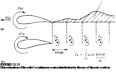
As was discussed in Sections 4.7 or 13.3, the wake shed from the trailing edges of lifting surfaces can be modeled by doublet or vortex distributions. In the two-dimensional case the unsteady airfoil’s wake will be shed only if the airfoil’s circulation varies with time (Kelvin’s condition). Therefore, if the airfoil circulation is varying continuously, then a continuous vortex sheet will be shed at the trailing edge, as shown in Fig. 13.15a. For simplicity, a discrete vortex model of this continuous vortex sheet is approximated here, as shown in

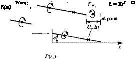
Fig. 13.15ft. The strength of each vortex IV is equal to the vorticity shed during the corresponding time step At such that Г^ = yw(t)U(t) dt. Consequently, for each vortex element, its strength and location must be specified. In regard to specifying wake-vortex location, consider the first wake element after the beginning of the motion, as shown in Fig. 13.16. The wake was “probably” shed at the airfoil’s trailing edge, which moved during the latest time step along the dashed line. (Note, again, that in this figure the fluid is stationary and the airfoil moves to the left!). So at first estimate it will be placed on this line. The distance and relative angle to the trailing edge are important numerical parameters, and usually the wake vortex location should be aligned with the trailing edge and be placed closer to the latest position of the trailing edge. (This is so, since the discrete vortex when placed at the middle of this interval is an approximation that underestimates the induced velocity when compared with the continuous wake vortex sheet result. This is mainly due to the small distance (zero distance) of the continuous wake from the trailing edge during the time interval, compared to the relatively larger distance of an equivalent discrete vortex with similar vorticity placed amid the interval of the latest time step. A typical numerical approach to correct for this wake-discretization error is to place the latest vortex closer to the trailing edge (e. g., within the range of 0.2-0.317(f) At as shown schematically in Fig. 13.16).

The strength of the latest vortex element is calculated by using Kelvin’s condition (Eq. (13.6)), which states that

Подпись: (13.51)

image590

dr dT(t) | dTw dt dt dt

where T(f) is the airfoil’s circulation and is the wake’s circulation,
respectively. For the first time step

Г(0 + = 0

and for the ith time step

= (13.52a)

or by assuming that the Kelvin condition was met at the previous time step then

L-[r((,)+ELt] (13.52*)

It must be noted, too, that the Helmholtz theorems of Section 2.9 imply that there is no vortex decay. That is, if a wake vortex element is shed from the trailing edge its strength will be conserved (which is a good practical approximation for most high Reynolds number flows).

Since the vortex wake is force-free, each vortex must move with the local stream velocity (Eq. (13.21a)). The local velocity is a result of the velocity components induced by the wake and airfoil (wing), and is usually measured in the inertial frame of reference X, Z. To achieve the vortex wake rollup, at each time step the induced velocity (и, w), is calculated and then the vortex elements are moved by

(Ддг, Az), = (и, w), At (13.53)

In this simple scheme the velocity components and vortex positions of the current time step are used. But more refined techniques can be applied here that may improve the wake shape near the trailing edge (by using information from the current and previous time steps).

Kinematics

In Section 13.1 (Eq. (13.12)) it was shown that the continuity equation in the moving frame of reference x, z remains as:

V2<D = 0 (13.42)

where Ф is the equivalent of the steady-state perturbation potential.

The time-dependent version of the boundary condition requiring no
normal flow across the surface is given by Eq. (13.13a):

(УФ – V0 – vrel – Я X r) • n = 0 (13.43)

In this section the instantaneous shape of the airfoil is given by rj(x, t) and therefore the vector n normal to the surface is

Подпись: n =image588(13.44)

To establish the kinematic relations for the airfoil’s motion (according to Eq. (13.8)) the instantaneous velocity and orientation of the x-z system can be described by a flight velocity U(t) and a rotation 6 about the у coordinate. Note that the x coordinate was selected such that the instantaneous velocity of the origin ( )o (of Eq. (13.9a)) resolved into the directions of the x-z coordinate system is

Vo = [-t/(f), 0,0] (13.45)

The instantaneous rotation is then

Si = [0,0(0,0] (13.46)

Подпись: Vrel Подпись: ) Подпись: (13.47)

Also, by allowing a relative motion of the camberline within the coordinate system x-z the relative velocity of Eq. (13.9c) becomes

At this point, it is convenient to divide the velocity potential Ф into an airfoil potential Фв and to a wake potential Ф№ (for example, if a time­stepping numeric approach is used, then the strengths of the wake singularities are assumed to be known and only the airfoil’s singularity distribution Фв must be obtained):

Ф = Фв + Фи, (13.48)

Evaluating the product

Si X r = (6z, 0, — Qx)

and substituting Eqs. (13.45)-(13.47) into the boundary condition (Eq. (13.43)) results in

^ ox ox dz dz

This can be rearranged in terms of the boundary condition for the unknown

Подпись: ЭФВ dz Kinematics Подпись: ЭФу dz Подпись: дп вх + — = W(x, t) Подпись: (13.50)

potential Фв:

The main advantage of this formulation lies in the previous assumption that if the wake potential is known (and it is usually known from the previous time steps, when a time-stepping solution is applied) then the solution can be reduced to solving an equivalent steady-state flow problem, at each time step. For example, if this model is compared to the thin, lifting airfoil of Section 5.2 then the boundary condition of Eq. (13.50) is equivalent to the steady-state boundary condition of Eq. (5.29). Therefore, by exchanging the local downwash W(x, t) with the right-hand side of Eq. (5.29), the methods of solution developed in Chapter 5 can be applied at each moment. Also, note that the boundary condition (Eq. (13.50)) is not reduced to its small disturbance approximation yet and can be specified (numerically) on the airfoil’s surface and not on the z = 0 plane.

UNSTEADY MOTION OF A TWO – DIMENSIONAL THIN AIRFOIL

As is indicated in Section 13.6, steady-state flow methods can be extended to treat the time-dependent problem with only a few modifications. Following this methodology, the time-dependent equivalent of the small disturbance, thin,

image587

FIGURE 13.14

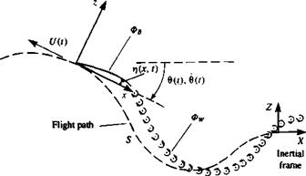
Nomenclature for the unsteady motion of a two-dimensional thin airfoil (note that the motion is observed from the X, Z coordinate system and the airfoil moves toward the left side of the page).

lifting airfoil in steady flow (Sections 5.2-5.4) is treated in this section. One of the more difficult aspects of this unsteady problem is the modeling of the vortex wake’s shape and strength, which depends on the time history of the motion. By selecting a discretized vortex wake model at the early stages of this discussion we limit ourselves mostly to numerical solutions. But it seems that this approach allows for a simple formulation (which is clear and easy to explain to students) that avoids an elaborate mathematical treatment of the wake-influence integral.

The two-dimensional, thin lifting surface with a chord length of c is shown schematically in Fig. 13.14. At t = 0 the airfoil is at rest in the inertial system X, Z, and at f>0 it moves along a time-dependent curved path, S. (Note that the fluid in Fig. 13.14 is basically at rest and the airfoil moves toward the left of the page!) For convenience, the coordinates x, z are selected such that the origin is placed on the path S, and the x coordinate is always tangent to the path. The airfoil shape (camberline) is given in this coordinate system by ij(jc, f), which is considered to be small {rj/c « 1). Since small-disturbance motion is assumed, the path radius of curvature g is also much larger than the chord c (or c/g = dc/U(t)« 1).

The Added Mass

In situations when a body is accelerated in a fluid, it is possible to use Newton’s second law, in its most simple form, to compute the force F acting on the body. For example, if the body motion is parallel to the 2-axis then:

Of course the mass mto, consists of the mass of the body m, and of the fluid m’ that is being accelerated as well. Unfortunately, the evaluation of the added mass (m’) is not always easy since in most situations the local fluid acceleration may be caused by effects other than the body’s motion (e. g., in the case of a time-dependent wake-induced downwash). But in the case of a constant acceleration of a flat plate normal to itself, in a fluid at rest, the added mass can be more easily evaluated (see also Section 8.2.3).

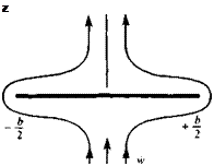
Consider the flat plate of Fig. 13.12 accelerating in a fluid, such that the acceleration w is constant (see also Fig. 8.24). Since the continuity equation is independent of time, at each frozen moment the potential will be similar to the steady-state flow potential of the flow normal to the plate. From Section 6.5.3 the potential for such a flow is

image581(13.38)

Подпись: z
image582
Подпись: У The Added Mass

where + is used for the potential above the plate and – is used for the potential below it. This is an elliptic distribution of the potential, similar to the

FIGURE 13.13

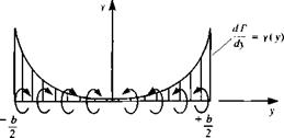
image584Spanwise circulation on a flat plate in a sinking motion.
one obtained in Chapter 8 for the lifting-line and slender-wing theories. Because of the antisymmetry between the upper and lower surfaces,

АФ(З’) = 2Ф+(у) = wb yjl – (13-39)

It is interesting to point out that АФ in this equation can be replaced by Г and its derivative is the spanwise circulation y(y) as shown in Fig. 13.13. Examining the terms in the pressure equation (Eq. (13.23)) reveals that for this motion (V0 + S2 X r) • V4> = (0,0, w) • УФ = 0 since УФ will have a у component only, on the plate’s surface. (This can be deduced from Fig. 13.13, too, by observing that the “traditional” lift уx (0,0, w) has no vertical component.) Therefore, the pressure difference is due to the velocity potential’s time derivative дФ/dt, only, in the unsteady Bernoulli equation, and is

image585,image586 Подпись: (13.41)

The integral is easily evaluated by recalling that the area of the ellipse is жЬ/4 and the lift L’ of a massless plate becomes

Note that because of the left/right symmetry, the center of pressure is at у = 0. Also, the lift is created only if the plate is under acceleration and the amount of fluid being accelerated (added mass) is equal to the mass of a fluid cylinder with a diameter of b {m’ — рЬ2(ж/4)), and in summary we can write

L’ = m’w (13.41a)

SUDDEN ACCELERATION OF A FLAT PLATE

One of the simplest and yet the most basic examples of unsteady aerodynamics is the sudden acceleration motion of an airfoil.13 2 This example will be studied first by the simple “lumped vortex” method so that the most basic differences between this case and the steady flow case will be highlighted.

Consider the thin, uncambered airfoil shown in the upper part of Fig.

13.7

Подпись: f>0
image564

to be at rest at Г <0. Then at t – 0 the airfoil is suddenly accelerated to a constant velocity (/„. The boundary condition for />0 and for small a, according to Eq. (13.30) is

Now let us represent the airfoil by a lumped vortex element. By doing so, a single vortex solution is selected instead of the more general form of Eq. (13.15) that includes doublets and sources. Also, by placing the vortex at the quarter chord, the Kutta condition is assumed to be satisfied for this case.

JV4 Af2

Э і 9 і 9 і *•) 1 ‘« = 4Аг

f і*-,

^ І Э І = 2Л’

Подпись: f/» -4Лг

image565,image566,image567

к

FIGURE 13.7

Development of the wake after the plunging motion of a flat plate modeled by a single lumped vortex element.

At this point also a wake model has to be established and here a discrete vortex wake is selected (Fig. 13.7). Now at a time = At, the airfoil already has traveled a distance t/„ At and its circulation is Г(г,). Recalling Kelvin’s theorem (Eq. (13.6)), the airfoil-bound circulation has to be canceled with a starting vortex (Fig. 13.7, at tx = At). The concentrated wake vortex has to be placed along the path traveled by the trailing edge, during this interval, so that the discretization effect will be minimal. At this point the middle of the interval is selected and the effect of this choice can be demonstrated later.

Подпись: -Г(гі)

The zero normal flow boundary condition is satisfied at the collocation point at the plate’s three-quarter chord point (as shown by the x in Fig. 13.7) where the downwash induced by the bound vortex is

and the downwash induced by the first wake vortex is approximated by

image569

assuming a« 1. The boundary condition дФ/dz = – U^a for the first time step then becomes

image570

This equation can be rewritten in the form

wb + % + U^a – 0

which indicates that the sum of the velocity induced by the airfoil wb, the wake ww and the free stream must be zero. An additional equation is obtained by using the Kelvin condition

—=^0 + ^ = 0

Note that Г is considered positive for right-hand rotation, and in Fig. 13.7 for illustration purposes and with the knowledge of the solution, the wake vortex is drawn in the negative direction.

The above set of two equations with two unknowns is solved for Г(гі) and IVj. Now, after the second time step the airfoil has moved to a new location, as shown in the figure (for t2 = 2At). It was assumed in Section 2.9 that for high Reynolds number flows vortex decay is negligible (and zero for irrotational flow) and therefore the strength of rW| will not change with time. It is possible to calculate the induced velocity at the wake vortex and then move it along the local streamline, but for simplicity it is assumed here that its location remains unchanged (in the inertial frame).

At t = 2 At, the two equations describing the “no-flow-across-the-airfoil” boundary condition and the Kelvin condition are:

image571

T(f2) + rv2 + rWl – 0

This set is solved for Г(г2) and TW2 while TWl is known from the previous calculation at t = tx.

At t = 3 At, the two equations can be written in a similar manner:

image572

Г(*з) + Гіу3 + г W2 + г Wl = о

Again this set is solved for T(f3) and Г*,,, while TW2 and TW| are known from the previous calculations.

image573

In this simplified analysis it was assumed that a is very small and the distance to the collocation points can be approximated by

and that the induced velocity is normal to the surface. Of course, numerically this error can easily be corrected.

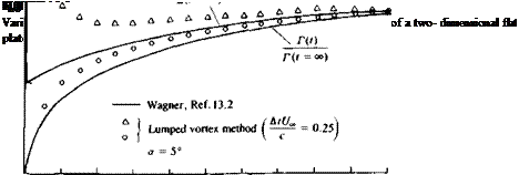
The results of this computation for Г(г) (shown by the circles), along with a more accurate solution, are presented in Fig. 13.8. The circulation at t = 0 is zero since the airfoil is still at rest. At t > 0 the circulation increases but is far less than the steady-state value due to the downwash of the starting vortex. In this two-dimensional case the increase of the circulation is slow and this transient growth extends to infinity.

image574,image575

To compute the lift, the small-disturbance approximation (V,* » |V*^|) is applied to the unsteady Bernoulli equation (Eq. (13.23)):

and the pressure difference between the airfoil’s upper and lower surface is

image576")= pU^y(x) + pjJ y(x)dx (13.35)

Here we used the results of Eq. (3.147) for a planar vortex distribution where the upper surface induced velocity is УФ = (y/2, 0, 0).

For the lumped vortex method there is only one airfoil vortex and therefore the lift L’ per unit span is

image577(13.36)

Results of this simple model (triangular symbols) along with the exact solution of Wagner13 2 are presented in Fig. 13.8. The lift at / = 0+ is exactly half of the steady-state lift, but this lift is not due to the airfoil circulation (circulatory force) but due to the acceleration portion of the lift that is a result of the change in the upwash (ЭФ/dt). The magnitude of this force due to fluid acceleration becomes smaller with the reduced influence of the starting vortex. At t = 0 when the airfoil was suddenly accelerated from rest the lift was infinite, due to this acceleration term as shown in Fig. 13.8.

Подпись: 0.025 ~i •  '  ft non. J I 1 1 1 1 1 >— 0 0 1.0 2.0 3.0 4.0 5.0 6.0 7.0 8.0

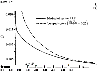
It is interesting to point out that for a two-dimensional airfoil there is a drag force during the transient. This drag force will have two components, due

9.0 v °°

l/=r

FIGURE 13.9

Varation of drag after the initiation of a sudden forward motion of a two-dimensional flat plate.

image579

FIGURE 13.10

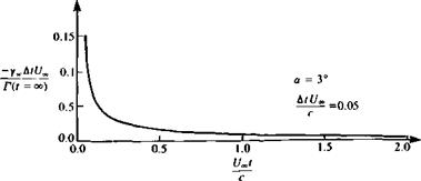
Wake circulation distribution behind the flat plate which was suddenly set into motion.

to the two terms of the lift in Eq. (13.36). The first is due to the wake-induced downwash, which rotates the circulatory lift term by an induced angle ww/(J„. The second is due to the fluid acceleration ЭФ/dt which acts normal to the flat plate and its contribution to the drag is a times the second lift term in Eq.

(13.36) . Consequently the drag force is

D = p[wv(*, f)T(r) + T(r)caj (13.37)

Here the first term is due to the wake-induced downwash ww(x, t), which in the lumped vortex case is evaluated at the three-quarter chord point. The second term is due to the fluid acceleration and its center of pressure is a function of the change in the momentary chordwise downwash, which is closer to the aft section of the airfoil and varies with time. Calculated drag coefficients with this method and with a more accurate method131 are presented in Fig. 13.9.

While examining the wake vorticity as presented in Fig. 13.10, it can be observed that the first vortices are the strongest and that all vortices have counterclockwise (negative) values. Consequently, when the wake is allowed to rollup, due to the velocity field induced by the wake and the airfoil, the shape shown in Fig. 13.11 will be obtained.

a = 3°

image580

FIGURE 13.11

Wake rollup behind a two-dimensional flat plate which was suddenly set into motion.

A simple computer program based on the formulation of this section is presented in Appendix D, Program No. 13.

SUMMARY OF SOLUTION METHODOLOGY

The results of Sections 13.1-13.4 indicate that the unsteady flow method of solution is very similar to the steady-state methods presented in the previous chapters. Therefore, it is possible to use those steady-state methods with only a few small modifications. These modifications can be limited to three sections of the analytical or the numerical model and in general are:

1. Update of the “zero normal-flow on a solid-surface” boundary condition to include the kinematic velocity components (as in Eq. (13.13a)).

2. Similarly, use of the modified unsteady Bernoulli equation (as in Eq.

3.

Подпись: (13.23)).

Construction of a wake model, based on the requirements of Section 13.3.

The first two modifications are very minor and local (in terms of computing); however, the third modification is more elaborate and in the following sections a simple vortex wake model will be used.

Based on these conclusions the rest of this chapter is concerned with presenting examples for the transformation of some analytical and numerical methods into the time-dependent mode.

EXAMPLES FOR THE UNSTEADY BOUNDARY CONDITION

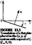
As a first example, let us investigate several simple motions and the corresponding derivation of the boundary conditions. Consider a flat plate at an angle of attack a moving at a constant velocity (4 in the negative X direction, as shown in Fig. 13.3. The translation of the origin is

V0=(*0, Y„,Z0) = (-t/., 0, 0)

and the rotation is

ft = 0

The vector n on the flat plate and in the body frame is

n = (sin a, 0, cos a)

Substituting these values into the boundary condition (Eq. (13.13a)) results in

/ ЭФ ЭФ

Подпись: FIGURE 13.3 Translation of a flat plate placed in the (x, y, z) system with a speed of (-{/„, 0, 0). Подпись: Yn Подпись: X

(УФ – V0 – ft X r) • n = I — + t4, 0, — I • (sin a, 0, cos ar) = 0

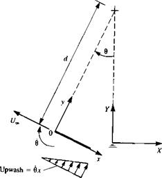
FIGURE 13.4

image557Motion of a flat plate along a circular arc with radius d.
and by assuming that a « 1 this reduces to the classical result
ЭФ / ЭФ

— =-U„ + —)ana~-U,*a (13.30)

For the second example, consider a one-degree-of-freedom motion of a flat plate along a circular arc (Fig. 13.4) with a radius of d. If the origin ( )0 is moving with a speed of U„, then

(X<>, Y0, Z„) = (-U,» cos в, 0, l/„ sin в)

But it is easy to observe that V0, at any moment, resolved in the direction of the (x, y, z) system will be

V0 = (-f4, 0, 0)

The rotation is

П = (0, в, 0)

image558

where

and

Я X r= (0z, 0, — вх)

Also, the normal is n = (0,0,1). The boundary condition for a flat plate (at
zero angle of attack in its coordinate system) is then

(УФ – Vo – Я x r) • n = – flz + IL, 0, — + вхJ • (0, 0, 1) = 0

which results in

ЗФ. x

– — „—u.. («.31,

Note that there is an upwash of w = вх due to this motion (see Fig. 13.4), resulting in lift (even though a = 0 in the flat plate’s coordinate system). Also, it is clear from this example that if the airfoil leading edge is placed at x = – c then instead of an upwash the airfoil will be subject to a downwash (or negative lift). Therefore, the location of the rotation axis is very important in motions with body rotations.

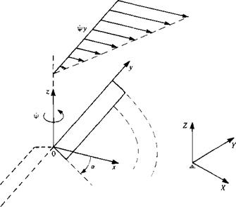
Next consider the rotation of a helicopter rotor in hover (Fig. 13.5) at a rate rj>. For this case,

V0 = (0,0,0)

Я = (0,0, V»)

Я X r = (-і/>у, 0)

n = (sin a, 0, cos or)

image559

FIGURE 13.5

Description of the motion of a helicopter rotor in hover.

The boundary condition for a flat plate rotor, at an angle of attack a, is

, /ЭФ ЭФ. ЭФ

(VO – V0 – Я X r) • n = (— + фу, ——– фх, —) • (sin a, 0, cos a) = 0

dx ay dz)

which results in

image560(13.32)

Note that to the rotor blade sections the oncoming velocity seems to increase with the radius |y|, and consequently most of the loads will be generated close to the tips.

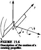
Подпись: For this case,Similarly, the boundary condition for a statically spinning propeller blade can be established by rotating the blades at a rate ф about the x axis as shown in Fig. 13.6 (observe the definition of a in Fig. 13.6 for this example).

V0 = (0,0,0) Я = (<*>, 0, 0)

Si X r = (0, — фг, фу) n = (sin a, 0, cos a)

and a is defined here in a similar manner to the wing at angle of attack. The boundary condition for a flat propeller blade is

/ЗФ ЭФ • ЭФ.

(VO — V0 – Я X r) • n = I ——, — + фг, —– фу)’ (sin a, 0, cos a) = 0

V dx ay dz J

which results in

image561(13.33)

Подпись:  FIGURE 13.6 Description of the motion of a rotating propeller.
image563

Again, most of the load will be generated at the tips where фу is the largest. Also, if the propeller advances at a speed of CL, parallel to its x axis,

Подпись: (13.34)
Подпись: ЭФ _ / ЭФ dz  dx
Подпись: /ЭФ  + U„J tan a + <j>y

then the boundary condition becomes

COMPUTATION OF PRESSURES

Solution of Eq. (13.12) will provide the velocity potential and the velocity components. Once the flow field is determined the resulting pressures can be computed by the Bernoulli equation. In the inertial frame of reference this equation is (note that [УФ]2 = УФ • УФ = [и2 + v2 + w2])

Подпись: (13.22)

(in X, Y, Z coordinates)

The magnitude of the velocity УФ is independent of the frame of reference (only the resolution of the velocity vector into its components is affected) and therefore the form of the first term in this equation remains unchanged. The

COMPUTATION OF PRESSURES Подпись: ЭФ - (V0 + ft X r) • УФ + — at Подпись: (13.23)
image555

time derivative of the velocity potential, however, is affected by the frame of reference and must be evaluated by using Eq. (13.11); therefore, the pressure difference p*. — p will have the form:131

(in x, y, z coordinates)

In the case of three-dimensional panel methods it is often simpler to use the instantaneous Bernoulli equation, in its original form (Eq. (2.35)):

Подпись: (13.24)Prct ~ P = Q2 vjt | ЗФ p 2 2 dt

Here Q and p are the local fluid velocity and pressure values and pref is the far-field reference pressure and uref is the magnitude of the kinematic velocity as given in Eq. (13.8):

vref= -[Vo + JlXr] (13.25)

It is often convenient to express this kinematic velocity in the direction of the moving x, y, z frame as [£/(t), V(t), W(f)], which can be obtained by a simple transformation fx (which is a function of the momentary rotation angles ф, в, rp, resembling Eq. (13.7o))

Подпись: (13.26)U j "ref,

v І =МФ, в, VO vrefy w) urefz

The total velocity at an arbitrary point on the body (or collocation point к in the case of a numerical solution) is the sum of the local kinematic velocity (e. g., the reference velocity in Eq. (13.25)) plus the perturbation velocity

Qa (Vref/> "ref,,,> "ref,)*: (ф» Яті Яп)к (13.27)

C — P Pref 1

‘*■’p 12

2P"ref

Подпись: О^^ЭФ Vref "ref dt Подпись: (13.28)

where (l, m, n)k are the local tangential and normal directions (see Fig. 9.10) and the components of vref in these directions are obtained by a transformation similar to Eq. (13.26). The local perturbation velocity is (q,, qm, qn) = (ЗФ/dl, ЭФ! Эт, дФ/дп) and of course the normal velocity component on the solid body is zero. The pressure coefficient can now be computed for each panel as

Подпись: P P ref p_ ipv%f COMPUTATION OF PRESSURES Подпись: (13.28л)

or if we use Eq. (13.23) then the pressure coefficient becomes:

Note that in situations such as the forward flight of a helicopter rotor uref can be selected as the forward flight speed or the local blade speed at each section on the rotor blade. Consequently different values of the pressure coefficient will be obtained—and this matter is usually left to be settled by the programmer. The contribution of an element with an area of ASk to the aerodynamic loads AF* is

AF* = – CPt(pv2ref)k AS* n* (13.29)

(Note that ure{ here has a subscript k, which means that it depends on the body coordinates. This is usually not recommended, but may be used in cases such as the forward flight of a helicopter rotor).

Once the potential field and the velocity field are obtained, the corresponding pressure field is calculated using Eq. (13.28a) and additional information such as forces, moments, surface velocity surveys, etc., can be obtained.

ADDITIONAL PHYSICAL CONSIDERATIONS

ADDITIONAL PHYSICAL CONSIDERATIONS
The above mathematical formulation, even after selecting a desirable com­bination of sources and doublets and after fulfilling the boundary conditions on the surface SB, is not unique. As we have seen in the previous chapters, for lifting flow conditions the magnitude of circulation depends on the wake shape and on the location of the wake shedding line and, therefore, an appropriate wake model needs to be established. Following the practice of the previous chapters, the wake model will be based on some additional physical conditions (e. g., the Kutta condition) as follows.

FIGURE 13.2

image554Possible assumption for wake shape near the trailing edge.

The validity of this assumption depends on the component of the kinematic velocity, normal to the trailing edge, which must be much smaller than the characteristic velocity (e. g., Qr) for Eq. (13.20) to be valid (see additional discussion of this condition in Section 13.11).

Also the Kelvin condition can be used to calculate the change in the wake circulation

f = 0 (.3,6)

Wake shape. Following the requirement of Section 9.3, that the wake is force-free, the Kutta-Joukowski theorem (Section 3.11) states that:

QXYw = 0 (13.21)

where Q is the total velocity. When the wake is modeled by a vortex distribution of strength Yw, Eq. (13.21) can be interpreted as a requirement that the velocity should be parallel to the circulation vector

Q II Yw (13.21a)

Also, in most cases the trailing edge has a finite angle and an additional assumption has to be made about the angle at which the wake leaves the trailing edge. In these cases it is usually sufficient to assume that the wake leaves the trailing edge at a median angle dT B J2, as shown in Fig. 13.2.