Category Aerodynamics for Engineering Students

Ground effects

In this section, the influence of solid boundaries on aeroplane (or model) perform­ance is estimated and once again the wing is replaced by the equivalent simplified horseshoe vortex.

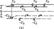
Since this is a linear problem, the method of superposition may be used in the following way. If (Fig. 5.17b) a point vortex is placed at height h above a horizontal plane, and an equal but opposite vortex is placed at depth h below the plane, the vertical velocity component induced at any point on the plane by one of the vortices is equal and opposite to that due to the other. Thus the net vertical velocity, induced at any point on the plane, is zero. This shows that the superimposition of the image vortex is equivalent in effect to the presence of a solid boundary. In exactly the same way, the effect of a solid boundary on the horseshoe vortex can be modelled by means of an image horseshoe vortex (Fig. 5.17a). In this case, the boundary is the level ground and its influence on an aircraft h above is the same as that of the ‘inverted’ aircraft flying ‘in formation’ h below the ground level (Figs 5.17a and 5.18).

Before working out a particular problem, it is clear from the figure that the image system reduces the downwash on the wing and hence the drag and power required, as well as materially changing the downwash angle at the tail and hence the overall pitching equilibrium of the aeroplane.

Example 5.2 An aeroplane of weight W and span Is is flying horizontally near the ground at altitude h and speed V. Estimate the reduction in drag due to ground effect. If W = 22 x 104N, h = 15.2m, s = 13.7m, V = 45m s-1, calculate the reduction in Newtons.

(U of L)

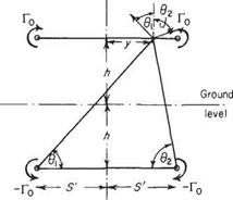
With the notation of Fig. 5.18 the change in downwash at у along the span is Aw f where

Aw t = -p-^-cos<?i – f – t——cos O2 4тггі 4лт2

On a strip of span 6y at у from the centre-line,

lift / = pVTo 6y

and change in vortex drag

* , /Aw A^= —

Подпись: (5.20)pVToSyAw

Ground effects

Fig. 5.18

Подпись: -AD, Подпись: 4-iv  r Подпись: d у

Total change in drag AD, across the span is the integral of Eqn (5.20) from —У to s’ (or twice that from 0 to s’). Therefore

Ground effects Подпись: 7Г2

With W = рКГо7Т5 i. e. and У = (7t/4)s (assuming elliptic distribution):

AD, = 1390N

A simpler approach is to assume that mid-span conditions are typical of the whole wing. With this the case

Подпись: 9 =92=9 = arc cos-У

/У2 + 4h2

and the change in drag is to be 1524N (a difference of about 10% from the first answer).

Influence of the downwash on the tailplane

On most aircraft the tailplane is between the trailing vortices springing from the mainplanes ahead and the flow around it is considerably influenced by these trails. Forces on aerofoils are proportional to the square of the velocity and the angle of incidence. Small velocity changes, therefore, have negligible effect unless they alter the incidence of the aerofoil, when they then have a significant effect on the force on the aerofoil.

Tailplanes work at incidences that are altered appreciably by the tilting of the relative wind due to the large downward induced velocity components. Each particu­lar aircraft configuration will have its own geometry. The solution of a particular problem will be given here to show the method.

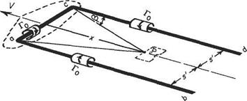
Example 5.1 Let the tailplane of an aeroplane be at distance x behind the wing centre of pressure and in the plane of the vortex trail (Fig. 5.16).

Assuming elliptic distribution, the semi-span of the bound vortex is given by Eqn (5.18) as

Fig. 5.16

The downwash at the mid-span point P of the tailplane caused by the wing is the sum of that caused by the bound vortex ac and that of each of the trailing vortices ab and cd. Using the special form of Biot-Savart equations (Section 5.2.2) the downwash at P:

wP J. = -^-2sin/3 ++cos/3)

4-їїх 4ns1

Подпись: + cos/3'_ Гр (sin /3 1

27Г X

From the sketch x = s’ cot /3 and s’ = (n/4)s

Подпись: Wp і =

Influence of the downwash on the tailplane

Г0 ( sin /3 l+cos/3

2тг cot /З

= ^(1 +sec/3)

7TZS

Now by using the Kutta-Zhukovsky theorem, Eqn (4.10) and downwash angle

8 CL
7Г3(AR)

Подпись: or Influence of the downwash on the tailplane

Wp

The derivative

дє _ де дСь _ дє да dCL да °l dCL

Подпись: дє да Influence of the downwash on the tailplane Подпись: (5.19)

Thus

For cases when the distribution is non-elliptic or the tailplane is above or below the wing centre of pressure, the arithmetic of the problem is altered from that above, which applies only to this restricted problem. Again the mid-span point is taken as representative of the whole tailplane.

Influence of the downwash on the tailplane

Ground


level


Influence of the downwash on the tailplaneInfluence of the downwash on the tailplane

Fig. 5.17

Formation flying effects

Aircraft flying in close proximity experience mutual interference effects and good estimates of these influences are obtained by replacing each aircraft in the formation by its equivalent simplified horseshoe vortex.

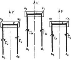
Consider the problem shown in Fig. 5.15 where three identical aircraft are flying in a vee formation at a forward speed V in the same horizontal plane. The total mutual interference is the sum of (i) that of the followers on the leader (1), (ii) that of the leader and follower (2) on (3), and (iii) that of leader and follower (3) on (2). (ii) and

(iii) are identical.

Formation flying effects

Fig. 5.15

components from the trailing vortices a2b2 and сзёз – The net result is an upwash on the leader.

(ii) These wings have additional influences to their own trails due to the leader and the other follower. Bound vortex aiCi and trailing vortices aibi, a2b2 produce downwashes. Again the net influence is an upwash.

From these simple considerations it appears that each aircraft is flying in a regime in which upward components are induced by the presence of the others. The upwash components reduce the downward velocities induced by the aircraft’s own trail and hence its trailing vortex drag. Because of the reduction in drag, less power is required to maintain the forward velocity and the well-known operational fact emerges that each aircraft of a formation has a better performance than when flying singly. In most problems it is usual to assume that the wings have an elliptic distribution, and that the influence calculated for mid-span position is typical of the whole wing span. Also any curvature of the trails is neglected and the special forms of the Biot-Savart law (Section 5.2.2) are used unreservedly.

The simplified horseshoe vortex

A simplified system may replace the complete vortex system of a wing when con­sidering the influence of the lifting system on distant points in the flow. Many such problems do exist and simple solutions, although not all exact, can be readily obtained using the suggested simplification. This necessitates replacing the wing by a single bound spanwise vortex of constant strength that is turned through 90° at each end to form the trailing vortices that extend effectively to infinity behind the wing. The general vortex system and its simplified equivalent must have two things in common:

(i) each must provide the same total lift

(ii) each must have the same value of circulation about the trailing vortices and hence the same circulation at mid-span.

These equalities provide for the complete definition of the simplified system.

The simplified horseshoe vortex Подпись: T Го

The spanwise distributions created for the general vortex system and its simplified equivalent are shown in Fig. 5.14. Both have the same mid-span circulation Го that is now constant along part of the span of the simplified equivalent case. For equivalence in area under the curve, which is proportional to the total lift, the span length of the single vortex must be less than that of the wing.

Thus


Го2/ = area under general distribution = ^

pV

Hence


Подпись: (5.16)s’ total lift s 2spVTo

2У is the distance between the trailing vortex core centres. From Eqn (5.47a) (see page 246) it follows that

L = pV[24] [25]s2‘2ivA

and substituting also

Подпись: 7ГГо = 4sVEA„ sin и

У рУ^^тгАї s 2pV24sP-Y^A„ sin и I

7Г A 4 [Ai-A3 + A5-A7…}

Подпись: s _ 4 s' TV Подпись: і M AT AI A Подпись: (5.17)

For the general case then:

For the simpler elliptic distribution (see Section 5.5.3 below):

A3 = А3 = Ат = 0

(5.18)

In the absence of other information it is usual to assume that the separation of the trailing vortices is given by the elliptic case.

Variation of velocity in vortex flow

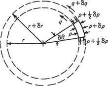
To confirm how the velocity outside a vortex core varies with distance from the centre consider an element in a thin shell of air (Fig. 5.12). Here, flow conditions depend only on the distance from the centre and are constant all round the vortex at any given radius. The small element, which subtends the angle 86 at the centre, is

Variation of velocity in vortex flow

Fig. 5.12 Motion of an element outside a vortex core circulating round the centre in steady motion under the influence of the force due to the radial pressure gradient.

Considering unit axial length, the inwards force due to the pressures is:

(p + 8p)(r + 6r)6Q-pr6Q – 2{p –]^8p)8r^86

which reduces to 8p(r — ^ 6r)66. Ignoring f Sr in comparison with r, this becomes r 8p 86. The volume of umt length of the element is r 8r 86 and therefore its mass is pr8r86. Its centripetal acceleration is (velocity)2/radius, and the force required to produce this acceleration is:

mass(ve!5dty£= rW

radius r

Equating this to the force produced by the pressure gradient leads to

r6p = pq26r since 66 Ф 0 (5.13)

Now, since the flow outside the vortex core is assumed to be inviscid, Bernoulli’s equation for incompressible flow can be used to give, in this case,

P + p<? = {p + 6p)+ іp(q + 6qf

Expanding the term in q + 8q, ignoring terms such as (6q)2 as small, and cancelling, leads to:

6p + pq 8q = 0 i. e.

6p = —pq6q (5-14)

Substituting this value for 6p in Eqn (5.13) gives

pq2 8r + pqrSq = 0 which when divided by pq becomes

q 8r + r 8q = 0

But the left-hand side of this equation is 6(qr). Thus

8{qr) = 0

qr = constant (5.15)

This shows that, in the inviscid flow round a vortex core, the velocity is inversely proportional to the radius (see also Section 3.3.2).

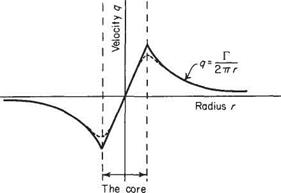
When the core is small, or assumed concentrated on a line axis, it is apparent from Eqn (5.15) that when r is small q can be very large. However, within the core the air behaves as though it were a solid cylinder and rotates at a uniform angular velocity. Figure 5.13 shows the variation of velocity with radius for a typical vortex.

The solid line represents the idealized case, but in reality the boundary is not so distinct, and the velocity peak is rounded off, after the style of the dotted lines.

Variation of velocity in vortex flow

Variation of velocity in vortex flow

Fig. 5.13 Velocity distribution in a real vortex with a core


Special cases of the BiotSavart law

Equation (5.6) needs further treatment before it yields working equations. This treatment, of integration, varies with the length and shape of the finite vortex being studied. The vortices of immediate interest are all assumed to be straight lines, so no shape complexity arises. They will vary only in their overall length.

Подпись: 8v ■ Special cases of the BiotSavart law Подпись: (5.8)

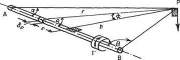
A linear vortex of finite length AB Figure 5.10 shows a length AB of vortex with an adjacent point P located by the angular displacements a and /? from A and В respectively. Point P has, further, coordinates r and 6 with respect to any elemental length 8s of the length AB that may be defined as a distance s from the foot of the perpendicular h. From Eqn (5.7) the velocity at P induced by the elemental length 8s is

Special cases of the BiotSavart law

in the sense shown, i. e. normal to the plane APB.

To find the velocity at P due to the length AB the sum of induced velocities due to all such elements is required. Before integrating, however, all the variables must be quoted in terms of a single variable. A convenient variable is ф (see Fig. 5.10) and the limits of the integration are

<74 =-(I-a) to <6B = +(|-/?)

since ф passes through zero when integrating from A to B.

sin в = cos ф, r2 = h2 sec2 ф dr = d(h tan ф) = h sec2 фд. ф

The integration of Eqn (5.8) is thus

,+(*/2-/3) Г Г Г. /7Г N. /7Г ]

= —-гсозфаф = —— sin — р + sin — а

J-M2-а) 4тгй v y 4тгА L V2 и) 2 )

р+(тг/2-/3) p -(*/2-a)

Подпись: (5.9)Г, „

– —— (cos а + cos в) 4тгп ‘

This result is of the utmost importance in what follows and is so often required that it is best committed to memory. All the values for induced velocity now to be used in this chapter are derived from this Eqn (5.9), that is limited to a straight line vortex of length AB.

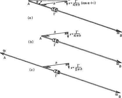
The influence of a semi-infinite vortex (Fig. 5.11a) If one end of the vortex stretches to infinity, e. g. end B, then /3 = 0 and cos /3 = 1, so that Eqn (5.9) becomes

Подпись: (5.10)Г,

v = —* (cos a + 1) 47ГЙ

Special cases of the BiotSavart law Подпись: (5.11)

When the point P is opposite the end of the vortex (Fig. 5.11b), so that a = 7t/2, cos a = 0, Eqn (5.9) becomes

The influence of an infinite vortex (Fig. 5.11c) When a = /3 = 0, Eqn (5.9) gives

Подпись: (5.12)Г

Подпись: v =2nh

and this will be recognized as the familiar expression for velocity due to the line vortex of Section 3.3.2. Note that this is twice the velocity induced by a semi-infinite vortex, a result that can be seen intuitively.

In nature, a vortex is a core of fluid rotating as though it were solid, and around which air flows in concentric circles. The vorticity associated with the vortex is confined to its core, so although an element of outside air is flowing in circles the element itself does not rotate. This is not easy to visualize, but a good analogy is with a car on a fairground big wheel. Although the car circulates round the axis of the wheel, the car does not rotate about its own axis. The top of the car is always at the top and the passengers are never upside down. The elements of air in the flow outside a vortex core behave in a very similar way.

P

Special cases of the BiotSavart law

Fig. 5.11

The Biot-Savart law

The original application of this law was in electromagnetism, where it relates the intensity of the magnetic field in the vicinity of a conductor carrying an electric current to the magnitude of the current. In the present application velocity and vortex strength (circulation) are analogous to the magnetic field strength and electric current respectively, and a vortex filament replaces the electrical conductor. Thus the Biot-Savart law can also be interpreted as the relationship between the velocity induced by a vortex tube and the strength (circulation) of the vortex tube. Only the fluid motion aspects will be further pursued here, except to remark that the term induced velocity, used to describe the velocity generated at a distance by the vortex tube, was borrowed from electromagnetism.

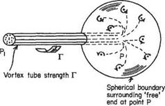
Allow a vortex tube of strength Г, consisting of an infinite number of vortex filaments, to terminate in some point P. The total strength of the vortex filaments will be spread over the surface of a spherical boundary of radius R (Fig. 5.7) as the filaments diverge from the point P in all directions. The vorticity in the spherical surface will thus have the total strength Г.

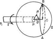
Owing to symmetry the velocity of flow in the surface of the sphere will be tangential to the circular line of intersection of the sphere with a plane normal to the axis of the vortex. Moreover, the direction wifi be in the sense of the circulation about the vortex. Figure 5.8 shows such a circle ABC of radius r subtending a conical angle of 29 at P. If the velocity on the sphere at R, 9 from P is v, then the circulation round the circuit ABC is Г’ where

r/ = 27ri? sin0v (5.1)

The Biot-Savart law

Fig. 5.8

Putting r = radius of circuit = R sin 0, Eqn (5.1) becomes

Г’ = 2ttrv (5.2)

Now the circulation round the circuit is equal to the strength of the vorticity in the contained area. This is on the cap ABCD of the sphere. Since the distribution of the vorticity is constant over the surface

p, _ surface area of cap ^ _ 2тгі?2(1 — cos 0) surface area of sphere 4тгR2

Подпись:Equating (5.2) and (5.3) gives

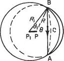
Now let the length, PP, of the vortex decrease until it is very short (Fig. 5.9). The circle ABC is now influenced by the opposite end P. Working through Eqns (5.1),

(5.2) and (5.3) shows that the induced velocity due to Pi is now

Подпись: (5.5)

The Biot-Savart law

Vl = 4^(1_ cosffl)

The Biot-Savart law

since r = Ri sin 0i and the sign of the vorticity is reversed on the sphere of radius R as the vortex elements are now entering the sphere to congregate on Pi.

The net velocity in the circuit ABC is the sum of Eqns (5.4) and (5.5):

Г

V — Vi = ——————— [1 — COS 6 — (1 – COS#])]

47Г r

— (cos 6 — cos 6)

47ГГ

As Pi approaches P

cos 6 —► cos(0 — 86) = cos 6 + sin 6 86

and

Подпись: 8vV — Vi

giving

Подпись: (5.6)8v = -—sn686
47ГГ

The Biot-Savart law Подпись: (5.7)

This is the induced velocity at a point in the field of an elementary length 8s of vortex of strength Г that subtends an angle 86 at P located by the coordinates R, 6 from the element. Since r = і? sin# and R86 = fosin# it is more usefully quoted as:

Helmholtz’s theorems

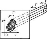
The four fundamental theorems of vortex motion in an inviscid flow are named after their author, Helmholtz. The first theorem has been discussed in part in Sections 2.7 and 4.1, and refers to a fluid particle in general motion possessing all or some of the following: linear velocity, vorticity, and distortion. The second theorem demon­strates the constancy of strength of a vortex along its length. This is sometimes referred to as the equation of vortex continuity. It is not difficult to prove that the strength of a vortex cannot grow or diminish along its axis or length. The strength of a vortex is the magnitude of the circulation around it and this is equal to the product of the vorticity Є and area S. Thus

T = CS

It follows from the second theorem that (S is constant along the vortex tube (or filament), so that if the section area diminishes, the vorticity increases and vice versa. Since infinite vorticity is unacceptable the cross-sectional area S cannot diminish to zero.

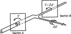
In other words a vortex line cannot end in the fluid. In practice the vortex line must form a closed loop, or originate (or terminate) in a discontinuity in the fluid such as a solid body or a surface of separation. A refinement of this is that a vortex tube cannot change in strength between two sections unless vortex filaments of equivalent strength join or leave the vortex tube (Fig. 5.6). This is of great importance in the vortex theory of lift.

The third and fourth theorems demonstrate respectively that a vortex tube consists of the same particles of fluid, i. e. there is no fluid interchange between tube and surrounding fluid, and the strength of a vortex remains constant as the vortex moves through the fluid.

The theorem of most consequence to the present chapter is theorem two, although the third and fourth are tacitly accepted as the development proceeds.

Helmholtz&#39;s theorems

Fig. 5.6

Laws of vortex motion

The theoretical modelling of the flow around wings was discussed in the previous section. There the use of an equivalent vortex system to model the lifting effects of a wing was described. In order to use this theoretical model to obtain quantitative predictions of the aerodynamic characteristics of a wing it is necessary first to study the laws of vortex motion. These laws also act as a guide for understanding how modern computationally based wing theories may be developed.

In the analysis of the point vortex (Chapter 3) it was considered to be a string of rotating particles surrounded by fluid at large moving irrotationally under the influence of the rotating particles. Further, the flow investigation was confined to a plane section normal to the length or axis of the vortex. A more general definition is that a vortex is a flow system in which a finite area in a normal section plane contains vorticity. Figure 5.5 shows the section area S of a vortex so called because S possesses vorticity. The axis of the vortex (or of the vorticity, or spin) is clearly always normal

Laws of vortex motion

Fig. 5.5 The vorticity of a section of vortex tube

to the two-dimensional flow plane considered previously and the influence of the so-called line vortex is the influence, in a section plane, of an infinitely long, straight-line vortex of vanishingly small area.

In general, the vortex axis will be a curve in space and area S will have finite size. It is convenient to assume that S is made up of several elemental areas or, alternatively, that the vortex consists of a bundle of elemental vortex lines or filaments. Such a bundle is often called a vortex tube (c. f. a stream tube which is a bundle of streamlines), being a tube bounded by vortex filaments.

Since the vortex axis is a curve winding about within the fluid, capable of flexure and motion as a whole, the estimation of its influence on the fluid at large is some­what complex and beyond the present intentions. All the vortices of significance to the present theory are fixed relative to some axes in the system or free to move in a very controlled fashion and can be assumed to be linear. Nonetheless, the vortices will not all be of infinite length and therefore some three-dimensional or end influ­ence must be accounted for.

Vortices conform to certain laws of motion. A rigorous treatment of these is precluded from a text of this standard but may be acquired with additional study of the basic references.[23]

The horseshoe vortex

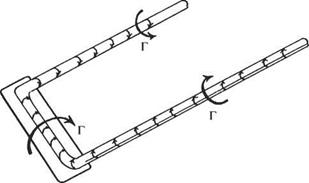
The total vortex system associated with a wing, plus its replacement bound vortex system, forms a complete vortex ring that satisfies all physical laws (see Section 5.2.1). The starting vortex, however, is soon left behind and the trailing pair stretches effectively to infinity as steady flight proceeds. For practical purposes the system consists of the bound vortices and the trailing vortex on either side close to the wing. This three-sided vortex has been called the horseshoe vortex (Fig. 5.3).

The horseshoe vortex

Fig. 5.4 The simplified horseshoe vortex

Study of the completely equivalent vortex system is largely confined to investigat­ing wing effects in close proximity to the wing. For estimation of distant phenomena the system is simplified to a single bound vortex and trailing pair, known as the simplified horseshoe vortex (Fig. 5.4). This is dealt with in Section 5.3, before the more involved and complete theoretical treatments of wing aerodynamics.