Category Aerodynamics of V/STOL Flight

Hovering Performance

The helicopter rotor in hover or in vertical climb is relatively easy to analyze in comparison with its other states of operation. Neither the blade forces nor the blade pitch varies with azimuth position. In addition, a trailing vortex pattern is established underneath the rotor, which makes possible the application of propeller vortex theory.

The principles developed in Chapter 4 can be applied directly to the heli­copter in hover. Hence from Eq. (4-10) the ideal power required by a hovering rotor would be

Pt = Tw

Подпись:J3/2

~ у/Щ’

Подпись: Cj Подпись: T pAV Подпись: (5-2)

In conformity with past practice, thrust and power coefficients for a helicopter rotor are defined by

Подпись:(5-3)

Подпись: CP, Подпись: P pAVj Подпись: (5-4)

In terms of these coefficients, the thrust and ideal power are related by

The power, according to Eq. (5-1) or (5-4), is the least possible power with which the thrust of the rotor can be attained. This ideal power is low for two reasons. First, the momentum theory ignores any profile drag of the blades and, second, the actuator-disk concept is optimistic because of the tip losses incurred by a physical rotor with a finite number of blades.

A hovering rotor certainly performs a useful function, but, regardless, it accomplishes no useful work, so that its efficiency is always zero. Therefore the performance of hovering rotors is sometimes evaluated on the basis of the figure of merit M. This parameter is defined as

Подпись: M =Pi

P’ where Pi = ideal power according to Eq. (5-1),

P — actual total power required by the rotor.

Подпись: M = Hovering Performance Hovering Performance Подпись: (5-5)

If P is written as Pt + AP, then M can be written as

ACP, for a given rotor, does not depend appreciably on the thrust co­efficient. Thus the figure of merit of a given rotor will approach unity as the thrust coefficient increases, provided the rotor does not stall or encounter compressibility. Therefore it is important when comparing two different rotors by use of the figure of merit to compare them at equal thrust co­efficients ; otherwise the comparison can be misleading.

Consider a family of rotors, all of which produce the same thrust and have the same tip speed and solidity. Solidity, as defined in Chapter 4, is the ratio of total blade area to disk area and for a rectangular blade is equal to

В being the number of blades and c, the constant chord. As the radius of the rotor is increased, the induced power for the constant thrust will de­crease. However, the profile power will increase with increasing radius. Thus there will be some optimum radius for which the required power will be a minimum. This radius can be found approximately as shown in Ref. 2 by assuming that the profile drag coefficient Cd is a constant. For a rectangular blade the total power in hover is given approximately by

Подпись: y/2npRp _ T312 , P°Cd0V3rnR2

– t + C>R1-

Подпись: C, R2 Подпись:To find the optimum R, dP/dR is equated to zero. dP

M

or, multiplying by R,

Подпись:= 2 C2R2.

Thus for the optimum radius the induced power is equal to twice the profile power, and the figure of merit for the optimum physical rotor (which must have some profile drag) is

M = f.

The foregoing analysis is possibly not too realistic. In defining the optimum rotor for a given application, we must consider other restrictions such as structural and controllability requirements. The root stresses on a blade of uniform cross section result primarily from the centrifugal forces. Since these forces vary directly with the cross-sectional area of the blade, the root stresses depend primarily on the rotor tip speed and do not vary with the chord (assuming that the thickness-to-chord ratio is a constant). For controllability we usually specify an average lift coefficient for the rotor. Because, approximately,

T = В J ±p(cor)2cC, dr,

Hovering Performance

if C, and c are assumed constant, an average С, = C, can be calculated as

Thus, in comparing one rotor with another for a given application, we should probably hold CL constant, which means that a will vary in accord­ance with the above.

In terms of CL, the total power can be written

p _ T3/2 3TVT cd

Hence for the same CL the profile power is not a function of radius. From the above, from a purely aerodynamic standpoint, the best rotor is one with large radius and low tip speed. Practically, other considerations that must be taken into account include transmission weight as the tip speed is reduced and blade weight and blade clearance problems as the blade radius

increases.

It is very enlightening to express the figure of merit in terms of CL.

Hovering Performance

or

Hovering Performance

Thus the figure of merit depends on the section drag-to-lift ratio and on the ratio of tip velocity to the downwash velocity.

To allow a margin below the stall, most rotors are designed for a CL of approximately 0.5. At this value of CL the drag-lift ratio is approximately

0. 021. Typical values of the ratio of tip velocity to downwash velocity range from approximately 17 to 23. Hence a typical figure of merit would be approximately 0.76.

In several respects the figure of merit is useless. As an academic exercise, it is interesting, but in a practical application we must consider the power; for example, for a constant T, VT, and CL, increasing the disk loading improves the figure of merit but increases the total power.

The fact that one rotor has a higher figure of merit than another is not sufficient to indicate its relative superiority but might mean simply that the first rotor is acting at a higher thrust coefficient so that its induced power is high.

Aerodynamics of the helicopter

The purpose of this chapter is to establish methods of determining the various aerodynamic rotor forces required in the design and analysis of the helicopter. These methods are presented for all operating states of the rotor, such as hovering, powered vertical ascent and descent, forward flight, and autorotation. Initially, we consider the isolated-single rotor, and then follow with its application to different helicopter configurations.

Before we examine the aerodynamic forces to which it is subjected, we describe a typical helicopter rotor. In forward flight a rotor blade encounters

Aerodynamics of the helicopter

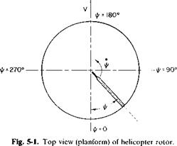
an unsteady flow, due to the forward velocity, which adds to the rotational velocity of the blade as it advances into the direction of flight and then subtracts from the rotational velocity as it retreats. This is illustrated in Fig. 5-1, which is a planform view of one blade of a rotor. Its azimuth position, denoted by ij/, is measured positively in the direction of its rotation from its downstream position.

At the tip of the blade the velocity of the air in relation to the blade is equal to (toR + V) at ф = 90° and (coR —V)aUl/ = 270°. Unless some pro­vision were made, these unequal velocities would produce unequal lifts on either side of the helicopter and would result in an undesirable rolling move­ment and excessive alternating air loads on the blade. It was Juan de la Cierva who, in the early 1920’s, first applied the principle of an articulated rotor to the autogyro as a means of equalizing the lift of the advancing and retreating blade. In an articulated rotor the blade is allowed to flap up and down about a horizontal hinge close to the center of rotation of the rotor. Thus, as the blade advances and develops more lift, it begins to flap upward. This then introduces a downward vertical component of velocity in relation to the blade which reduces its angle of attack, hence the lift of the advancing blade. As it retreats, the opposite is true, for a downward flapping of the blade produces an increased lift.

In addition to being able to flap, the blade is also frequently hinged about a vertical axis near the center of rotation so that it is free to oscillate or “lead and lag” in the plane of rotation. Such a rotor is described as being fully articulated when it employs this universal action. The lead and lag motion of the blade is provided to relieve the chordwise bending moments which result from the unsteady coriolis forces produced by the flapping.

The teetering or seesaw type of rotor is another design often used for helicopters. The principle is similar to the flapping rotor except that the blades are connected rigidly to one another, and as the advancing blade flaps up the opposite, or retreating, blade must flap down.

Because the blade of the articulated rotor is free to flap, there is an up­ward movement of its sections about the flapping axis which is caused by the thrust that occurs even in steady hovering. In this case the blade assumes a position in which the moments about the flapping hinge due to the centri­fugal force and weight of the blade exactly balance those produced by thrust. This steady deflected position of the blade from a horizontal plane is referred to as coning, whereas its oscillating movement to both sides of the steady position is called flapping.

A study of the dynamics of blade motion will show that the flapping motion lags the disturbing aerodynamic forces by 90°. Thus, because of the unbalance in the resultant velocities on the advancing and retreating sections, the blade reaches its maximum flapping angle at ф = 180° and its minimum at ф = 0°. This longitudinal flapping, fore and aft, is the result of unequal velocities between the advancing and retreating sections.

In addition to longitudinal flapping, an articulated rotor also experiences lateral flapping, which is the result of the coning that produces higher angles of attack on the blades at ф = 180° than at ф = 0°. This is best explained by reference to Fig. 5-2. It is readily seen that if /? equals the coning angle a component of the forward velocity V sin /? is going up through the blade at ф = 180°, thereby increasing the angle of attack of the blade sections at this position. However, at ф = 0° a component of equal magnitude but opposite direction is acting on the blade to decrease its angle of attack. Thus the blade has its maximum lateral flapping at ф = 270° and its minimum at іA = 90°.

The motion of lateral and longitudinal flapping caused by coning and unequal velocities is referred to as aerodynamic flapping. Thus, if no control motion is added to the blade, a blade that rotates counterclockwise, as viewed from above, would flap up in the front and on the left side (looking forward) and down in the rear and on the right side.

In order to counteract aerodynamic flapping and to direct the thrust vector of the rotor as desired, it is necessary to provide some means of controlling the angle of attack of the blade sections in their movement around the azimuth. This can be accomplished in several ways. In one method the shaft of the rotor is tilted. Suppose the shaft of a hovering

Aerodynamics of the helicopter

articulated rotor were suddenly tilted. Because the blade is free to flap, its angular momentum would tend to keep it in a plane perpendicular to the original shaft position. However, as it rotated in this plane about the tilted shaft, the cyclical angle of attack of the blade would produce flapping relative to the shaft until the plane of the blade was once again perpendicular to the shaft. Because the blade is coned, it would have been more precise to speak of the plane defined by the path of the tips of the blade sections. Thus it is seen that this plane called the tip-path plane, tends to be perpendicular to the shaft.

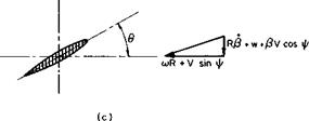
A more common method of controlling the direction of the tip-path plane is by the use of cyclic pitch. The blade pitch angle is the angle between the plane perpendicular to the rotor shaft and the chord line of a reference station on the blade. This angle, shown in Fig. 5-3c as в, is controlled by means of a swashplate mechanism as the blade moves around the azimuth. The cyclical pitch variation introduces additional blade flapping to counter­act the aerodynamic flapping and to direct the thrust vector for forward propulsion or control.

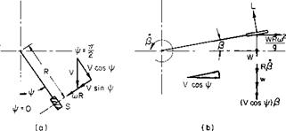
The equations describing the dynamic behavior of a helicopter rotor blade are lengthy and are not given here. Instead, a relatively simple example will illustrate the essential features of the problem’s solution. Instead of a con­tinuous rotor, consider a finite wing rotating on the end of a long “weightless, zero-thickness” rod, as shown in Fig. 5-3. The rod is long in comparison with the span of the wing so that the velocity over the wing can be assumed to be constant with respect to radius. At an azimuth position

Aerodynamics of the helicopter

Aerodynamics of the helicopter

Fig. 5-3. An articulated blade: (a) planform view; (b) vertical plane containing support rod; (c) view looking in along rod.

of ф the velocity normal to the wing is (coR + V sin ф). The component in the plane of rotation parallel to the wing span is V cos ф.

Figure 5-3b is a view in a vertical plane containing the support rod and wing. The wing is flapping up at the rate P and is instantaneously at an angle of p. At this instant the wing produces a lift L. If the weight of the wing is W, a centrifugal force, WRa)2/g will exist.

The velocities experienced by the wing are shown in Fig. 5-3b. Because of the angular velocity /?, a downward velocity of Rfi exists. Also a down­ward component normal to the wing equal to (V cos ф)Р exists as a result of the component of the free-stream velocity parallel to the wing.

If, relative to the plane of rotation, the wing is pitched at an angle of 9, its angle of attack will be

_ (PV cos ф + RP + w) coR + V sin ф

An assumption that the resultant velocity is approximately 10R + V sin ф leads to the following for the lift:

L = ^paS[(ajR + V sin ф)2в — (coR + V sin ф)(УР cos ф + RP + w’)],

Aerodynamics of the helicopter

where a is the slope of the wing lift curve and S is the wing area; p, the time rate of change of /?, can be written as

where со = ф. Hence the expression for the lift becomes

— = (1 + p sin ф)2в – (1 + p sin ф)(рР COS Ф + a аф vT)

where

L _ V

L _ $pS(coR)2’ ^ ~ aoR

If the rod is pinned so that the wing is free to flap, the sum of the moments about the hinge will produce an angular acceleration of the wing given by

W

£m = jR2p,

where W is the weight of the wing.

Подпись: d2P сіф2 Подпись: gRSpa 2W Aerodynamics of the helicopter
Aerodynamics of the helicopter Aerodynamics of the helicopter

From Fig. 5-3c and the preceding relationships this equation can be written as

Подпись: — P —g

co2R

We now assume that P and в have the form

P = po — a,, cos ф — sin ф — a2 cos 2ф — — в = 90 + в j cos ф + 92 sin ф.

We recall that

sin2 ф = j — j cos 2i//, cos2 Ф – j + і cos 2ф, sin ф cos ф = j sin 2ф,

and retain only constant or first harmonic terms; the differential equation in P then becomes

Po = + y)^° + 0icos^ + еійпф) + 2/i0o sin 11/ + цв2

U? Q* vv W "I <r

+ iip0cosil/ + —sin^ + ЬіСОьф — aisinij/ — — — sin^

2 Tj* rj* J w /

Подпись: g co2R w For the above to be satisfied for all ф it follows that 1 + М2/2 a, 2ц и

Подпись: 1 - n2/2 2 1 - fi2/2 0 1 - n2/2 VT

Aerodynamics of the helicopter

Ol — 02 + —————- ^~7Z 0n

This simple configuration illustrates two important results of more elaborate analyses. First, notice that the displacement of the blade lags the control displacement by 90°. An increase in в1 produces a decrease in bt and an increase in 02 produces an increase in av Second, notice that, in forward flight (ц ф 0), 0O produces longitudinal flapping, whereas p0 pro­duces lateral flapping.

Variation of Induced Velocity with Axial Distance

Variation of Induced Velocity with Axial Distance Variation of Induced Velocity with Axial Distance

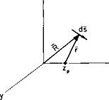
In subsequent material the variation of the induced velocity with axial distance from the propeller disk plane is needed. This variation can be

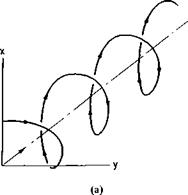
Fig. 4-13. Geometry of a helical vortex.

found approximately by calculating the axial velocity induced along the axis of a semi-infinite helical vortex filament by using the Biot-Savart law. A vortex helix is shown in Fig. 4-13a and a segment of the helix in Fig. 4-13fi.

If p is the pitch of the helix, the equation of the helix in terms of the generating angle 0 is

x = R cos 0,

у — R sin

Подпись: (4-53)7 = P± 2n

If R is the radius vector from the origin to a differential element of the vortex, then for a point zp along the z-axis the radius vector r from zp to a differential element ds is

r = R – kzp

or

r = іR cos 0 + jR sin 0 +

The differential element of the vortex is simply dR, where

Подпись: ?! 2n R = iR cos 0 + R sin 0 + к

so that

ds = ( — iR sin 0 + jR cos 0 + 1 ) dO.

Variation of Induced Velocity with Axial Distance Подпись: dO.

Thus

Подпись: 2P Подпись: 1 + Подпись: /R2 + zl

This integrates to

Finally in terms of the velocity induced at the propeller disk (zp = 0), the axially induced velocity becomes

Подпись:wa(0) Уі + (z/R)2

Observe that for (z/R) = — oo, (4-54) is equal to zero, whereas for (z/R) = + oo the velocity ratio is equal to 2 in agreement with the results of momentum theory.

Static Performance

Подпись:
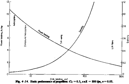
In almost any paper on the design analyses of VTOL aircraft in which different configurations are compared a graph reflecting the static perform-

ance of propellers can be found. This graph usually takes the form of static thrust capability (lb/hp) versus disk loading (lb/sq ft). Not to be outdone, this book includes such a graph (see Fig. 4-14), which was prepared in the following manner.

First, from experience it is known that the induced power is approximately 15% higher than that predicted by momentum theory. Second, it is assumed

Variation of Induced Velocity with Axial Distance

that the chord and Cd are independent of radius and that a, is small so that VR ~ cor. Hence, approximately,


550 hp = 1.15 + BPcC^mR)3R

s/2 pA 8


(4-55)


By rewriting Cd in terms of the lift-drag ratio є and an average C, and dividing by T we obtain


hp = 1.15 s/TjA BCpeCL(ooR)3R T 550 s/^F (8)550Г


but


L Bpcco2R3 Be

a ———

nR


and


Hence


hp _ U5 JtJa 3coRe

T 550 ^2F 4(550)


(4-56)


and


(4.57)

A 6

Figure 4-14 was prepared for standard sea-level conditions for an average CL of 0.5 and a tip speed of 800 fps. The solidity required to maintain these conditions is also illustrated. An e of 0.03 was assumed for the calculations. Also shown in the figure are the ranges in which various types of aircraft normally operate.

Further considerations on the static performance of helicopter rotors are undertaken in Chapter 5.


Problems

1. An aircraft has an equivalent flat-plate area of 2 sq ft, an elliptic wing of aspect ratio 6 with an area of 160 sq ft, and a gross weight of 2000 lb. Its engine develops 150 shaft horsepower at 2500 rpm. At SSL conditions,


and equipped with a 6 ft-diameter propeller with the characteristics of Fig. 4-11, what will be its maximum speed?

2. What would Fmax be for the aircraft of Problem 1 equipped with an ideal propeller with no profile drag?

3. Given the propeller in Fig. 4-12, estimate the section C, for a J of 1.0 at r = 3R/4. Note that /1 is the pitch angle of the chord line.

4. Estimate the initial acceleration of the aircraft in Problem 1 on takeoff.

5. A 10-bladed special-purpose propeller has a constant 10-in. chord and a 12% thick airfoil section and is designed to operate at an advance ratio of 1.5. Calculate the correction to the section angle of attack at a radius of 20 in. The propeller has a diameter of 6 ft.

Propeller Charts and Empirical Methods

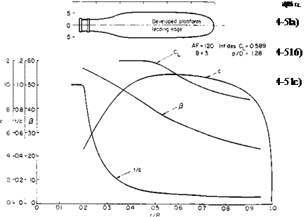
A large majority of propeller analyses, designs, and selections are based on empiricism. Propeller designs are identified by their geometry: in partic­ular, by the number of blades, integrated design lift coefficient, blade activity factor, and pitch-diameter ratio.

Propeller Charts and Empirical Methods Подпись: (4-47)

The integrated design lift coefficient is obtained from

and represents the average of the design section C,’s weighted by the radius squared.

The blade activity factor is defined by

Propeller Charts and Empirical Methods(4-48)

The blade activity factor is simply another measure of the solidity. In a constant chord blade the solidity and activity factor are related by

128B(AF)

100,000л

Propeller Charts and Empirical Methods

Aircraft propellers have activity factors of approximately 100 to 150. It is often stated that the activity factor is a measure of a blade’s capacity to absorb power.

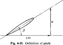
The pitch of a propeller blade is the distance it would advance in one revolution if there were no slip. Hence in Fig. 4-10 the pitch p is given by

p = 2nr tan /?.

For a constant pitch propeller the section pitch angles are calculated from

ft = tan -1 (4-49)

roc

where p/D is the pitch-diameter ratio.

Propeller Charts and Empirical Methods

Подпись: J J and X are related by Propeller Charts and Empirical Methods Подпись: (4-50)

Standardized propeller data, that is, thrust and power coefficients and efficiency, are usually presented as a function of the propeller advance ratio J defined by

Thrust, power, and torque coefficients for propellers are usually defined in terms of the product nD (for a characteristic velocity) and D2 (for reference

area).

Propeller Charts and Empirical Methods

Hence

Because the symbols CT, CQ, and C,. throughout the literature define the thrust, torque, and power coefficients in different ways, we must be careful in the use of any graphs that present these quantities.

In terms of CT, CP, and J, the efficiency is

Подпись: (4-52)JCT

Cp

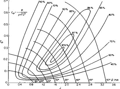
One method of presenting propeller data is given in Fig. 4-11, reproduced from Ref. 7. This is a map of CP versus J with contours of constant t] and P drawn. The values of P are for the 0.75R station. The geometry of this particular propeller is given in Fig. 4-12. A method for correcting data such as these to other propellers of similar geometry but different numbers of blades or activity factors is presented in Ref. 7.

In Fig. 4-11 it is seen that a propeller can be a very efficient device. For this particular propeller there is a large area of operating conditions for which the efficiency is better than 85%.

Design of a New Propeller

Until now the combined momentum-blade element theory and vortex theory have been developed more from the standpoint of analyzing a given propeller than from the standpoint of designing a new one. We now present the procedure for designing a propeller for a desired purpose.

For a free-stream propeller, that is, one for which the inflow is uniform, the optimum propeller satisfies the Betz condition, as proved in Ref. 5, which states that the trailing vortex sheet moves aft as a rigid helical sheet. In terms of the blade element velocity diagram, this means that from Fig. 4-5 the following must hold:

Подпись: (4-43)cor tan (ф – I – a,) = constant.

If H’o is defined as

Design of a New Propellerw0 = cor tan (ф + a,) — V, af = tan-1

Design of a New Propeller Подпись: (4-46)
Подпись: T = Bp
Подпись: (4-45 a)
Подпись: (4-45 b)

or in dimensionless form

Then, either from Mach number, stalling, control margin, or optimum l/d considerations, a radial distribution of C, is selected, which leads to the values of a along the blade and, if a thickness ratio is chosen, to the distribu­tion of e. With £, new values of T and Q can be calculated to include the profile drag losses and w0 adjusted accordingly.

Blade sections can now be selected to produce the desired C, values. For a propeller with a high tip speed, in which compressibility might be a problem, high-speed airfoil sections operating at the design lift coefficient, hence producing flat pressure distributions, would be selected. For marine propellers the same procedure is followed to avoid the onset of cavitation.

Again, in laying out the sections, their cambers and angles of attack should be corrected for wide-blade and thickness effects, as previously discussed.

Most propellers for V/STOL operation will, of course, be variable pitch. This means that they will be designed for some condition; for example, static performance. One will then simply “live” with whatever performance they possess at off-design conditions. It is usually better for VTOL operation to design the propeller for static thrust conditions and to accept the efficiency in cruise that the propeller delivers. In general, this efficiency is only a few percent lower than that produced by a propeller designed for cruise. On the other hand, the static performance of the latter propeller can be significantly poorer than that of the propeller designed for static conditions.

Recently, Wald [6] treated the problem of the finite hub for an infinite number of blades. Unlike McCormick [4], who considers an infinitely long hub, Wald treats a hub that is finite in length. He argues that Betz’s condition must hold in the ultimate wake in which there is no hub. Hence for the same number of blades and advance ratio the loading distribution in the ultimate wake is the same with or without a hub, and w, can be calculated as if there were no hub. Continuity can be used to find the increased radius at the plane of the propeller through which the streamline passes and which has the value of 2w, in the ultimate wake. Circulation is preserved on the streamline so that 2w, just aft of the propeller plane will be less than in the ultimate wake.

Vortex Theory of Propellers

The Lanchester-Prandtl wing theory hypothesizes that each chordwise element of the wing can be treated as if it were a two-dimensional section acting in the local flow that results from the free-stream velocity in combi­nation with the flow induced by the trailing vortex system of the wing. This same approach was extended to propellers by S. Goldstein in a classic paper [1] in 1929 when he obtained the solution to the ideal propeller by solving the potential flow problem of a helix immersed in a uniform stream. Unfortunately, Goldstein’s results are expressed in a semi-infinite series of

Vortex Theory of Propellers

modified Bessel functions and are therefore not too easily handled for the general case.

An approximation to Goldstein’s solution was earlier obtained by Prandtl [2] which agrees closely with Goldstein the greater the number of blades or the smaller the pitch of the helical vortex sheet trailing from the propeller.

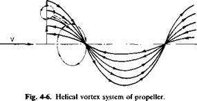
Consider the propeller shown in Fig. 4-6. From the Kutta-Joukowski theorem each element of the propeller blade must have a circulation of Г around it given by

dL = pe x Г dr. (4-26)

At the tips of the blades the section lifts must vanish. It therefore follows from Helmholtz’s theorem of vortex continuity that a vortex sheet must arise from each blade trailing downstream in a helical shape with a strength equal to the radialwise gradient of the bound circulation.

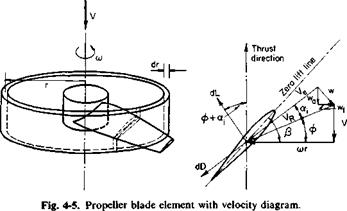
With reference once again to Fig. 4-5, the trailing vortex sheet induces the velocity w in the plane of the propeller. This velocity can be broken into two components, an axial component wa and a tangential component wt. Now consider the closed-line integral of the velocity taken around the dashed path shown in Fig. 4-6. Around the blades the integral will have a value of (—ВГ), В being the number of blades.

Along the vortex sheet the contribution from one side will cancel that from the other. Around the circle aft of the propeller the integral will have a value of

Jq 2wT(r, ф)г #.

The factor of 2 appears because the plane of this integral could have been taken infinitely far downstream of the propeller where the vortex sheet extends to infinity in both directions, hence induces twice the value that it would at the plane of the propeller. This, in fact, demonstrates that the line integral of the tangential velocity must increase discontinuously from zero in front of the propeller to its full value immediately behind it. This same conclusion results from consideration of the torque applied to the fluid by the propeller with the resulting change in angular momentum.

Because the dashed path of Fig. 4-6 does not cut any vortex sheets, it follows that the line integral of the velocity must vanish. Thus

f*2, it

ВГ = 2nrwT(r, ф) сіф. (4-27)

In the limit as В approaches infinity the velocity does not vary with ф so that

lim ВГ = Гж = 4nr wT(r).

B~> oo

The ratio of ВГ to Гда is known as Goldstein’s kappa factor к and can be obtained from Goldstein’s propeller theory. As stated before, however, it is approximated closely by Prandtl’s tip loss factor F. This factor is not to be confused with the effective radius В; F is a factor that varies with radius and allows the calculation of a continuous thrust distribution along the rotor radius.

Thus

Ajrr

Г = — F wT(r). (4-28)

D

The development of F as found in Ref. 2 is given by

F = – cos"1 ехрГ-f – (4-29)

n 2sin<£TJ

where фт is the helix angle at the tip. The bound circulation can also be related to the section lift coefficient by

Г = icC, F,

Vortex Theory of Propellers Подпись: Ф ~ «,)• Подпись: (4-30)

By combining the above with (4-28) we have

This equation is an implicit relationship for wT since Ve and oq are depen­dent on wT.

For reasons discussed later the induced velocity at the plane of the pro­peller is assumed to be normal to the resultant velocity in that location. Hence from the geometry of Fig. 4-5 the axial velocity wa can be calculated as

Подпись:Подпись: VTVortex Theory of Propellersor, in terms of VT,

(4-31)

Подпись: </> + oq = tan Подпись: 1 Я + wJV.T x — wT/VT Подпись: (4-32)

The angle ф + oq is given by

Подпись: К VT Подпись: x Подпись: 2-11/2 Подпись: (4-33)
Vortex Theory of Propellers Vortex Theory of Propellers

The resultant velocity Ve can be found from

Vortex Theory of Propellers

Hence, knowing a and P as a function of x and given a, we should be able to solve the system of Eqs. (4-29) through (4-33) for wT/VT, wjVT, (a, + ф), and VJVT. The thrust and power can then be calculated from

Подпись: Bp 2 Подпись:rR

corV^cCi cos (ф + a,)[£ + tan (ф + oq)] dr, о

or, in dimensionless form,

Kr=J a(^rj C‘ cos № + – rtl – £ tan (Ф + *i)] dx’ (4-34)

KP = J xcr^~^j C, cos (ф + a,)[fi + tan (ф + a,)] dx. (4-35)

The slope of the section lift curve a0 and the ratio of drag to lift є are functions of the local Mach and Reynolds numbers. However, their dependence on the Reynolds number, as far as propellers are concerned, can
normally be neglected. On the other hand, compressibility effects can be­come severe near the tip of a blade if the local Mach number exceeds the critical Mach, number. The estimation of e and a0 for M > Mcrit is often a difficult task because of the lack of sufficient experimental data. In the absence of specific data the following expressions can be used to estimate Cd and a0:

Cd – S0 + (ijC, + S2Cf

+ A Cd,

(4-36e)

AC, = K(M – Mcrit)4

(AC, = 0 if M < Mcrit),

(4-36b)

Mcrit = Mcrit0 – WjC,,

(4-36c)

ao — a0iJl + fl4^4 + <210M10),

(4-36d)

Подпись: where d0, дъ S2 MПодпись:= constants in airfoil drag polar,

= Mach number of section,

= critical Mach number,

= critical Mach number for C, = 0, = constant,

= constants,

= dCJda for M = 0.

For a NACA 0012 airfoil section typical values of these constants are

<50 = 0.0085,

К = 200,

II

О

°olac = 0.1 Cf deg,

S2 = 0.008,

a4 = 1.438,

crit„ = 0.725,

a10 = —4.29,

mY = 0.425,

C, = 1.4.

‘max

The effect of blade stall must also be considered in calculating CT and CP. Although it is possible to perform refined calculations by using lift curves extending beyond the stall, it is not considered worthwhile because of the uncertainties involved in determining С1т_ж; С1тшж depends critically on Mach number because of the occurrence of local shock stall and also varies considerably with blade roughness and irregularities in manufacture. It is recommended therefore that the C, m>i be used only as a limiting value on any calculated section C(.

Approximate Solution for a,-. The preceding equations are tedious to solve for wt or a; because of the implicit relationship of и,. Fortunately af can be

solved for directly if the angle a, is assumed to be small. From the geometry of Fig. 4-5

w, = Vrol, sin (Ф + a,).

Equating the above to Eq. (4-30) by using Ve ^ VR, we obtain

a. = i[-B + Jb2 + 4C] (4-37)

Vortex Theory of Propellers

where

and

c = gfloQg – 0)

8xF cos ф

Observe that for x = 1, F = 0, so that a, = /? — </> at the tip. Hence the C, at the tip vanishes. This also allows us to calculate the angle фт in the expression for F, Eq. (4-29):

Фт = Ф + «і(х = 1) = (4-38)

These equations for a blade with washout at the tips may not hold at low values of the thrust coefficient if [iT becomes negative. Hence in any numerical calculations it is recommended that фт not be allowed to become negative. If фт does become negative, we must use a small positive value for фт, say, approximately one degree.

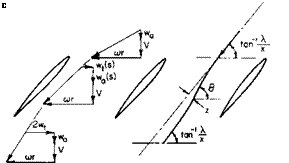
Normality in the Ultimate Wake. The velocity diagram in the ultimate wake of a propeller is shown in Fig. 4-7. Reference 3 shows that the resultant velocity and the induced velocity in the ultimate wake must be normal. This is apparently in conflict with the previous assumption of normality at the plane of the propeller. However, it is not so. We must remember that the wake behind the propeller contracts. The radius of a streamline from the axis at the propeller is larger than the radius of that same streamline in the ultimate wake. Hence to conserve angular momentum the average “2w(” immediately behind the propeller must be less than “2w,” in the ultimate wake. To circumvent the difficulties inherent in dealing with the ultimate wake normality is assumed in the plane of the propeller. The justification for this assumption lies in the fact that in the limit, as the number of blades become infinite, results from the vortex theory reduce to those obtained from momentum theory if normality is assumed in the plane of the propeller.

To show this let F = 1 (as В -> oo) so that

ВГ = 4n rwt.

From normality in the plane of the propeller

W, = i[cor – Jicor)2 – 4wa(V + vvj] The differential thrust is written:

dT = pBV(o>r — wt) dr.

A combination of these relations results in

dT = p(2nr dr^V + wa)2wa, which is in agreement with momentum theory.

Vortex Theory of Propellers

Corrections for Thickness and Wide-Blade Effects. As developed so far, the vortex theory of propellers is comparable to the lifting line theory of finite wings. For the typical aircraft propeller or helicopter rotor the theory is adequate. However, for broad-bladed propellers of high solidity it may be necessary to apply corrections to account for the blockage of the flow as it

passes through the blades and for the finite chord of the blades. To under­stand how these corrections are made, consider Fig. 4-8. Immediately in front of the propeller the velocity is composed of the free-stream velocity V,
the axial induced velocity wa, and the rotational velocity (or. As the flow enters the cascade of airfoils, the axial component must increase to satisfy continuity as the cross-sectional area of the channel decreases. As the flow progresses through the propeller, the tangential component of induced velocity increases from zero at the leading edge to its full value of 2иу at the trailing edge. Because of this, the flow traces a curved path which effectively reduces the camber of the sections. This correction to the camber can be determined graphically, but for purposes of numerical calculation expressions are developed to account for the variation of ну and thickness effects. The problem is linearized by calculating the effects separately. First consider the иу variation. It is assumed that ну varies linearly through the propeller from zero at the leading edge to 2wy at the trailing edge. If в is the slope of the flow at any point a distance of у from the leading edge, then approximately

Подпись: tan в =V + и-

cor — (y/c)2wT

Vortex Theory of Propellers

Thus the change in в from the leading edge to the trailing edge is

л z Л0

*7 "l" (4-39)

For a circular arc airfoil this corresponds to a reduction in the angle of attack of the zero lift line of

Ав

Да = т. (4-40)

Vortex Theory of Propellers Vortex Theory of Propellers

The effect of thickness is determined by approximating the airfoil with an ellipse of the same thickness-chord ratio. Again, if у is the distance from the leading edge,

From continuity

Vortex Theory of Propellers2nrV = V(y)^2nr – Btmax

The angle 9 is given approximately by

Подпись:-! V(y)

Vortex Theory of Propellers Vortex Theory of Propellers Подпись: 1 /2-І Подпись: (4-41)

cor

9 given by Eq. (4-41) traces out the path shown in Fig. 4-8. The departure of this path from a straight line is given by

Подпись: A x -г – = 9 — tan dy

Подпись: 7 “max Подпись: dy.
Vortex Theory of Propellers

or

Vortex Theory of Propellers

The effective change in the angle of attack of the section due to thickness is

By substituting (4-41) for 9 and performing the indicated integration we

obtain the results

Подпись: (4-42)4 А(Т I max

15 (A2 + x2) c

In the calculation of the performance of a given propeller the section angles of attack are reduced in the amounts given by (4-40) and (4-42). To produce a desired Г-distribution the section angles of attack should be increased by the amount of (4-42) and the camber ratio by (4-39).

The Effect of a Finite Hub. Goldstein’s solution and Prandtl’s approxi­mation to Goldstein’s solution assume that the action of the blades holds clear into the axis of rotation of the propeller. In other words, the propeller is assumed to have no hub. This is most often satisfactory, but in some applications in which the hub radius is appreciable with respect to the propeller radius a correction to the bound Г-distribution is required. The problem of the optimum propeller with a finite hub was first solved in Ref. 4. Here an infinitely long circular cylinder is concentric with the axis of the trailing helical vortex sheet and the strength of the vortex sheet is adjusted so that the velocities normal to the surface of the cylinder will
Vortex Theory of Propellers

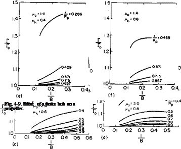
vanish. This additional boundary condition modifies Goldstein’s results for a helix of given pitch so that the slope of the bound Г-distribution is zero at the hub. These results are presented in Fig. 4-9. These factors are the ratios of Г with a hub to Г without a hub. Hence to account for the effect of a

finite hub we multiply Goldstein’s kappa factors or Prandtl’s F-factors by the factors of Fig. 4-9 and then proceed with the same analysis used in the zero hub case.

Figures 4-9a and b show the effect of different hub sizes on the circulation

distributions of two – and eight-bladed propellers. The notation is the same as in the reference and is defined as

Vortex Theory of Propellers

coR 1

rh = hub radius,

w = axial velocity of helical vortex surfaces = w0,

Notice that the departure from the zero hub case is much less for the eight-bladed propeller and is shown more clearly by Figs. 4-9c through /. Here, for constant values of r/Rp, the ratio of Г with a hub to Г without a hub is plotted versus the reciprocal of the number of blades.

Reference 3 presents the results of a comprehensive project on torpedo propellers but is, of course, applicable to any propeller. In this report it is shown that a finite Г can be maintained at the hub. For wake-operating, counterrotating propellers this is desirable. For single propellers in general, however, carrying a finite Г into the hub results in a hub vortex downstream of the propeller. The low pressure in the center of this vortex, acting on the rear face of the propeller hub or on any structure aft of the propeller, can detract seriously from the thrust of the blades. Hence for a single propeller with a large hub it is recommended that the bound circulation distributions be reduced to zero at the hub unless there is something like another pro­peller or a set of stator vanes downstream of the propeller to counteract the hub vortex.

Blade Element Theories

The simple momentum theory provides useful information regarding the action of a propeller but none for its detailed design. We usually resort to a blade element approach. The forces acting on a differential element of the blade are determined and then integrated over the radius in order to predict the thrust and torque characteristics of the propeller.

Blade Element Theories

A differential blade element of chord c and width dr, located at a radius r from the propeller axis, is shown in Fig. 4-5. The element is shown acting under the influence of cor, the linear velocity V, and vv. The three velocities add vectorially to produce a resultant velocity, Ve. The section has a geo­metric pitch angle of its zero lift line of [i. If we assume that V and cor are known, the problem is that of calculating w, because if tv is known a, can be calculated, hence the section angle of attack a. Knowing a, we can calculate C, and Cd> whence the differential lift and drag of the section follow. However, w depends on dL which in turn depends on w. Thus the problem is closely related to the finite wing problem but is more complicated because of the helicoidal geometry of the propeller.

Combined Momentum—Blade Element Theory A first approximation to w can be obtained by applying the previously developed momentum principles to an annulus of width dr and radius r. In addition, the angle <xt, as well as e, the drag-to-lift ratio of the section, is

assumed to be small, w, also, is assumed to vary only with the radius. With these assumptions, the thrust can be obtained from momentum principles as

dT = p(2nr drV + a, FK cos ф)2аіУя cos ф;

but for a propeller with В blades dT is also given by

dT = BjpVRca0(fS — ф — a,) cos ф dr.

By equating these two expressions we obtain

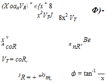
Подпись: (X oaaVR + «{x + 8 x2VTJ Ф)- 8x2 VT x v Be A coR a nR' VT = coR, yR = + *2ут, ф = tan-1 — X (4-19)

where

Подпись: aa0VR 8x2FT Подпись: ai = ^-lx +
Blade Element Theories Подпись: (4-20)

The induced angle of attack a, can be obtained from (4-19) as

If we are given the propeller geometry /? and c and the ratio of the forward velocity to the tip speed A, the induced angle of attack can be calculated from (4-20). Knowing this, we determine the angle of attack (P — ф — otj) from which C, and Cd are obtained. The thrust and power can then be predicted by

Подпись:Подпись: В P=2p VRcCt cos ф( 1 — є tan ф) dr,

Blade Element Theories Blade Element Theories

a>rV2RcCl cos ф(е + tan ф) dr,

Blade Element Theories

When CT and CP are multiplied by a2 and A3, respectively, these products are finite for A = 0. Note that

A parameter sometimes of interest in the analysis of a propeller is the average lift coefficient. Suppose in (4-21) that о and C, are independent of x. This equation can then be written as

KT = <rC, f x-sjl2 + x2 dx (for 6i0)

so that

Подпись: (4-23)ЪКТ

<т[(1 + A2)3/2 – A3]

Подпись: KT Blade Element Theories Подпись: £ tan ф) dx Подпись: (4-24)

The combined blade element momentum theory does not account for the loss of lift toward the tips of the blades. As in the finite wing, the lift on the propeller blades must go to zero at the tips. The vortex theory to be developed next does consider this boundary condition. However, for the combined blade element momentum theory the concept of an effective radius is used to account approximately for the loss of thrust toward the blade tips. It is assumed that the thrust acts only out to a radius of BR, so that Eq. (4-21) becomes

Equation (4-22) for the power becomes KP = xa(X2 + x2)C, cos ф(е + tan ф) dx

Jo

Подпись:-I – x<t(A2 + x2)Cdo cos ф dx,

Jb

where Cdo = Cd for C, = 0.

There are numerous rules and guides for the calculation of the effective dimensionless radius B. The use of В is, of course, an approximation, for the thrust must drop off continuously to zero at the tip. The value of В that most closely approximates the actual case would depend on the section cC, distribution of the propeller. Thus it is difficult to give a hard and fast rule
for its determination. Instead, it is recommended that a value of В = 0.97 be used for preliminary estimates.

The aerodynamics of propellers

The advent of V/STOL aircraft has resurrected in part the subject of propeller aerodynamics which was buried by the development of the turbo­jet engine. This chapter deals only with the propeller at zero angle of attack, that is, where its axis of rotation is aligned with the free-stream velocity. Corrections for angle of attack are developed in Chapter 8.

Classical Momentum Theory

Considerable insight into the action of propellers can be gained by the application of the momentum and energy principles developed in Chapter 2.

The aerodynamics of propellers

Fig. 4-1. Streamtube passing through a propeller.

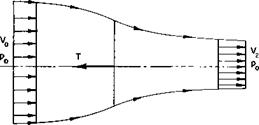
Consider the thrusting propeller shown in Fig. 4-1. In this simplified model the following is assumed:

1. The thrust loading is uniform over the propeller disk. This implies the limiting case of an infinite number of blades.

2. There is no rotation imparted to the flow. This would be approximated by a pair of counterrotating propellers.

73

3. A well-defined slipstream separates the flow passing through the propeller disk from that outside the disk.

4. Far ahead of and behind the propeller the static pressure in and out of the slipstream is equal to the undisturbed free-stream static pressure.

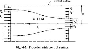
Consider a cylindrical control surface of radius R around the propeller, as shown in Fig. 4-2. R is assumed to be large in comparison to the propeller radius. The upstream and downstream planes are infinitely far removed from the propeller so that the propeller streamtube walls are parallel to the axis. The static pressure is constant in these planes and equal to the free – stream static pressure p0.

The aerodynamics of propellers

From continuity there must be a flow in through the side walls. This flux, Q, is given by

Q = V2nr2 + V0n(R2 – r2) – V0nR2 (4-1)

or

Q = nrV2 – V0). (4-2)

For large R the streamlines are nearly parallel to the axis. The transport of momentum in through the walls in the direction of the axis is thus pV0Q. Applying the momentum theorem, we therefore obtain

T — momentum flux out — momentum flux in,

or

T = nr2pV + n(R2 – r2)pV2 – ;tR2pV2 – nr2p(V2 – V0)V0, (4-3) or

T = pnr2V2(V2 – V0). (4-4)

In words these equations state that the propeller thrust is equal to the product of the mass rate of flow through the propeller and the increase in

velocity in the slipstream infinitely far in front of and behind the propeller.

Although the result may seem obvious, we cannot arrive at it simply by considering the propeller slipstream as a control surface. If such a procedure were done, the resultant of the static pressure acting on this surface in the thrust direction would have to be considered.

Now the thrust can also be expressed as

T = A Ap, (4-5)

where A is the propeller disk area and Ap is the discontinuous increase in the static (and total) pressure across the disk. Ap can be obtained by writing Bernoulli’s equation in front of and behind the propeller disk. The equation does not hold, of course, across the disk.

Po + ЇРУ о = P + ?pV

Po + kpv = P + ЇРУ і + Да

or

= W – Vl)

Подпись:= kiP(V2 – V0)(V2 + V0).

Also from continuity

nr2V2 = AV1.

Hence by combining (4-4) through (4-7)

V.-4*-

This important result of the momentum theory of propellers states that the velocity through a propeller is equal to the average of the velocities in its slipstream infinitely far in front of and behind the propeller. The increment added by the propeller to V0 at the disk, that is, V1 — V0, is referred to as the induced velocity w. In terms of w Eq. (4-4) with the aid of (4-8) becomes

T = pA(V0 + w)2w. (4-9)

This expression is easily remembered, for pA(V0 + w) is the mass rate of flow through the disk and 2w is the ultimate change in velocity of the flow.

In order to define an efficiency, expressions are needed for the power required by the propeller and the useful work it performs. By neglecting profile drag losses and losses associated with the trailing vortex system and applying the energy theorem to control surfaces far ahead of and behind the propeller, we evaluate the power that the propeller supplies to the fluid
as the difference in the flux of kinetic energy passing through the control surfaces.

P. = ±pA(V0 + w)l(V0 + 2w)2 – Ко]

= _pA(V0 + w)2w](V0 + w)

= T(V0 + xv). (4-10)

Hence the power supplied to the flow is simply the product of the propeller thrust and the local velocity at the point at which the thrust is being produced.

The useful power is defined as the product of the thrust and the free stream, or advance, velocity V0.

Puse = TV0.

Hence an ideal efficiency, щ, can be defined as

Подпись:1

1 + w/K0

Подпись: CT Подпись: T У AVI’ Подпись: (4-12)

The dimensionless velocity ratio, hence tfr, is purely a function of the propeller disk loading T/A divided by the dynamic pressure pV 1/2. If we define a dimensionless thrust coefficient CT by

then from (4-9) the induced velocity becomes

Подпись: (4-13)XV, /———

– = і(УГТСг – і).

An induced or ideal power coefficient, CPi, can also be defined by

C =_5_.

P’ У AVI

Подпись: Cp. = Cj-
The aerodynamics of propellers

With the help of (4-10), this can be written as

Подпись: (4-14)— – у-(Л + Cr + 1);

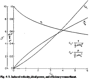
w/K0, CP(, and ri are presented in Fig. 4-3 as a function of CT. For a given

In a statically thrusting propeller CT, CPi, and >/, V0 = 0. For this case Eqs. (4-9) and (4-10) become

are meaningless, for

( T y/2

W-{2Pa) ’

(4-15)

J3/2

s/2pA

(4-16)

CT, these are the minimum values of CP or maximum values of which we can hope to obtain from a propeller.

Подпись: Fig. 4-3. Induced velocity, ideal power, and efficiency versus thrust.

Prediction of Thrust Available as a Function of Forward Speed

The aerodynamics of propellers The aerodynamics of propellers Подпись: 1/2-1
The aerodynamics of propellers

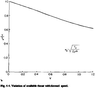
In the calculation of takeoff distance the variation of thrust with forward speed is required, and the momentum theory can provide a quick estimate of the available thrust. If it is assumed that the power required to overcome the profile drag of the blades and the power available from the engine do not vary with forward speed, the induced power absorbed by the propeller will be a constant. If a sub 0 refers to static conditions, then by equating (4-14) and (4-16) we have

The aerodynamics of propellers Подпись: A T + 4 — To Подпись: 1/2 Подпись: (4-17)
The aerodynamics of propellers

This can be expressed as

Подпись: "o Fig. 4-4. Variation of available thrust with forward speed.

The variation of thrust with forward speed, obtained from (4-17), is shown in Fig. 4-4. It will be observed that the available thrust decreases as the forward velocity increases.

Dynamic Pressure in Slipstream

One final item of interest, readily obtainable from momentum theory, is the dynamic pressure infinitely far downstream of the propeller in the slipstream:

Чаэ = iP(V0 + 2 w)2.

From (4-9)

so that

Подпись: Q <x>The aerodynamics of propellers(4-18)

Thus it is noted, and easily remembered, that the dynamic pressure in the ultimate wake of a propeller is equal to the free-stream dynamic pressure plus the disk loading T/А.

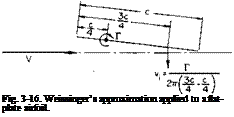
Approximate Lifting Surface Theory

Подпись: Fig. 3-16. Weissinger’s approximation applied to a flat-plate airfoil.

Consider a two-dimensional, flat plate airfoil with the distributed vorticity concentrated at the one-quarter-chord point, as shown in Fig. 3-16. Suppose

the boundary condition is satisfied only at the three-quarter-chord point so that

Г

Подпись: or

" 2b(c/2)F’ Г = ncaV,

Approximate Lifting Surface Theory Подпись: 2m.

so that

With this simple artifice, a result identical to more exact theory is obtained. Hence, if we were to concentrate the bound circulation at the one-quarter-chord line and satisfy boundary conditions only at the three – quarter-chord line, we might expect that for a finite wing the calculation of wing lift might agree closely with more exact calculations. Such is the case sometimes referred to as Weissinger’s approximation.

De Young [10] applies Weissinger’s approximation to the elliptic load distribution on a straight line and further assumes that the induced angle of attack is constant along the three-quarter-chord line and equal to the wing angle of attack a. With this assumed model, since C, is constant along
the wing, we need consider only the midspan value of the section C,. Integrating the contributions of the bound and trailing vortices at the mid­span location, the result is obtained that

dCL 2nAR ~da = 2 + £AR/7c’

where E is the complete elliptic integral of the second kind with modulus к and

i – tcAR

~ Vl + (TtAR/4)2’

The above is somewhat unwieldy to use in view of the £-function. Hence Ref. 10 assumes CL of the form

2ttAR

L* “ AR + 2/(AR)’

Подпись: Fig. 3-17. Lift curve slope for elliptic wings as predicted by various theories.

By matching the two expressions and their first derivatives with respect to

AR at AR = 0 and oo we have an easily handled expression for CLx as a function of CL :

Подпись: (3-55)2л AR

Cu ~ AR + 2(AR + 4)/(AR + 2)

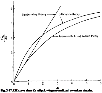
Equation (3-55) is offered as a first-order correction to lifting line theory for large aspect ratio wings or to slender wing theory for low aspect wings. Equations (3-37) (with a0 = 2k), (3-53), and (3-55) are compared in Fig. 3-17. Equation (3-55), considering its simplicity, agrees remarkably well with more exact results. By applying corrections to it for other than elliptical loadings from lifting line theory we can obtain a quick estimate of the lift curve slope of lifting surfaces in general.

Summary

Methods of estimating the characteristics of two- and three-dimensional airfoils have been developed in this chapter. For two-dimensional airfoils, the lift is linearly dependent on the angle of attack and on the camber ratio. A point on the airfoil, called the aerodynamic center, at which the aero­dynamic moment is constant, independent of lift, was found to exist.

For finite wings the slope of the lift curve decreases with decreasing aspect ratio. When the deflection of the trailing vortex sheet is accounted for in calculating the wing lift, it was found that a given wing can develop a limited lift coefficient, irrespective of stalling. This limiting CL increases approxi­mately linearly with aspect ratio.

Problems

1. Given an elliptic wing with a span of 40 ft and an aspect ratio of 4, the slope of the section lift curve is 0.1C,/deg. By use of suction BLC the wing is unstalled up to an angle of attack of 35°. At this angle, what is the wing CL? Account for the deflection of the trailing vortex sheet. What is the value of the midspan circulation at 150 mph at standard sea-level conditions? What is the value of CD. ?

2. Two two-dimensional airfoils are in tandem, that is, one behind the other. They are five-chord lengths apart. If each airfoil is at an angle of attack of 10° with respect to the free-stream velocity, what is the lift coefficient of each?

3. What is the critical Mach number of a thin circular arc airfoil with a 5% camber ratio at zero angle-of-attack?

4. Using an approach similar to slender wing theory, derive an expression for the lift on a cone.

Lifting Surface Theory for Slender Wings of Low Aspect Ratio

Lifting line theory is applicable only to wings of large aspect ratio of approximately four or more. For wings of lower aspect ratio we should resort to a lifting surface theory, which involves finding a potential flow to satisfy the Kutta condition all along the span but at the same time satisfying the boundary condition that the normal velocity components vanish every­where on the wing surface. The exact formulation and solution of the general lifting surface problem can be found in several references. Unfortunately, these formulations are rather unwieldy unless they can be programmed on a digital computer. Even then the task can be a formidable one.

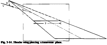
Подпись: Fig. 3-14. Slender wing piercing a transverse plane.

Instead of an exact lifting theory, some approximate developments can be quite useful. First, consider the limiting case of the slender pointed wing

shown in Fig. 3-14. Slender wing theories, developed in Refs. 7 and 8, assume that the flow is essentially two-dimensional in any transverse plane.

Подпись: 1 dp pdx-

Подпись: du, du: “Г + dt 1 dx,
Подпись: i,j = 1, 2, 3.

For this development it is convenient to write the equations of motion (2-11) by using a repeated subscript notation.

The repeated subscript j indicates that this term is to be summed over the indicated range of j. In terms of the velocity potential, the above equation becomes

Multiplying the above by dxt and integrating, we obtain

-г – + t(u2 + v2 + w2) + – = constant. (3-48)

ct 2 p

Now consider two points on the wing, one on the lower surface and the other on the upper surface directly above the first. In view of the assumption of two-dimensional flow in a transverse plane, и and w at the two points are equal, whereas v and the velocity potential ф on the lower surface are the negative of their values on the upper surface. Hence, if Ap is the pressure difference from the upper to lower surface, it follows from (3-48) that

(3-49)

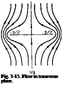
дф/dt is evaluated by calculating the flow in the transverse plane of Fig. 3-13. This flow is illustrated in Fig. 3-15. As the wing penetrates this plane, the dimension b varies, thereby causing a change in ф. Hence (3-49) can be expressed as

. „ дф dx

Ap = 2p^- — dx dt

Подпись: (3-50)db дф

pV dx db

The problem is that of finding the velocity potential for two-dimensional flow past a flat plate normal to the flow with a free-stream velocity of Fa.

Lifting Surface Theory for Slender Wings of Low Aspect Ratio

This problem can be easily solved by the methods of conformal mapping. However, the solution is beyond the scope of this book, and instead we shall obtain it by recalling that the downwash produced by a vortex sheet trailing from an elliptic Г-distribution is a constant. Thus, if an equal and opposite velocity is added to this flow field, the velocity along the vortex sheet will be zero; but this is identical to the boundary condition along the flat plate. Hence, if the Г-distribution is

the constant downwash induced in the ultimate wake is

Подпись: = Го b = bVa sin в, w

But this is to equal Fa; thus

Г

where

У

Подпись: ФLifting Surface Theory for Slender Wings of Low Aspect Ratio
"Г’*

Подпись: Fig. 3-15. Flow in transverse plane.

From (3-52) it can be observed that Ap varies linearly with the longitudinal rate of change of b. Note also that Ap is constant on rays emanating from

the apex which pass through constant values of y/(b/2). It can also be seen that Ap is infinite at the edges of the sheet. It is argued in Ref. 9 that (3-52) holds only up to the maximum value of b; fimax, and that beyond that, if b diminishes, the surface contributes nothing to the wing characteristics.

If (3-52) is integrated over the wing surface, it will be found that the span – wise loading is elliptical so that

^ AR a, 2

(3-53)

C2.

я AR

(3-54)

From (3-52) we can also determine the center of pressure for the slender wing. If this is done, we shall find that the center of pressure shifts forward for low aspect ratios. Unlike CL and CDi, the center of pressure depends on the planform shape.

The results, of course are strictly applicable only for the limiting case of zero aspect ratio. However, the result that the spanwise loading is elliptical suggests an approximate model that may hold throughout a wide range of aspect ratios.