Category Aerodynamics of Wings and Bodies

Methods of Solution

Here we shall make a short review of some of the methods that have been proposed and used for solving the transonic nonlinear small-disturb­ance equations. The only case, so far, that has been found amenable to a mathematically exact treatment is the two-dimensional, for which it is possible to transform the nonlinear problem to a linear one by going to the hodograph plane. Let

0

n>


where Kx is given by (12-47). The quantities її and w represent (to first order), with appropriate constants, the components of the difference between the local velocity and the speed of sound. Thus, on the sonic line

її = 0, (12-55)

with w taking on any value, and

и = К i, w = 0

at infinity.

We may then write (12-12) with the aid of the condition of irrotation – ality as follows:

— йїїх + Wf = 0, (12-57)

щ = wx. (12-58)

We shall now transform this system so that и and w appear as the depend­ent variables. For this purpose we introduce a function ф(й, w) such that

x = fc, (12-59)

Ґ = Фіг – (12-60)

It will be shown subsequently that the irrotationality condition (12-58) is thereby automatically satisfied. For from (12-59) and (12-60) it follows that

dx — фгіи dll ~J – ^pu w dv)j

(12-61)

djf -— фууй dll Фитй) dWj

(12-62)

which show that dx =

0 for

dw = {Фий/Фиъй) dll.

(12-63)

and that df = 0 for

du = —dw(fow/ifrwii).

(12-64)

Thus

– (a

U^p

m du

/ dx=0 [Фьт V’wwKV’wm/V’uuj)] dll

_ Фиу)

~ D ’

(12-65)

where

D — фиифигш (фиш)

is the functional determinant (Jacobian).

Similarly, it is found by use of (12-64) that

which confirms (12-58).

Proceeding in this manner we find that

^x — fiww/D

and

Щ = Фш/D-

Hence (12-57) transforms to

— Www + Фш = 0,

which is known as Tricomi’s equation after Tricomi (1923), who first investigated its properties. It is seen that the linear equation (12-69) preserves the mixed subsonic-supersonic character of the original equation because it is hyperbolic for її > 0 and elliptic for м < 0. However, the linearization of the equation has not been bought without considerable sacrifice to the simplicity in the application of the boundary conditions. In fact, solutions have so far been obtained only for some very simple shapes.

To illustrate the difficulties involved, the boundary conditions for a simple wedge are formulated in Fig. 12-7. The case of a subsonic free stream for which Кi < 0 is illustrated. In view of (12-54) the point й = Ki, = 0 represents infinity in the physical flow field so that, following

Fig. 12-7. The transonic flow around a nonlifting single wedge.

the definitions (12-59) and (12-60), the derivatives of ф must be infinite at this point, i. e., the solution must have a singularity at (Кb 0). The form of this may be determined from the linearized subsonic solution, except for M = 1 which requires special treatment.

The transonic wedge solution has been worked out for M less than unity by Cole (1951) and by Yoshihara (1956), for M = 1 by Guderley and Yoshihara (1950), and for M > 1 by Yincenti and Wagoner (1952). The results for the drag coefficient are plotted in Fig. 12-8 together with experimental data obtained by Bryson (1952) and Liepmann and Bryson (1950). As seen, the agreement is excellent.

Fig. 12-8. Theoretical and experimental results for the drag of single-wedge airfoils. (From Spreiter and Alksne, 1958. Courtesy of the National Aero­nautics and Space Administration.)

The hodograph method is not very useful for axisymmetric flow, since the factor 1/p in the second term of (12-26) makes the equation still non­linear after transformation to the hodograph plane. Because of such limitations, a considerable effort has been expended in finding methods that work directly in the physical plane. The solutions developed so far are all based on one or more approximations. In the method for two­dimensional flow proposed by Oswatitsch (1950) and developed in detail by Gullstrand (1951), the differential equation is rewritten as an integral equation by the aid of Green’s theorem, and the nonlinear term is approxi­mated under the implicit assumption that the value of an integral is less sensitive to errors in the approximations than is a derivative. Further improvements in this method have been introduced by Spreiter and Alksne (1955).

An approximation of a radically different kind was suggested by Os- watitsch and Keune (1955a) for treating the flow on the forward portion of a body of revolution at M = 1. In the differential equation (12-31) for M = 1,

— (7 + l)<Px<Pxx + – Vr + <Prr = 0, (12-70)

the nonlinear term was approximated by

(T – j – 1)iPx(Pxx = ^p*Pxj (12“71)

where the constant Xp is to be suitably chosen. The justification of this approximation is that on the forward portion of the body the flow is found to be everywhere accelerating at a fairly constant rate. Also, the resulting differential equation is parabolic, which intuitively is satisfying as an intermediate type between the elliptic and hyperbolic ones. The constant Xp was chosen arbitrarily (but in a way consistent with the similarity law) so as to give good agreement with the measured pressure distribution in one case, and it was proposed to use this as a universal value in other cases.

Fig. 12-9. Pressure distribution on a cone cylinder at iff = 1. (From Spreiter and Alksne, 1959. Courtesy of National Aeronautics and Space Administration.)

Maeder and Thommen (1956) also used the approximation (12-71) for flows with M slightly different from unity and suggested a new, but still arbitrary, rule for determining Xp.

An interesting extension of Oswatitsch’s method, which removes the arbitrariness in selecting Xp, has been presented by Spreiter and Alksne (1959). In this the parabolic equation resulting from the approximation (12-71) is first solved assuming Xp constant, and the value of и = <ря is calculated on the body. Now (7 + 1 )ux is restored in place of Xp and a nonlinear differential equation of first order is obtained for u, which may be solved numerically. As an example, the pressure distribution on a slender cone-cylinder calculated this way is shown in Fig. 12-9 together with values obtained from the theory by Oswatitsch and Keune (1955) and measured values. As seen, the agreement with the improved theory is excellent and considerably better than with the original one.

Spreiter and Alksne (1958) also employed this technique with consider­able success for two-dimensional flow, and for flows that have a Mach number slightly different from unity. In the latter case they replaced the nonlinear term

[1-М2 – M2(7 + l)Vx]Vtx (12-72)

by

X<p„, (12-73)

and proceeded similarly to solve the resulting linear equation with X con­stant. Thereupon (12-72) was resubstituted into the answer, producing a nonlinear first-order differential equation for и = <px as before. They were able to show that in the two-dimensional supersonic case, this gave an answer that was identical to that given by simple-wave theory.

The Kutta Condition and Lift

As is familiar to every student of aerodynamics, Joukowsky and Kutta discovered independently the need for circulation to render the two­dimensional, constant-density flow around a figure with a pointed trailing edge physically reasonable. This is a simple example of a scheme for fixing the otherwise indeterminate circulation around an irreducible path in a doubly connected region. It is one of a number of ways in which viscosity can be introduced at least indirectly into aerodynamic theory without actually solving the equations of Navier and Stokes. The circulation gives rise to a lift, which is connected with the continually increasing Kelvin impulse of the vortex pair, one of the vortices being the circulation bound to the airfoil, while the other is the “starting vortex ” that was generated at the instant the motion began.

image60

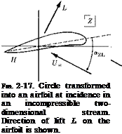
With respect to the lifting airfoil, we reproduce a few important results from Sections 7.40-7.53 of Milne-Thompson (1960). Let the profile and the circle which is being transformed into it be related as shown in Fig. 2-17.

It is assumed that the transformation

£=f + ^ + p + — -> (2-156)

which takes the circle into the airfoil, is known. It can be proved that the resulting force is normal to the oncoming stream and equal to

L = pt/„r. (2-157)

Here Г is the circulation bound to the airfoil, which incidentally may or may not satisfy the full Kutta condition of smooth flow off from the trailing edge. If this condition is entirely met, which is equivalent to neglecting the effect of displacement thickness of the boundary layer and’ the wake thickness at the trailing edge, then the circulation is given by

Г = ітгі/^а sin <*z. l.- (2-158)

All the quantities here are defined in the figure. In particular, az. L. is the angle of attack between the actual stream direction and the zero-lift (Z. L.) direction, determined as a line parallel to one between the center of the circle in the f-plane and the point Hi which transforms into the airfoil trailing edge. Combining (2-157) and (2-158), we compute the lift

L = 4wpl7^a sin «z. l.- (2-159)

From this we find that the lift-curve slope, according to the standard aeronautical definition, is slightly in excess of 2ir, reducing precisely to 2ж when the airfoil becomes a flat plate of zero thickness, i. e., when the radius a of the circle becomes equal to a quarter of the chord.

The airfoil is found to possess an aerodynamic center (A. C.), a moment axis about which the pitching moment is independent of angle of attack. This point is located on the Z-plane as shown in Figs. 7.52 and 7.53 of Milne-Thompson (1960). The moment about the aerodynamic center is

MA. C. = — 2жрІІ212 sin 27, (2-160)

where

ai = (le~iy)2. (2-161)

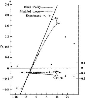
Figure 2-18 gives some indication of the accuracy with which lift and moment can be predicted. The theoretical value of zero for drag in two dimensions is the most prominent failure of inviscid flow methods. It represents a nearly achievable ideal, however, as evidenced by the lift-to – drag ratio of almost 300 from a carefully arranged experiment, which is reported on page 8 of Jones and Cohen (1960).

image62

Fig. 2-18. Comparisons between predicted and measured lift coefficients and quarter-chord moment coefficients for an NACA 4412 airfoil. “Usual theory” refers to Theodorsen’s procedure, whereas the modifications involve changing the function е(ф) so as to make circulation agree with the measured lift at a given angle of attack. [Adapted from Fig. 9 of Pinkerton (1936).]

More information will be found in Chapter 4 of Thwaites (1960) on refined ways of calculating constant-density flow around two-dimensional airfoils. In particular, these include reference to a modern theory by Spence and others which makes allowance for the boundary layer thickness and thus is able to carry the calculation of loading up to much higher angles of attack, even approaching the stall.

General Slender Body

For a general slender body we assume that the body surface may be defined by an expression of the following form

B(x, y, z) = B(x, у/є, z/e) = 0, (6-41)

where e is the slenderness parameter (for example, the aspect ratio in the case of a slender wing and the thickness ratio in the case of a slender body of revolution). With the definition (6—41), a class of affine bodies with a given cross-sectional shape is studied for varying slenderness ratio e, and the purpose is to develop the solution for the flow in an asymptotic series in € with the lowest-order term constituting the slender-body approxima­tion. In the stretched coordinate system

V = 2//e, 2 = z/« (6-42)

the cross-sectional shape for a given x becomes independent of e. From the results of Section 6-4 it is plausible that the inner solution would be of the form

Ф* = Ux[x + Є2Ф2ІХ, У, z) + ■ • • ], (6-43)

that is, there will be no first-order term. The correctness of (6-43) will become evident later from the self-consistency of the final result. For a steady motion the condition of tangential flow at the body surface requires that the outward normal to the surface be perpendicular to the flow velocity vector:

image87

Or, upon introducing (6-42) and (6-43) and dropping higher-order terms,

Bx + B&iy + ВІФІі = 0. (6-45)

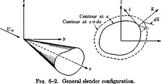
This relation may be put into a physically more meaningful form in the following manner. Introduce, temporarily, for each point on the contour considered, a coordinate system n, s such that n is in the direction normal to, and 5 tangential to, the contour at the point, as shown in Fig. 6-2. Obviously, (6-45) then takes the form

Bx + ВкФІк = 0. (6-46)

Let dn denote the change, in the direction of n, of the location of the contour when going from the cross section at ж to the one at x + dx. Moving along the body surface with dS = 0 we then have

dB = Bx dx + Bn dn = 0. (6-47)

Upon combining (6-46) and (6-47) we obtain

*;, = g. (e-48)

a condition that simply states that the streamline slope must equal the surface slope in the plane normal to the surface.

By introducing (6-43) into the differential equation (1-74) for Ф we find that Ф2 must satisfy the Laplace equation in the 5, г-plane:

^2vv + Фггг = 0. (6-49)

A formal solution may be obtained by applying (2-124). (This solution was deduced by using Green’s theorem in two dimensions.) Thus

where index 1 denotes dummy integration variables as usual, and

As in the body-of-revolution case the function $2(x) must be obtained by matching. Note that (6-50) is in general not useful for evaluating Ф2, since only the first term in the integrand is known from the boundary condition on the body. Nevertheless, it can be used to determine Ф2 for large F, since then d/dnlnr1 may be neglected compared to In Fx and, furthermore, fi may be approximated by F. Hence the outer limit of the inner solution becomes

(6-53)

which is the same as the solution (6-11) for an axisymmetric body having the same cross-sectional area distribution as the actual slender body. We shall, following Oswatitsch and Keune (1955), term this body the equivalent body of revolution. By matching it will then follow that <?2(я) must be identical to that for the equivalent body of revolution. We have by this proved the following equivalence rule, which was first explicitly stated by Oswatitsch and Keune (1955) for transonic flow, but which was also implicit in an earlier paper by Ward (1949) on supersonic flow:

(a) Far away from a general slender body the flow becomes axisymmetric and equal to the flow around the equivalent body of revolution.

(b) Near the slender body, the flow differs from that around the equivalent body of revolution by a two-dimensional constant-density crossflow part that makes the tangency condition at the body surface satisfied.

Proofs similar to the one given here have been given by Harder and Klunker (1957) and by Guderley (1957). The equivalence rule allows great simplifications in the problem of calculating the perturbation velocity potential

First, the outer axisymmetric flow is immediately given by the results of the previous section. Secondly, the inner problem is reduced to one of two-dimensional constant-density flow for which the methods of Chapter 2 may be applied. The following composite solution valid for the whole flow field has been suggested by Oswatitsch and Keune [cf. statement (b) above]: Let <pe denote the solution for the equivalent body of revolution and <P2 the inner two-dimensional crossflow solution that in the outer limit becomes <p2 ~ (1/27Г)S'(x) In r. Then the composite solution

<pc = <Pe + <p2 — lnr (6-55)

holds in the whole flow field (to within the slender-body approximation).

As in the case of a body of revolution, quadratic terms in the crossflow velocity components must be retained in the expression for the pressure, so that (cf. Eq. 6-23)

Cp = — 2<(>x — ip% — ip. (6-56)

In view of the fact that the derivation given above did not require any specification of the range of the free-stream speed, as an examination of the expansion procedure for the inner flow will reveal, it should also be valid for transonic flow. As will be discussed in Chapter 12, the difference will appear in the outer flow which then, although still axisymmetric, must be obtained from a nonlinear equation rather than from the linearized (6-21) as in the sub – or supersonic case. The form of the differential equation for the outer flow does not affect the statements (a) and (b) above, how­ever, and it turns out that the validity of the equivalence rule is less restricted for transonic than for sub – or supersonic flow so that it can then also be used for configurations of moderate aspect ratio provided the flow perturbations are small.

Some Geometric or Kinematic Properties of the Velocity Field

Next we specialize for the velocity vector Q two integral theorems which are valid for any suitably continuous and differentiable vector field.

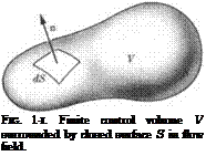
1. Gauss’ Divergence Theorem. Consider any volume V entirely within the field enclosed by a single closed bounding surface S as in Fig. 1-1.

j^Q-ndS = yyy (V ■ Q)dV. (1-14)

S ■ V

Here n is the outward-directed unit normal from any differential element of area dS. This result is derived and discussed, for instance, in Sections 2.60 and 2.61 of Milne-Thompson (1960). Several alternative forms and some interesting deductions from Gauss’ theorem are listed in Section 2-61. The theorem relates the tendency of the field lines to diverge, or spread out within the volume V, to the net efflux of these lines from the boundary of V. It might therefore be described as an equation of continuity of field lines.

2.

Подпись: Here Подпись: JJn ■ (V X Q) dS. S Подпись: (1-15)
image5

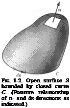
Stokes’ Theorem on Rotation. Now we consider a closed curve C of the sort employed in (1-12) and (1-13), except that the present result is instantaneous so that there is no question of a moving path composed of the same particles. Let S be any open surface which has the curve C as its boundary, as illustrated in Fig. 1-2. The theorem refers to the circulation around the curve C and reads

(1-16)

is called the vorticity and can be shown to be equal to twice the angular velocity of a fluid particle about an axis through its own centroid. The theorem connects the spinning tendency of the particles lying in surface S with the associated inclination of the fluid at the boundary of S to circulate in one direction or the other. Sections 2.50 and 2.51 of Milne-Thompson (1960) provide a derivation and a number of alternative forms.

Подпись: FIG. 1-2. Open surface S bounded by closed curve C. (Positive relationship of n- and ds-directions as indicated.)
Подпись: FIG. 1-І. Finite control volume V surrounded by closed surface S in flow field.

1-4 The Independence of Scale in Inviscid Flows

Подпись: FIG. 1-3. Two bodies of different sizes but identical shapes and motions.

Consider two bodies of identical shape, but different scales, characterized by the representative lengths h and /2, moving with the same velocity Qb through two unbounded masses of the same inviscid fluid. See Fig. 1-3. This motion is governed by the differential equations developed in Section 1-1 plus the following boundary conditions: (1) disturbances die out at infinity, (2) Qn = Qb • n at corresponding points on the two surfaces, n being the normal directed into the fluid.

We first treat the case of a steady flow which has gone on for a long period of time so that all derivatives with respect to t vanish. We can then apply the Newtonian transformation, giving the fluid at infinity a uniform motion minus Qb and simultaneously bringing the body to rest. Thus the boundary condition No. 2 becomes Qn = 0 all over the surfaces. We take the differential equations governing these two similar problems and make the following changes of variable: in the first case.

xx

= x/h,

<ci

II

Zi = z/h;

(1-17)

in the second case, *2

= x/h,

у

z2 = z/l2-

(1-18)

In the dimensionless coordinate systems the two bodies are congruent with each other. Moreover, the differential equations become identical. That is, for instance, continuity reads, in the first case,

Подпись:Подпись: (1-20)BjpU) , d{pVl, аШ1 = о

dxi dyi dz і

and in the second case,

d(pU) , dJpV) d(pW) =

dx2 dy2 dz2 ‘

We are led to conclude, assuming only uniqueness, that the two flows are identical except for scale. Velocities, gas properties, and all other dependent variables are equal at corresponding points in the two physical fields. This is a result which certainly seems reasonable on grounds of experience.

The same sort of reasoning can be extended to unsteady flows by also scaling time in proportion to length:

Xt = x/h, Ух = у/lx, zx = z/l 1, tx = t/lx, (1-21)

x2 = x/l2, 2/2 = y/h, z2 = z/l2, t2 = t/l2, (1-22)

in the two cases. With regard to boundary conditions, it must also be specified that over all time Qb(h) in the first case and Qbih) are identical functions.

Evidently, it makes no difference what the linear scale of an ideal fluid flow is. In what follows, therefore, we shall move back and forth occasion­ally from dimensional to dimensionless space and time coordinates, even using the same symbols for both. A related simplification, which is often encountered in the literature, consists of stating that the wing chord, body length, etc., will be taken as unity throughout a theoretical develop­ment; the time scale is then established by equating the free-stream to unity as well.

One important warning: the introduction of viscosity and heat conduc­tion causes terms containing second derivatives, the viscosity coefficient, and coefficient of heat conductivity to appear in some of the governing differential equations. When dimensionless variables are introduced, the Reynolds number and possibly the Prandtl number[2] appear as additional
parameters in these equations, spoiling the above-described similarity. The two flows will no longer scale because the Reynolds numbers are differ­ent in the two cases. Even in inviscid flow, the appearance of relaxation or of finite reaction rates introduces an additional length scale that destroys the similarity. It is satisfactory, however, for real gas which remains either in chemical equilibrium or in the “frozen” condition thermody­namically.

If shock waves and/or vortex wakes are present in – the field, it can be reasoned without difficulty that they also scale in the same manner as a flow without discontinuities. An excellent discussion of this whole subject of invariance to scale changes will be found in Section 2.2 of Hayes and Probstein (1959). Finally, it might be observed that differences between the two flows in the ambient state of the fluid at infinity, such as the pres­sure, density, and temperature there, may also be included in the scaling by referring the appropriate state variables to these reference values. The Mach numbers in the two flows must then be the same.

Unsteady Flow

12- 1 Statement of the Problem

Chapters 4 through 12 have dealt with aerodynamic loading due to uniform flight of wings and bodies. Obviously no air vehicle remains indefinitely bathed in steady flow, but this idealization is justified on the basis that the time constants of unsteady motion are often very long compared to the interval required for transients in the fluid to die down to imperceptible levels. There exist important phenomena, however, where unsteadiness cannot be overlooked; rapid maneuvers, response to atmospheric turbulence, and flutter are familiar instances. We therefore end this book with a short review of some significant results on time – dependent loading of wings. These examples merely typify the extensive research that has lately been devoted to unsteady flow theory, both linearized and more exact. We hope that the reader will be able to construct parallels with steady-state counterparts and thus prepare himself to read the literature on oscillating nonplanar configurations, slender bodies, etc.

Let irrotationality be assumed, under the limitations set forth in Sec­tions 1-1 and 1-7. The kinematics of the unsteady field are then fully described by a velocity potential Ф, governed by the differential equation (1-74), from which the speed of sound is formally eliminated using (1-67). (We let Я = 0 here.) Pressure distributions and generalized aerodynamic forces follow from (1-64).

Flow disturbances in a uniform stream

Ф? = U„x (13-1)

are generated by a thin lifting surface (Fig. 13-1), which is performing rapid, small displacements in a direction generally normal to its x, y-plane projection. Thus the wing might be vibrating elastically, undergoing sud­den roll or pitch aerobatics, or an encounter with gusty air might give rise to a situation mathematically and physically analogous to vibrations.

With zu and zi as given functions of position and time, we have no diffi­culty in reasoning that the boundary conditions which generalize the steady-state requirement of flow tangency at the surface (cf. 5-5) read as follows:

Фг{х, у, z„, t) = Фх(х, у, zu, t) + Фу{х, у, zu, t) + Фг(ж, у, zi, t) = ^ Фх{х, у, zh t) + ~ Фy{x, y, zi, t) + ^

for (x, y) on S. There is the usual auxiliary condition of vanishing dis­turbances at points remote from the wing and its wake, but for compressible fluid this must be refined to ensure that such disturbances behave like outward-propagating waves. The Kutta-Joukowsky hypothesis of con­tinuous pressure at subsonic trailing edges is also applied, although we should observe that recent evidence (Ransleben and Abramson, 1962) has cast some doubt on its validity for cases of high-frequency oscillation.

Provided that there are no time-dependent variations of profile thick­ness, the upper and lower surface coordinates can be given by

Zu = eju(x, y, t) = т$(х, у) + el{x, y, t) (13-3)

Zi = eji(x, y, t) = —T$(x, y) + eh{x, y, t).

Here e is a dimensionless small parameter measuring the maximum cross­wise extension of the wing, including the space occupied by its unsteady displacement. Angle of attack a (5-1) can be thought of as encompassed by the 0-term; g and h are smooth functions as in steady motion; their x – and y-derivatives are everywhere of order unity; the ^-derivative of h will be discussed below.

Recognizing that in the limit € —» 0 the wing collapses to the x, y-plane and the perturbation vanishes, we shall seek the leading terms by the method of matched asymptotic expansions. Let the inner and outer series be written

Ф0 = TJ«,[x + «Ф?(ж, у, z, t) + • • •], (13-4)

Ф* = Ux{x + еФгх(ж, y, z,t) + ■ ■ •], (13-5)

where

z = z/e, (13-6)

as in earlier developments. The presence of a uniform stream, which is clearly a solution of (1-74), has already been recognized in the zeroth – order terms in (13-4) and (13-5).

When we insert (13-3) into (13-2), a new question arises as to the size of dju/dt, that is of dh/dt. These derivatives may normally be expected to control the orders of magnitude of the time derivatives of Ф, hence of the terms that must be retained when (13-4)-(13-5) are substituted into (1-74). Here we shall avoid the complexities of this issue by requiring time and space rates of change to be of comparable magnitudes. For example, within the framework of linearized theory a sinusoidal oscillation can be represented by[10]

l{x, y, t) = t{x, y)eiat. (13-7)

The combination of (13-7) with (13-2), followed by a nondimensionaliza – tion of Ф* and Л through division by JJX and typical length l, respectively, produces a term containing the factor

k = (13-8)

Here к is known as the reduced frequency and our present intention is to specify that к = 0(1). For the rich variety of further reductions, even within the linearized framework, that result from other specifications on the magnitudes of к, M, etc., we cite Table I, Chapter 1, of the book by Miles (1959).

With the foregoing limitation on sizes of time derivatives, we find that the development of small-perturbation unsteady flow theory parallels the steps (5-6) through (5-31) quite closely. Thus the condition that vertical velocity W must vanish as « —> 0 shows, as in (5-12), that Ф] must be independent of 2, say

ФІ = Vdx, У, t). (13-9)

By combining (13-3) with (13-2), we conclude that Ф| is the first term to possess a nonzero boundary condition,

The differential equation

= 0 (13-11)

% + l*l dx Ux dt J

requires a solution linear in z; thus

for z > Ju, with a similar form below the lower surface. As in steady- flow, the z-velocities are seen to remain unchanged along vertical lines through the inner field, and it will be shown to serve as a “cushion” that transmits both W and pressure directly from the outer field to the wing.

It is an easy matter to extract the linear terms from (1-74) and derive the first-order outer differential equation

By matching with W derived from (13-12), we obtain indirectly the fol­lowing boundary conditions:

*;.<«, o+,« = § + £#

dfi. 1 dji

(7« dt

Moreover, matching Ф itself identifies with the potential Ф[ at the inner limits z = 0±.

The linear dependence of Ф( on /„ and fi, evident from (13-14), suggests that, in a small-perturbation solution which does not proceed beyond first order in e, we should deal separately with those portions of the flow that are symmetrical and antisymmetrical in г [cf. (5-32) or Sections 7-2 through 7-3]. Indeed, one may even isolate that part of h(x, y, t) from (13-3) that is both antisymmetrical and time-dependent. This we do, realizing that we may afterward superimpose both the thickness and lifting contribu­tions of the steady field, but that neither has any first-order influence on the unsteady loading.

We again adopt a perturbation potential, given by

еФ? = <p(x, y, z, i)

and satisfying, together with proper conditions at infinity, the following system:

for (x, y) on S. Corresponding to the pressure difference, has a discon­tinuity through S. As we shall see below, the Kutta-Joukowsky hypothesis also leads to unsteady discontinuities on the wake surface, which is ap­proximated here by the part of the x, y-plane between the downstream wing-tip extensions.

Finally, a reduction of (1-64) and matching, to order e, of Ф or Фх shows that

Cp = —2<px – JLVI + 0(e2) (13-18)

throughout the entire flow. (From Chapter 6, the reader will be able to reason that the small-perturbation Bernoulli equation again contains non­linear terms when used in connection with unsteady motion of slender bodies rather than wings.)

13- 2 Two-Dimensional, Constant-Density Flow

The best-known of the classical solutions for unsteady loading is the one, found almost simultaneously by five or six authors in the mid-1930’s, for the oscillating thin airfoil at M = 0. In this case of nearly constant density, a key distinction disappears between the steady and unsteady problems because the flow must satisfy a two-dimensional Laplace equation

<Pxx + <Pzz = 0. (13-19)

We may accordingly rely quite heavily on the results for a steadily lifting airfoil from Section 5-3, particularly on (5-58) and (5-73), which supply the needed inversion for the oscillatory integral equation while simul­taneously enforcing Kutta’s condition at the trailing edge.

With the lifting surface paralleling the ж, г/-р1апе between x = 0 and c, it can be assumed from (13-17) that <pz(x, 0, t) is known over that area and given by (dimensionless)

w0(x, t) = ib0(x)e’at for 0 < x < c. (13-20)

The perturbation field has <p and и antisymmetric in z, and allowance must be made for ^-discontinuities through the x, y-plane for x > 0. Hence, (13-19) and all other conditions can be satisfied by a vortex sheet similar to the one described by (5-58) but extended downstream by replacing the upper limit with infinity. Equations (13-17) and (13-20) are intro­duced through

For later convenience, we define an integrated vortex strength

Г(ж, t) = ( У(хі, t) dxі = 2 f 4>x(xi, 0+, t) dxi Jo Jo

= 2ф, 0+, t), (13-23)

and note that Г(с, t) is the instantaneous circulation bound to the airfoil.

From (13-18) and the antisymmetry of Cp in z, we deduce that a (physi­cally impossible) discontinuity of pressure through the wake is avoided only if

<Px + <Pt = 0, (13-24)

for x > c along г = 0+. Equation (13-24) is a partial differential expres­sion for <p(x, 0+, t), which is solved subject to continuity of <p at the trailing edge by

ф, 0+, t) = * (с, 0+, t – ■ (13-25)

From (13-23) and (13-25) are derived the further relations for the wake: Г(х, t) = T(c, t – > (13-26)

У(х, t) = — Vt (c, t – . (13-27)

Equation (13-27) has the obvious interpretation that wake vortex ele­ments are convected downstream approximately at the flight speed U„, after being shed as countervortices from the trailing edge at a rate equal to the variation of bound circulation.

where[11]

We next introduce (13-27) into (13-21) and use the assumption that a linear, simple harmonic process has been going on indefinitely to replace all dependent variables with sinusoidal counterparts and cancel the com­mon 4 Indicial Motion in a Compressible Fluid

In the analysis of linear systems there exists a well-known duality between phenomena involving simple harmonic response and “indicial” phenomena—situations where an input or boundary undergoes a sudden step or impulsive change. Fourier’s theorem enables problems of one type to be treated in terms of solutions of the other, and this is frequently the

most useful avenue to follow in unsteady wing theory. There are cases, however, when a direct attack on the indicial motion is feasible.

As a particularly simple indicial problem, let us consider the initial development of flow near the upper surface of a wing (e. g., Fig. 7-1) when a step change occurs in the normal velocity of the surface. Such a specifica­tion demands that we reexamine the fundamental development of Section 13-1. Essentially what we are saying is that z„ in (13-3) is given by

= eWo4t)’

for

(x, y) on S,

(13-69)

where

1(0 =

f

t < 0

(13-70)

u

t > 0

and w0 = Wq/Uv is a constant of order unity. Clearly, in the vicinity of the time origin, there is now some interval where rates of change of flow properties are very large. It is useful to study this zone by defining

* = f (13-71)

and replacing the inner series (13-5) by

Ф* = U*[x + €ФІ(ж, у, г, t) + • • •]. (13-72)

Once again we are led to the conclusion that Ф2 carries the first signifi­cant disturbances, but now its differential equation and upper-surface boundary condition are

= -7 *25 (13-73)

a„

and

Ф‘2г = Jj~ % = wol(0, at 2 = Ju, for (x, у) on S. (13-74)

(This statement is actually unchanged if w0 depends on x and y.) Equa­tions (13-73)-(13-74) describe the linearized field due to a one-dimen­sional piston moving impulsively into a gas at rest. The solution reads

Фгг = :r = w°l 6 – ’ (13~75)

dec doo/

and it is easily shown that the overpressure on the wing surface (or piston face) is

dz,

Pu Poo ———— P«Ctoe дї

All of these solutions are quite independent of flight Mach number M, so long as the disturbance velocities remain small compared with a„.

After a short time interval, the foregoing results make a continuous transition to solutions determined from (13—16)—(13—17). Moreover, for t » c/17x, the indicial solution must settle down to the steady-state result for a wing at angle of attack (—ew0). This behavior can be demon­strated using the method of matched asymptotic expansions, but the details are much too complicated to deserve elaboration here.

Perhaps the most interesting aspect of (13-75) and (13-76) is their general applicability, when M >5> 1, for any small unsteady motion. At high Mach number, fluid particles pass the wing surface so rapidly that all of the disturbed fluid near this surface remains both in the inner z – and f-fields; except for large values of x far behind the trailing edge the outer field experiences no disturbance at all. Hence the piston formula, (13-76), yields for any instant the pressure distribution over the entire wing, a result which can also be extended into the nonlinear range (Lighthill, 1953).

Singular Perturbatio Problems

3- 1 Introduction

The treatment given in the preceding chapter is of fairly limited practical use for engineering problems. Constant-density inviscid and irrotational flow is there rather considered as a physical model for subsonic flows in general from which interesting qualitative information can be extracted but not always accurate quantitative results. Thus, despite d’Alembert’s paradox, the drag in a two-dimensional flow is certainly not zero, but the proper interpretation of the theoretical result is that, in a steady (attached) flow, drag forces are generally much smaller than either lift or forces due to unsteady motion. The practical conclusion one can draw from the inviscid model is that flow separation should be avoided at all costs. This calls for rather blunt-nosed shapes with no abrupt slope or curvature changes or protuberances, and with gently sloping rear portions, i. e., “streamlined ” bodies.

Apart from the drag which is dominated by viscosity—the very thing that was neglected in the simplified model—the constant-density theory is able, in many practical cases, to produce remarkably good approxima­tions to pressure distributions for speeds less than, say, half the speed of sound. Unfortunately, the calculation of inviscid flow for shapes of en­gineering interest is usually so difficult that one is forced to make some further approximation in order to obtain a result. For all the simple shapes considered in Chapter 2 (with the exception of certain airfoils and the ellipsoids with large fineness ratio) the nonviscous solutions happen to be almost completely useless, since in reality the flow will separate and the simplified model then loses its validity. The example emphasizes the fact that extreme caution must be exercised when using the physical model to obtain approximate engineering results rather than just to gain a general qualitative understanding of the physical situation and the mathematical structure of the problem. Considerable insight is generally required to judge when a simplified model will provide a useful first approximation to an actual physical situation.

The discussion may suffice to emphasize the basic difference between physical models and approximate solutions; for the former, one seeks an exact solution to a simplified and very often an artificial problem whereas,

loosely speaking, in the latter, one seeks a simplified solution to a real problem. The distinction should always be kept in mind although it is not always clear-cut. For example, the continuum model of gas is also a very good approximation for all the problems that we will consider.

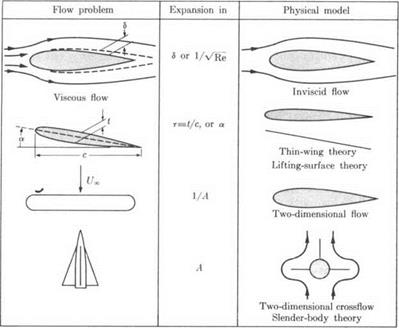
There are a variety of methods to obtain useful approximations. We shall discuss two different methods which are the ones mostly used in aerodynamic problems. One is the expansion in powers of a small parameter. Often the first term in this expansion may by itself be con­sidered as a physical model. Some of the expansions that will be discussed and the physical models derived in this manner are illustrated in Fig. 3-1.

A great majority of problems in fluid mechanics have been successfully attacked by series-expansion methods. The series obtained are usually only semiconvergent, i. e., asymptotic, and also frequently not uniformly valid. These features, which are closely associated with the so-called singu­lar perturbation nature of such problems, will be thoroughly discussed in the following section.

image63

Fig. 3-і. Use of series expansions for obtaining approximate solutions to aero­dynamic problems.

The second method of approximation that will be considered is the purely numerical one. In the future this will undoubtedly become of increasing importance as the full potentialities of modem computing devices are realized among aerodynamicists. There are many difficulties associated with numerical solutions. First of all, the equations for fluid flow are so complicated that no one has as yet succeeded in a step-by-step integra­tion of the full gas dynamic equations even assuming a perfect, inviscid gas. Therefore, the examples given will concern the numerical solution of linearized problems. Second, it is very hard to estimate the error induced by the approximation scheme employed. In contrast, this could in principle always be done in the analytical series solution by estimating the first neglected term. For this purpose, and for checking out the computational program, the analytical solutions for the limiting cases are extremely useful. Thus, far from making them obsolete, the new possi­bilities for numerical solutions give the analytical solutions extended practical usefulness.

Examples of Lifting Slender-Body Flow

A particularly fortunate consequence of the equivalence rule is that the outer flow is needed only for the calculation of g(x), which is a symmetric term that only influences the drag but not transverse forces and moments. For the calculation of lifting flows one therefore seeks the inner constant – density two-dimensional crossflow which is independent of the Mach number and which may be obtained, for example, by using complex variables. Some of the results of the classical two-dimensional theory may be directly applied. Thus, the flow around a circular cylinder applies to the lifting slender body of revolution, and the solution for a flat plate normal to the stream can be used for the flow around a thin, slender wing. A simple, yet practically useful configuration that incorporates these as special cases is that of a mid-winged body of revolution (see Fig. 6-3).

image89

Fig. 6-3. Wing-body configuration.


image90

To determine the perturbation velocity potential (</> = е2Фг2 in this case) it is, in this problem, convenient to align the x-axis with the body axis and let the free-stream vector be inclined by the angle a to the x-axis. That we then consider the flow in cross sections normal to the body axis instead of normal to the free stream will only introduce differences of order a2, which will be negligible in the present approximation; they will only be of importance for the calculation of higher-order terms. The prob­lem becomes that of finding a two-dimensional constant-density flow having a nondimensional vertical velocity of

W

= sin a ~ a (6-57)

U со

at infinity and zero normal velocity component at the body contour. Let the velocity potential corresponding to this flow be <p’:

tp’ = ip + az. (6-58)

We may obtain <p’ from a complex potential:

W'(X) = V'(y, z) + гф'(у, z), (6-59)

where

X = у + iz. (6-60)

The complex potential W’ will be constructed in steps using conformal transformation. First, the Joukowsky transformation

Хг = X + R2/X (6-61)

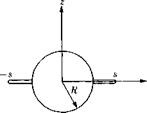
maps the outside of the contour onto the outside of a slit along the у i-axis (see Fig. 6-4) of width 2s i, where

image91

E2

Fig. 6-4. Mapping of wing-body cross section onto a slit.


Corresponding points are marked in the figure. A second transformation

X2 = (Xf – sf)112 (6-63)

transforms the horizontal slit to a vertical slit of width 2s i. Since in both transformations the plane remains undistorted at infinity, the flow in the X2-plane is simply

V?'(X2) = – iaX2, (6-64)

that is, an undisturbed vertical flow of (nondimensional) velocity a. By substituting (6-61)-(6-63) into (6-64) we obtain

Подпись:Подпись: 1/2Подпись: (6-66)image92"V?'(X)

Thus for the complex velocity perturbation potential,

W(X) = V?'(X) + iaX = – ia

This solution was given by Spreiter (1950). It is a straightforward process to derive from it the cases of body alone (R — s) and wing along (R = 0).

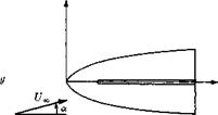
It is interesting to note that the crossflow considered above has no physical significance in a truly two-dimensional case, since then the flow will separate and the flow becomes rotational and nonpotential. In the slender-body case the axial flow keeps the crossflow from separating so that the potential-flow solution gives a realistic result. However, for large angles of attack the flow will separate, particularly when the aspect ratio is very small. The type of flow that then will be encountered is illustrated in Fig. 6-5. The flow separates at the leading edges and forms two station­ary, more-or-less concentrated vortices above the wing. Separation gives rise to an additional “drag” in the crossflow plane, which is equivalent to

image93

Fig. 6-5. Leading-edge separation on | j

image94a slender wing. T 1

increased lift and drag on the vehicle. Simplified models of this type of flow have been considered by, among others, Bollay (1937), Legendre (1952), and Mangier and Smith (1956).

The calculation of total lift and moments on slender bodies will be considered in Section 6-7.

Vortex Theorems for the Ideal Fluid

In connection with the study of wing wakes, separation, and related phenomena, it is of value to study the properties of the field vorticity vector f, (1-16). The reader is assumed to be familiar with ways of describ­ing the field of the velocity vector Q and with the concept of an instan­taneous pattern of streamlines, drawn at a given time, everywhere tangent to this vector. A related idea is the “stream tube, ” defined to be a bundle of streamlines sufficiently small that property variations across a normal section are negligible by comparison with variations along the length of the tube. Similar concepts can be defined for any other vector field, in particular the field of f. Thus one is led to the idea of a vortex line and a vortex tube, the arrows along such lines and tubes being directed according to the right-hand rule of spin of fluid particles.

Because f is the curl of another vector, the field of vortex lines has certain properties that not all vector fields possess. Two of these are identified by the first two vortex theorems of Helmholtz. Although these theorems will be stated for the vorticity field, they are purely geometrical in nature and are unrelated in any way to the physics or dynamics of the fluid, or even to the requirement of continuity of mass.

1. First Vortex Theorem. The circulation around a given vortex tube (“strength” of the vortex) is the same everywhere along its length.

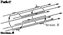
This result can be proved in a variety of ways, one simple approach being to apply Stokes’ theorem to a closed path in the surface of the vortex tube constructed as indicated in Fig. 1-4.

Fig. 1-4. Two cross sections of a vortex tube.

Подпись:We turn to (1-15) and choose for S the cylindrical surface lying in a wall of the tube. Obviously, no vortex lines cross S, so that
n • f = n • (V X Q) = 0. (1-23)

Hence the circulation Г around the whole of the curve C vanishes. By examining C, it is clear that

0 = Г= Гв~-Га + (two pieces which cancel each other). (1-24)

Hence Г л = Гд. Sections A and В can be chosen arbitrarily, however, so the circulation around the vortex is the same at all sections.

Incidentally, the circulation around the tube always equals JJn • f dS, where the integral is taken over any surface which cuts through the tube but does not intersect any other vortex lines. It can be concluded that this integral has the same value regardless of the orientation of the area used to cut through the tube. A physical interpretation is that the number of vortex lines which go to make up the tube, or bundle, is everywhere the same.

2. Second Vortex Theorem. A vortex tube can never end in the fluid, but must close onto itself, end at a boundary, or go to infinity.

Examples of the three kinds of behavior mentioned in this theorem are a smoke ring, a vortex bound to a two-dimensional airfoil spanning across from one wall to the other in a two-dimensional wind tunnel, and the downstream ends of horseshoe vortices representing the loading on a three­dimensional wing. This second theorem can be quite easily deduced from the continuity of circulation asserted by the first theorem; one simply notes that assuming an end for a vortex tube leads to a situation where the circulation is changing from one section to another along its length.

The first two vortex theorems are closely connected to the fact that the field of f is solenoidal, that is,

V • f = 0. (1-25)

When this result is inserted into Gauss’ theorem, (1-14), we see that just as many vortex lines must enter any closed surface as leave it.

There is a useful mathematical analogy between the f-field and that of the magnetic induction vector B. The latter satisfies one of the basic Maxwell equations,

V • В = 0. (1-26)

Although no such analogy generally exists with the fluid velocity vector field, it does so when the density is constant, which simplifies the continuity equation to

V • Q = 0. (1-27)

Hence, flow streamlines cannot end, and the volume flux through any section is the same as that through any other section at a given instant of time. One may examine in the same light the field of tubes of the vector pQ in a steady compressible flow.

Vortex Theorems for the Ideal Fluid Подпись: dQ dt Vortex Theorems for the Ideal Fluid

3. Third Vortex Theorem. We now proceed to derive the third vortex theorem, which is connected with the dynamical properties of the fluid. Following Milne-Thompson (1960, Section 3.53), we start from the vector identity

The second step is to take the curl of (1-28), noting that the curl of a gradient vanishes,

VXa=VX§ + 0- VX(QX?). (1-29)

ot

The operations Vx and d/dt can be interchanged, so that the first term on the right becomes df/cU. For any two vectors A and B,

V X (A X В) = (B • V)A – (A • V)B – B(V • A) + A(V ■ B). (1-30)

Hence

VX(QXf) = (T V)Q — (Q • V)r – f (V • Q) + 0. (1-31)

Substituting into (1-29), we have

V X a = ^ – a • V)Q + f(V ■ Q). (1-32)

Подпись: (1-33)

So far, our results are purely kinematical. We next introduce the con­servation of mass, (1-1), second line:

Подпись: (1-34)

whence, after a little manipulation, (1-32) may be made to read

Under the special conditions behind (1-11), a is the gradient of another vector and its curl vanishes. Thus for inviscid, barotropic fluid in a con­servative body force field, the foregoing result reduces to

This last is what is usually known as the third vortex theorem of Helm­holtz. In the continuum sense, it is an equation of conservation of angular momentum. If the specific entropy s is not uniform throughout the fluid, one can determine from a combination of dynamical and thermodynamic considerations that

V X a = V X (TVs). (1-36)

When inserted into (1-34), this demonstrates the role of entropy gradients in generating angular momentum, a result which is often associated with the name of Crocco.

Подпись: D_(t = D^(S Dt p) Dt2 Vp, Подпись: Dtn Подпись: (1-37)

To examine the implications of the third vortex theorem, we shall look at three special cases, in increasing order of complexity. First consider an initially irrotational flow, supposing that at all times previous to some given instant f = 0 for all fluid particles. In the absence of singularities or discontinuities, it is possible to write for this initial instant, using (1-35),

Since the quantity f/p is an analytic function of space and time, Taylor’s theorem shows that it vanishes at all subsequent instants of time. Hence, the vorticity vector itself is zero. We can state that an initially irrota­tional, inviscid, barotropic flow with a body force potential will remain irrotational. This result can also be proved by a combination of Kelvin’s and Stokes’ theorems, (1-12) and (1-15).

image10

Next examine a rotational but two-dimensional flow. Here the vorticity vector points in a direction normal to the planes of flow, but derivatives of the velocity Q in this direction must vanish. We therefore obtain

Once more, by Taylor’s theorem, f/p remains constant. This is equivalent to the statement that the angular momentum of a fluid particle of fixed mass about an axis through its own center of gravity remains independent of time. In incompressible liquid it reduces to the invariance of vorticity itself, following the fluid.

For our third example we turn to three-dimensional rotational flow. Let us consider an infinitesimal line element ds which moves with the fluid and which at some instant of time is parallel to the vector f/p. That is,

Подпись: dsimage11(1-39)

where e is a small scalar factor. Since the line element is attached to the fluid particles, the motion of one end relative to the other is determined by the difference in Q between these ends. Taking the ж-component, for instance,

In general,

§t (ds) = (ds • V)Q = e ^ • v) Q. (1-41)

Comparing this last result with the third vortex theorem, (1-35), we are led to

= 0, or e = const. (1-42)

It follows that (1-39) holds for all subsequent instants of time, and the vector f/p moves in the same way as the fluid particles do in three dimen­sions.

The proportionality of the length of a small fluid element to the quantity f/p can be interpreted in terms of conservation of angular momentum in the following way. As implied by (1-39), this length is directed along the axis of spin. Hence, if the length increases, the element itself will shrink in its lateral dimension, and its rate of spin must increase in order to con­serve angular momentum. To be precise, the quantity f/p is that which increases, because angular momentum is not directly proportional to angu­lar velocity for a variable density particle, but will decrease as the density increases, the density being a measure of how the mass of the fluid particle clusters about the spin axis.

For a constant-density fluid, of course, the vorticity itself is found to be proportional to the length of the fluid particle. In general, we can conclude that vortices are preserved as time passes, and that they cannot decay or disappear except through the action of viscosity or some other dissipative mechanism. Their persistence is revealed by many phenomena in the atmosphere. For example, one often sees the vortex wake, visualized through the mechanism of condensation trails, remaining for many miles after an airplane has passed.

As a final remark, we point out that in flows where only small disturb­ances from a fixed uniform stream condition occur, it can be proved that the vorticity f is preserved (to first order in the small perturbation) in the same way that it is in a constant-density fluid, since the effect of variations in density on the quantity f/p is of higher order.

Three-Dimensional Oscillating Wings

[1] See Notation List for meanings of symbols which are not defined locally in the text. In the following, D/Dt is the substantial derivative or rate of change following a fluid particle..

[2] It should be noted that more parameters are introduced when one takes account of the dependence on state of viscosity coefficient, conductivity, and specific heats.

[3] The bar over any symbol will be employed to designate a complex conjugate for the remainder of this chapter.

[4] For further details on this procedure, see Theodorsen (1931), Theodorsen and Garrick (1933), and Abbott, von Doenhoff, and Stivers (1945).

[5] See also Lagerstrom and Cole (1955) and Friedrichs (1953, 1954).

[6] An illuminating discussion appears in Section A.3 of Jones and Cohen (1960). See also the extended development in Chapter 10 of Liepmann and Roshko

[7] This scheme is associated with the names of Multhopp (1941) and Vandrey (1938).

[8] The Biplane. Let us consider two supersonic wings, with associated diaphragm regions, separated by a distance d in the f-direction (Fig. 11-7). Because there is a certain artificiality in the use of sources to represent the flow over the upper surface of each of these wings, some care must be

[9] These are bodies of similar shape, but stretched differently in the z-direction, or у-direction, or both. Thin airfoils of different thickness ratios constitute one class of affine bodies.

[10] This notation is commonly used in connection with mechanical or electrical vibrations and implies that the real (or imaginary) part of the right-hand side

. ft

must be taken in order to recover the physical quantity of interest. Here h is a complex function of position and allows for phase shifts between displacements of different points.

[11] If dimensionless x-variables are adopted in (13-28), based on reference length l = c/2, it is clear how the aforementioned к = шс/2С/„ will arise as one parameter of the problem.

The general planar wing problem, (13—16)—(13—17), has stimulated some imaginative research in applied mathematics. For M > 1, there are many analytical solutions appropriate to particular wing planform shapes, such as rectangular or delta, and all details have been worked through for elementary modes of vibration like plunging and pitching. Miles (1959) constitutes a compendium of such supersonic information, as does Landahl (1961) for the vicinity of M = 1. In the range 0 < M < 1 the only available exact linearized results pertain to the two-dimensional airfoil, whereas in constant-density fluid a complete and correct analysis has been published for a wing of circular planform.

Since the advent of high-speed computers, numerical methods have been elaborated to cover very general wing geometry and arbitrary con­tinuous deflection shapes. The approach for subsonic speed has been through superposition of acceleration-potential doublets, culminating in complete lifting surface theories which generalize the steady-flow results of Section 7-6. The definitive works are those of Watkins et al. (1955, 1959).

The influence-coefficient methods mentioned in Chapters 8 and 11 have proved adaptable to supersonic wings, although there are some details of the treatment of singularities that have apparently been resolved only very recently. Nonplanar wings and interfering systems represent an extension that is likely to be mechanized successfully within a short period of time.

Expansion in a Small Parameter; Singular Perturbation Problems

As will be seen, the majority of the problems that will be considered subsequently are characterized mathematically by the property that, in the limit as the small parameter vanishes, one or more highest-order – derivative terms in the governing differential equation drop out so that the differential equation degenerates. Hence not all of the original bound­ary conditions of the problem can be satisfied. This type of problem is known as a singular perturbation problem. In recent years a very powerful system­atic method to treat such problems has been developed by the Caltech school, primarily by Kaplun (1954, 1957) and Lagerstrom (1957).[5] The method is known by various names; the most frequently used one is “the inner and outer expansion method.” Another one is “the method of matched asymptotic expansions” suggested by Bretherton (1962). This name has been adopted in a recent book by Van Dyke (1964) and we will follow here his usage of terminology. The reader is referred to this book for more details on the method.

In order to introduce the method and its basic ideas we will first, as is customary in the literature on the subject [see, e. g.,

Erdelyi (1961)], consider a simple prob – Impulse I lem involving only an ordinary differen­tial equation. The problem chosen may be stated in physical terms as follows:

“Given a mass m on a spring of spring con­stant к with a viscous damper of damping

equation and the associated boundary conditions are

constant d. (See Fig. 3-2.) At time t = 0 the mass is given an impulse I (for example, by shooting off a charge to the left). What is the subsequent motion of the mass when tn is very small?”*

This problem will be solved in essentially three different ways. First, an exact solution may easily be obtained. The governing differential

This will be the reference solution used in assessing the approximate solutions that follow.

We shall now obtain an approximate solution valid for small mass m by use of simple physical reasoning. From the boundary condition (3-2) it follows that the initial velocity will be very high for small m, hence the dumping force will be the main decelerating force in the initial stages. The restoring force due to the spring, on the other hand, will be com­paratively much smaller because initially x is small. Therefore, the initial motion of the mass is governed approximately by the following equation:

Подпись: ^max Подпись: / d Подпись: (3-8)

The mass will have reached its maximum deviation when u(t) = 0. From (3-7) we thus obtain, approximately,

After the mass has reached its maximum deviation, the spring will force it relatively slowly back to its original position. Since the mass is so small, the motion will then be dominated by the spring and the damper. Conse­quently, the following equation will approximately describe its subsequent motion:

d ~ + kx = 0. (3-9)

This has the solution

x = Ae~ktld. (3-10)

In order to determine the integration constant A approximately, we notice that the initial phase of the motion as described by (3-6)-(3-8) takes place almost instantaneously for vanishing m. Therefore, it would appear to a slow observer as if at time t = 0+ the mass were suddenly displaced to xlnax and then released. Hence, the slow phase of the motion would approximately be described by (3-10) with A given by (3-8):

Подпись: (3-11)l_ —(kld)t de

We thus have arrived at two different approximate solutions. Integrating (3-6) with (3-2) and (3-3), we obtain

x ^ 2 [1 “ e~idlm)t], (3-12)

which is valid for small times and which will be called the inner solution and denoted by a superscript i. The approximation (3-11) valid for large times will be called the outer solution and denoted by superscript o. Thus

(3-13)

(3-14)

We shall now see how this basically intuitive method may be systema­tized to yield additional terms in a power series of an appropriate small dimensionless parameter. First, it is necessary to introduce dimensionless variables. A suitable set is

f = (3-15)

(3-16)

(3-24)

Obviously, this corresponds to the solution (3-10) for large times, the outer solution. The determination of the constant A% must wait for the moment.

The inner solution happens in a very short time. Therefore, in order to be able to study the solution with some resolution, we need to “magnify” the region of interest. This is achieved by stretching the independent variable. A suitable stretching is in the present example obtained by introducing for the inner solution x* = ж1 as a new independent variable

t = t*/e, (3-25)

which transforms the differential equation (3-17) and boundary conditions (3-18) and (3-19) into

Подпись: і a x ~w Подпись:Подпись: dtПодпись: Y + ЄЖПодпись:image64(3-26)

(3-27) (3-28)

Expansion in e, keeping l fixed, now gives the following inner expansion:

Expansion in a Small Parameter; Singular Perturbation Problems Подпись: (3-30) (3-31)

Xі = £ xi(t)en, (3-29)

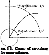
It is important to apply just the right amount of stretching in order to get a useful inner solution. In the present case we were guided by the physical insight into the problem which tells us that in the lowest-order term there should be a balance between inertia and damping terms, such as is retained in (3-30). If one applies too much stretching, for example, by setting instead of (3-25)

t = t*/e2, (3-32)

the features allowing one to match the inner and outer solutions (see below) would be lost. Thus with (3-32) the equation for the lowest-order term would be

j2 і

Подпись: = 0a xi

Подпись:~dF

with the solution

Xі ~ et.

In other words, the “magnification ratio” is so large that only the initial linear portion of the solution can be kept in view. This is illustrated in Fig. 3-3. The amount of stretching necessary for each problem is usually evident from the physics of the prob­lem; however, a check on this will al­ways be whether the expansion works.

The solution of (3-30) satisfying the boundary conditions (3-27) and (3-28) is

4=1- e~l, (3-33)

which is equivalent to (3-12).

To complete the zeroth-order solution it remains to determine the constant Aq in (3-24). Let us assume that the validity of the inner and outer solutions overlaps in some region of t* and that in this region we
can find a t* = 5(e) such that we have

lira 5 = 0 (3-34)

Подпись: and£-►0

lim (5/e) = a). (3-35)

£—►0

Such a choice would be, for example, 5 = Ve. Requiring the two expan­sions to overlap in the limit gives (since the inner solution is expressed as a function of I = t*/e)

lim [4(«/e)J = Hm [4(5)] (3-36)

£->0 £—>0

or

4(co) = 4(0). (3-37)

This is termed the limit matching principle which in words may be stated as follows:

The outer limit of the inner expansion = the inner limit of the outer expansion.

From (3-33) it follows that

4(oo) = 4° = і

and from (3-24)

£o(0) = 4* = -do-

4° = 4*,

A°0 = 1,

Подпись: gives Подпись: (3-38) (3-39)

Applying the limit matching principle,

which leads to an outer solution identical to the previous one obtained through intuitive reasoning.

Notice that the formal approach is nothing but a formalization of the intuitive one. However, the formal approach is capable of being extended to give higher-order terms to any order in e, which the intuitive one is not. First, we may construct a composite solution that is uniformly valid to order e over the whole region by setting

Подпись: (3-40)С О I г oi

x0 ~ xQ + x0 — x0 .

It is seen that this solution, in view of the matching, approaches the inner and outer solutions in the inner and outer regions, respectively, and carries over smoothly in between them. In the problem considered, the zeroth- order composite solution becomes

Подпись: (3-41)Подпись: Xo ~ e_ e~l = e~e – e~fh.

To proceed to the next higher approximation it follows from (3-23) and (3-24), (3-39) that the next term in the outer expansion is a solution

°f, о

Подпись:Подпись: Xidx і о – Є

dr

which has the general solution

Подпись:О — t* I AO—t*

X — —t 6 – p А.Є

Подпись:The first-order inner solution must, according to (3-31) and (3-33), satisfy

(3-44)

The general solution of this equation is

x = A+ Be-{ – l – le~l (3-45)

The constants A and B are to be determined such that the inner bound­ary conditions (3-27) and (3-28) are fulfilled. Since the lowest-order term has already taken care of these, x and its first derivative must both be zero. This gives

А І = – В І = 2, (3-46)

and hence

x = 2(1 – e~l) – 1(1 + e~l). (3-47)

The two-term inner expansion is thus

Xі ~ x’o + ехІ = 1 – e~{ + «[2(1 – e~l) – <(1 + e~f)] (3-48)

or, expressed in the outer (physical) variable

Xі ~ 1 – t* – (1 + <*)<r’*/e + 2e(l – e~l*u). (3-49)

The two-term outer solution is obtained from (3-24) and (3-41) to be

x° ~ x°o + ехІ = e~l — et*e~( + eAie~‘ (3-50)

The behavior of this near the inner limit may be obtained by series expan­sion in t*. The first terms in such an expression are

xoi ~ 1 – t* – e(t* – AT). (3-51)

In the inner expansion, on the other hand, the exponential term will be negligible in the outer limit and thus

It is evident from comparison of (3-50) and (3-52) that the two expressions match if

A“ = 2. (3-53)

The procedure may be formalized as follows: Express the n-term inner expansion in outer variables and take the те-term outer expansion of this. In our case take n = m = 2. Then the two-term outer expansion of the two-term inner expansion as obtained from (3-49) is

xio ~ 1 – t* + 2e. (3-54)

Next, express the two-term outer expansion in inner variables. This gives

/ = e~li – e2Ie~tl + eA'[e;-d. ■ (3-55)

Take the two-term expansion of this. This yields

xoi ~ 1 – it + tAl. (3-56)

Reexpress this in outer variables. Hence

xoi ~ 1 – t* + 6At (3-57)

Equating (3-57) and (3-54) gives A'{ = 2 as before. We have shown an application of the asymptotic matching principle of Kaplun and Lagerstrom (1957) which may be stated as follows (Van Dyke, 1964):

The m-term outer expansion of (the n-term inner expansion) = the n-term inner expansion of {the m-term outer expansion).

image66

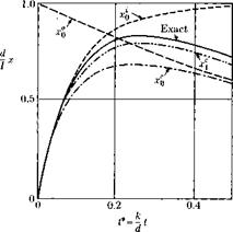
Fig. 3-4. Comparisons of various approximations for e = mk/d2 = 0.1.

This principle should hold for any combination of я and m, not only when they are equal as in the present case.

In the problems that will be treated in the following, mostly the limit matching principle will be used. We may now construct a composite expansion valid to first order by setting

жс ~ Xі + / – xio = (1 + 2e)(e~‘* – e~‘*le)

– + €c **). (3-58)

In Fig. 3-4 are shown the various approximate solutions for e = 0.1 together with the exact solution. As seen, the first-order composite solution gives a rather good approximation to the exact solution every­where, and the next term will probably account for practically all of the remaining difference.

We summarize now the main elements of the method:

(1) Writing the differential equations in a nondimensional form.

(2) Straightforward power series expansion of the differential equation and the associated boundary conditions using the physical variables. This gives the outer expansion.

(3) Suitable stretching of the independent variable to magnify the inner region sufficiently to be able to discern the details of the inner solution. Power series expansion of the solution in the small parameter keeping the stretched coordinate fixed gives the inner expansion.

(4) Matching the inner and outer expansions asymptotically.

(5) Constructing the composite expansion.

The method of matched asymptotic expansions has been used success­fully in a wide variety of fluid flow problems as well as in the theory of elasticity, and for some problems in rigid-body dynamics.

In the subsequent application of the method we will seldom proceed beyond the lowest-order approximation, in which case the limit matching principle usually suffices. Also composite expansions will only rarely be considered.