Category AERODYNAMICS

FAR FIELD CALCULATION OF INDUCED DRAG

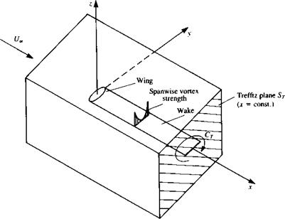
It is possible to compute the forces acting on a body or wing by applying the integral form of the momentum equation (Eq. (1.19)). For example, the wing shown in Fig. 8.29 is surrounded by a large control volume, and for an inviscid, steady-state flow without body forces, Eq. (1.19) reduces to

f P4(4 * n) dS = F — f pndS (8.143)

Js Js

where the second term in the right-hand side is the integral of the pressures. A

image323

FIGURE 8.29

Far-field control volume used for momentum balance.

coordinate system is selected such that the x axis is parallel to the free-streanj, velocity t/„ and the velocity vector, including the perturbation (и, v, и») becomes

q = (U«, + u, v, w) ]

If the x component of the force (drag) is to be computed then Eq. (8.143) becomes

D = — I p(U„ + «)[(!/« + u)dy dz + v dxdz 4- wdx dy — f pdydz The pressures are found by using Bernoulli’s equation:

p ~p«, = ^ Ul – ^ [(£/00 + и)2 + v2 + w2] = – puU„ ~^(u2 + v2 + w2) Substituting this result into the drag integral yields

D = — p I + u)dy dz — pf (U„ + u)(u dy dz + vdxdz + wdxdy)

+ pf uU„dy dz +^- f (и2 + v2 + w2) dy dz (8.144)

h 2 Js

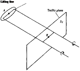
Note that the second integral will vanish due to the continuity equation for the perturbation, and the first and the third will cancel out. Now if the control volume is large then the perturbation velocity components will vanish everywhere but on the wake. If the flow is inviscid, then at this plane ST shown in Fig. 8.30 (called the Trefftz plane) the wake is parallel to the local free stream and will result in velocity components only in the у and z directions (thus u2«v2, w2). Therefore, the drag can be obtained by integrating the v

Подпись: Lifting line FIGURE 8.30

Trefftz plane used for the calculation of induced drag.

and w components on this plane only:

where Ф is the perturbation velocity potential. Use of the divergence theorem to transfer the surface integral into a line integral (similar to Eq. (1.20)) results

The third term in the first integral is canceled since in the two-dimensional Trefftz plane У2Ф = 0 and the integration is now limited to a path surrounding the wake (where a potential jump exists). If the wake is modeled by a vortex (or doublet) distribution parallel to the x axis, as in Fig. 8.30, the formulation of Section 3.14 for continuous singularity distributions can be used. Because of the symmetry of the induced velocity above and under the vortex sheet this integral can be reduced to a single spanwise line integral:

Подпись: (8.146)о fbwf2 p [bw/z

D = “ ДФи»гіу = — T(y)wdy 2 J-bj2 2 J~bwn

the minus sign is a result of the ЭФ/Эп direction pointing inside the circle of integration and bw is the local wake span. In Eq. (8.146) a “horse shoe” vortex structure is assumed for the lifting wing, but the wake span is allowed to be different from the wing’s span (e. g., due to self-induced wake displacement).

Following the same methodology, the lift force can be derived as

L = pU„ f^ ДФ dy = pU„[" Г(у) dy (8.147)

J-bJ2 J-bJ2

image325

The above drag formula may be useful in measuring the accuracy of data that is obtained by numerical integration of the local pressures. As an example for the use of Eq. (8.146), consider the elliptic lifting-line model of Section 8.1. The downwash at the lifting line (point A in Fig. 8.30) due to the elliptic load distribution is constant (Eq. (8.24)):

This was a result observed on the lifting line due to the semi-infinite trailing vortex lines. However, far downstream at a point В (in Fig. 8.30) the downwash is twice as much since to an observer at this point the vortex sheet seems to be infinite in both directions. Using the elliptic distribution Г(у) of Eq. (8.21) and by substituting w, into Eq. (8.146) the drag force becomes

P Cb>2 лЬ я

D = t" 2w, I T(y) dy = pw, — Гтах ~ рГтах 2 J-ы2 4 8

which is exactly the same result as in Eq. (8.27). Also, in this case a rigid wake

model is used and the wake span bw was assumed to be equal to the wing

span b.

Pressure and Force Information

The perturbation velocity field for the flow at angle of attack past a slender body of revolution is obtained by adding the results from Sections 8.3.1 and

8.3.2. The velocity field will be evaluated on the body surface for the determination of the forces and pitching moment.

For the axisymmetric problem of Section 8.3.1, the radial velocity component is given by the boundary condition (Eq. (8.108a)) as

qr = Q-R'(x) (8.127)

The axial component of velocity can be determined by taking the limit of Eq.

(8.117) as the radial coordinate approaches zero. Let us denote this component as

4x = Qxa (8.128)

It is given in Karamcheti15 (p. 577) as

qxA = 2^S”(x)ln^ + 4^ (s"'(x0)lnx-x0dx0 (8.128a)

The radial, tangential, and axial velocity components of the transverse problem of Section 8.3.2 are found by substituting r = R in Eqs. (8.124-8.126). The complete velocity distribution on the body surface is obtained by adding the free-stream components from Eq. (8.106) to the perturbation components to get

q(x, г, в) = (6« + qx, Q^a sin в + qr, Q^a cos в + qe) (8.129)

Подпись: Cp = l Подпись: 3L Qi Подпись: 4 Q. Pressure and Force Information Подпись: (8.130)

Substituting Eq. (8.129) into the pressure coefficient equation yields

It can be seen by an inspection of the velocity components that the magnitude of the squares of the crossflow plane components is comparable to the magnitude of the axial component itself and therefore the only term in the pressure coefficient equation that can be neglected is ql/Qi. The perturbation components from Eqs. (8.124-8.126) are substituted into the modified Eq. (8.130) and after some manipulation the pressure coefficient becomes

Cp = ~ (R’)2 ~ 4aR’ sin в + 0^(1 — 4 cos2 в) (8.131)

и*~(Т

Js Jo Jo

Подпись: F Подпись: pnR dddx Подпись: (8.132)

The force acting on the slender body is given by

where dx is the slender-body approximation for the length element. The slender-body approximation for the unit normal is

n = er – R ‘e, = — R ‘ex + cos 6ey + sin 6ez (8.133)

and substituting this into Eq. (8.133) yields the force components in the three coordinate directions:

Fx = f f R’RpdQdx Jo Jo

(8.134a)

ГІ ґ2 71

Fy = – Rp cos OdOdx Jo Jo

(8.1346)

Fz = — [ [ Rp sin в d6 dx Jo Jo

(8.134c)

The rate of change of the force components with respect

to x is given by

dFx С2л – r=-RR pde dx J0

(8.135a)

dF f2jT

-r2 = —R p cos в d6

dx J0

(8.1356)

dFz С2л

—— – – R psinddd

dx J0

(8.135c)

To use the pressure coefficient from Eq. (8.131) in Eqs. (8.135) the pressure is written as

P = kpQlCp + Pa,

(8.136)

image316,image317,image318,image319,image320,image321

where V is the body volume

8.3.1 Conclusions from Slender Body Theory

The above results for the aerodynamic forces acting on slender bodies show that for pointed bodies there is no lift and no drag force, but there is an
aerodynamic pitching moment. This important result is very useful when checking the accuracy of numerical methods that calculate the lift and drag by integrating the surface pressure over the body (and may result in lift and drag that are different from zero). Lift and drag forces are possible only when the base is not pointed, and a base pressure exists that is different from that predicted by potential flow theory (e. g., due to flow separations). Some methods for the treatment of bodies with blunt bases are presented by Nielsen.8,6

Transverse Flow Past a Slender Body of Revolution

The governing equation for the potential is Laplace’s equation (Eq. (8.105)),

Подпись: (8.105)Э2Ф З^Ф 1 ЭФ ЗРФ dx2 + dr2 + r dr + r2 d62

and the body boundary condition is given by Eq. (8.108b),

ЭФ

— (де, R, в) = – Q^a sin в (8.108b)

дт

The two-dimensional flow (in the y-z plane) of this problem resembles the flow past a cylinder, which was solved in Section 3.11. Therefore, the solution to this problem is modeled by a distribution of doublets of strength ju(jc) per length on the strip 0 s jt < /, z = 0. The doublet axes point in the negative z direction opposing the stream. The velocity potential and velocity components

are given by integration of the point elements (see Section 3.5) along the body’s length.

ф(г R – Ч_і_ Ґ /о 1104

Ф(Г’ в’Х)~ 4л l [(x – Xo)2 + r2f2 (8’118)

. ЗФ If’ (i(x„) sin edx0 З Ґ n(x0) sin в r2 dx0

qr{r, 0, x) – 3r – 4л. Jo [(jt _ Xo)2 + r2]3,2 4jr Jo [(jf _ Xo)2 + r2]5a

Подпись: (8.119) (8.120) (8.121) 1 ЭФ If’ m(x0) cos 0 dx0 ^(r, и, х)-гдв- 4л ^ [(je _ Xo)2 + r2]3/2

ЗФ -3 f’ ju(xo)(x – x0)r sin 0 dx0

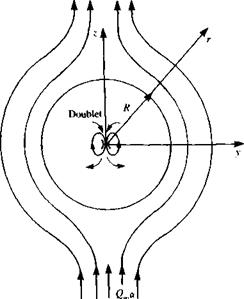
To satisfy the body boundary condition, consider the flow in the crossflow plane (as shown in Fig. 8.28). This is simply the flow past a circular cylinder and its radial velocity component from Section 3.11 is

ju(x) sin 0 2л R2(x)

Transverse Flow Past a Slender Body of Revolution Подпись: -Q.crsin 0

Thus the boundary condition at r — R becomes

image315FIGURE 8.28

Crossflow model using doublet distribu­tion along the x axis and pointing in the —z direction.

and the doublet strength is found to be

n(x) = 2nQ„aRx) = 2Q^aS(x) (8.122)

For small values of r (including the body surface) the solution is the flow past the circle in the crossflow plane and the perturbation potential and velocity components are

ф(г, в, x) – Q^ocR2

r

(8.123)

, . -7 sin в

qr{r, в, x) – Q*aR2 2 r

(8.124)

, „ . л cos в qe(r, 6, x) = Q^aR2 2 r

(8.125)

. . . ЭФ sin в

qx(r, e,x)~ -2Q„aRR

ox r

(8.126)

Note that since the doublet strength is a function of x, the streamwise (axial) velocity component is unequal to zero.

Axisymmetric Longitudinal Flow Past a Slender Body of Revolution

The axisymmetric version of Laplace’s equation (Eq. (8.105)) is

Подпись: (8.109)Э2 Ф Э2 Ф 1ЭФ dx2 + dr2 + r dr

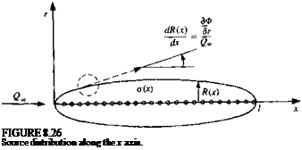
and the body boundary condition is given by Eq. (8.108a). The solution is modeled by a distribution of sources of strength o{x) per length along the body axis on the strip О^лг £/, z — 0 (Fig. 8.26) and the problem is essentially the axisymmetric version of the two-dimensional thin-airfoil thickness problem. The perturbation velocity potential and velocity components for this distribu­tion are obtained by integrating the equations of the point source (see Section 3.4) along the x axis:

= Ґ o(x0)dx 4л Jo V(* – Xq)2 + r2 ЭФ = J_ Ґ o(x0)rdx0 dr 4л Jo [(* – x0)2 + r2]3’2

(8.110)

(8.111)

Подпись: (8.112)ЭФ_ 1 Ґ o(x0)(x — x0) dx0 qAr, X) dx 4ло[{х-Хд )2 + г2]ш

To satisfy the body boundary condition (Eq. (8.108a)), which states that the flow is tangent to the surface,

^- = Rx) at r = R

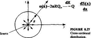
we use the slenderness arguments developed in slender wing theory and consider a mass balance in the crossflow plane (see Fig. 8.27). Surround the body axis with a circle of radius r and the volume flow (per unit length, Ax) through this circle is equal to the source strength

Подпись: FIGURE 8.26 Source distribution along the x axis.

o(x) = 2nrqr (8.113)

image314 Axisymmetric Longitudinal Flow Past a Slender Body of Revolution

If Eq. (8.113) is evaluated at r = R and the boundary condition of Eq. (8.108e) is used, the source strength is found to be

Axisymmetric Longitudinal Flow Past a Slender Body of Revolution Подпись: (8.115) (8.115) (8.117)

where S(x) is the body cross-sectional area. The potential and velocity components are then found by substituting o(x) into Eqs. (8.110-8.112),

Conclusions from Slender Wing Theory

The slender-wing solution presented here is based on the small-disturbance assumption, which automatically restricts the range of wing angle of attack. But in this particular case of slender wings, the incidence range is more limited than for high aspect ratio lifting wings because of flow separation along the leading edges. This effect will be discussed in Chapter 14, and in general, these leading-edge separated flow patterns will begin at angles of attack of 5-10° (depending on leading-edge radius).

The main importance of this slender wing theory is that it provides a three-dimensional solution for the limiting case of very small aspect ratio wings. These results can serve as test cases for more complex panel codes, within the limit of small incidence angles.

The slenderness assumption, where one coordinate is larger than the other two, allowed the local treatment of the two-dimensional crossflow. This logic can be carried over to more advanced methods and also for treating supersonic potential flows. This becomes clear when examining Eq. (4.73), where by omitting the jc-derivatives, the Mach number dependency is lost too.

The wake influence in this analysis was assumed to be small (negligible), which is, again, a good test case for more advanced panel codes.

8.3 SLENDER BODY THEORY

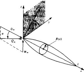
As a final example of classical small-disturbance theories, consider the flow past a slender body of revolution at a small angle of attack a, as shown in Fig.

8.25. It is convenient to use the cylindrical coordinates x, г, в and then the surface of the slender body of revolution is given as

Подпись: FIGURE 8.25 Nomenclature used for slender body theory.
image311

F = r~R(x) = 0 (8.103)

*(*)

/

Подпись: «1 Подпись: ar« 1 Conclusions from Slender Wing Theory Подпись: «1 Подпись: (8.104)

If the length of the body is /, slenderness means that the ratio of body radius R(x) to length is small and for small disturbances, the angle of attack a is small as well:

Подпись: V2<I> Подпись: Э2 Ф Э2Ф 1ЗФ 1 Эх2 + dr2 + r dr + г2 дв2 Подпись: (8.105)

Laplace’s equation for the perturbation potential (in cylindrical coordinates) is given by Eq. (1.33) as

where r = Vyi + z2.

In this coordinate system the free stream velocity is

Q«, = t/„e, + W»ez = Q»[cos a ex + sin ar(sin в er + cos в e0)]

« Qa°[ex + <*(sin в er + cos в ee)] (8.106)

Подпись: ЭФ л — + sin в - dr Подпись: for r = R(x) (8.107)
image312

Following the method of Section 4.2, the zero normal velocity component boundary condition on the body surface is УФ* • VF = 0, which yields

The small-disturbance version of this boundary condition is obtained after neglecting the smaller terms (according to Eq. 8.104):

дФ

— (*, R, в) = Q„R'(x) – Q„a sin в (8.108)

where R'(x) = dR(x)/dx and it is noted that the boundary condition has not been transferred to the body axis. The reason for this is that the velocity components of this flow are singular at the axis and the application of the boundary condition must be performed with care.

At this point it can be seen that the small-disturbance flow past a slender body of revolution at angle of attack can be replaced by two component flows, the axisymmetric flow past the body at zero angle of attack with body boundary condition

^(x, R, d) = Q„R'{x) (8.108a)

dr

and the flow normal to the body axis with free stream speed Qaa and body boundary condition

ЭФ

— (x, R, в) = -QooOr sin в (8.108b)

In the next two sections these two linear subproblems will be formulated and the complete solution is their sum.

The Method of R. T. Jones

The results of slender wing theory were obtained by R. T. Jones in a rather simple and elegant manner in 1945. Here we shall follow some of the basic ideas of his method.

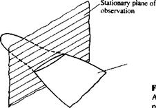
First, let’s examine the flowfleld due to a slender pointed wing in the crossflow plane (as shown in Fig. 8.22). This plane of observation is fixed to a nonmoving frame of reference, and as the wing moves across it, its momentary cross section increases. Since the flow is attached to the wing, the flowfield in

A slender wing moving across a stationary plane.

Подпись: Moving wing Подпись: FIGURE 8.22image306this two-dimensional observation plane is similar to the case of a flow normal to a flat plate (see Fig. 8.23). The velocity potential difference across the plate in this flow, as was shown earlier (Section 6.5.3) is

image307(8.99)

where b is the span of the plate and w is the normal velocity component (in this case w(x) = Qma(x)). However, this two-dimensional flow will not result in any forces because of the symmetry between the upper and lower streamlines. The only possibility to generate force, in this situation (with zero net circulation), is to create a change with time (e. g., due to the р(ЭФ/dt) term in the unsteady Bernoulli equation (Eq. (2.35))). Consequently, the R. T. Jones model suggests that the lift will be generated only if the fluid particles will be accelerated, relative to a “ground-fixed” observer.

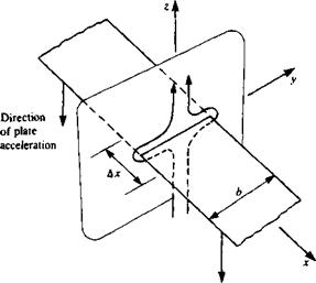
To demonstrate this principle, consider the two-dimensional plate of Fig. 8.24 as it is being accelerated downward (causing an upwash w>). The resulting force per unit length Ддс will be

image308A L d_

Ajc ^ dt

(8.100)

This result can be viewed as the “added mass” of the fluid that is being accelerated by the accelerating plate. Following Newton’s second law the force

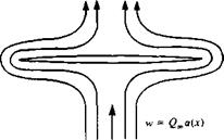
Подпись: FIGURE 8.23image309Schematic description of the crossflow streamlines.

Подпись: FIGURE 8.24 Two-dimensional flow resulting from the downward motion of a two-dimensional flat plate.
image310

due to accelerating fluid with added mass m’ by a massless plate is

AL djm’w)

Ax dt

and by comparing this formulation with Eq. (8.100) the added mass becomes

m’ = pb2^ (8.101)

which is equal to the mass of a fluid cylinder with a diameter of b.

Now, after establishing the added-mass approach, it is possible to follow the method of R. T. Jones for the slender pointed wing. The lift on the segment of the slender wing that is passing across the plane of observation in Fig. 8.22 will be due to accelerating the added mass of the fluid:

AL d(m’w) d(m’w)dx, , .dm’

where w(x) = £>.<*(*), —j~ is negligible, and dxldt = Q.

The Method of R. T. Jones

Ar~d,— – jTTrMx)-fr

This equation is equivalent to Eq. (8.89), and again states that there will be no lift if b(x) is constant with x.

To obtain the lift, drag, and pitching moment, this equation is integrated, to yield the same results as presented in the previous section.

Solution of the Flow Over Slender Pointed Wings

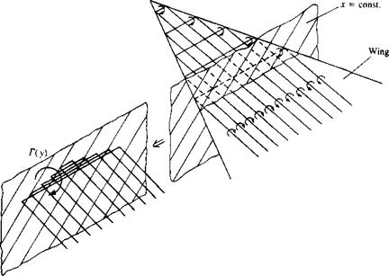
The integral equation (Eq. (8.68)) for the unknown doublet strength contains a strong singularity at у = y0 (see Appendix C for a discussion of the principal value of this integral). Recalling the results of Section 3.14 that a doublet distribution can be replaced by an equivalent vortex distribution [e. g., dii(y)/dy = — y(y)] allows us to use some of the results of thin-airfoil theory for the crossflow plane solution when the vortex distribution is used instead. The proposed vortex distribution consists of horseshoe type vortices distrib­uted continuously over the wing. This vortex model is described schematically in the right hand side of Fig. 8.17, where for the purpose of illustration,

Solution of the Flow Over Slender Pointed Wings

image293

FIGURE 8.17

Horseshoe model for the slender, thin, pointed wing.


x = const.


r(v)


-►

V


2


+A

2


FIGURE 8.18

Vortex distribution in the cross – flow (x = const.) plane.


Q^o(x)


discrete horseshoe elements are used instead of the continuous distribution. At any x — const, section the trailing vortices form a two-dimensional vortex distribution of circulation per length y(y) along the strip —b(x)/2<y < b(x)/2, z = 0 as shown in Fig. 8.18. Note that in the crossflow plane, owing to left/right symmetry, the total circulation is zero, and the lift is generated by the spanwise segments of the horseshoe vortices (as shown in the left hand side of Fig. 8.17). The perturbation velocity potential for this two-dimensional crossflow (modeled by the vortex distribution shown in Fig. 8.18, and formulated in Section 3.14) at any x station is


(8.69)


Observe that the positive vorticity vector in the y-z plane points in the positive x direction, as shown in Fig. 8.18. The velocity components in the x = const, plane, due to this velocity potential, are


(8.70)


(8.71)


Because of the slender wing assumption, only the local trailing vortex distribution (parallel to the x-axis) will affect the near-field downwash. By substituting this vortex distribution-induced downwash into the wing boundary condition, Eq. (8.63) becomes


(8.72)


Comparing this form of the boundary condition with the formulation for high aspect ratio wings (Eq. (8.11)) clearly indicates that due to the slender-wing assumption the effect of the spanwise vortices was neglected.

The solution for the vortex distribution, at each x station, is reduced now


image294image295image296image297

Solution of the Flow Over Slender Pointed Wings Подпись: (8.73)

to the solution of this equation for y(y) with the additional condition that

Подпись: Г(х,у)-Г(у) = Г„ Подпись: 1- Подпись: b(x)!2l J Подпись: (8.74)

Because of the similarity between this integral equation (Eq. (8.72)) and the lifting line equation (see Eqs. (8.10) and (8.11)), a solution of similar form is proposed. Let the spanwise circulation Г(х, у), at each x section, be an elliptic distribution as in Eq. (8.21):

The physical meaning of this circulation is best described by observing the horseshoe vortex structure shown in Fig. 8.17 where the downwash induced by the spanwise segments of the horseshoe vortices ahead of this x station is neglected when evaluating the boundary conditions. Then if the total circulation ahead of an x — const, chordwise station is replaced by a single spanwise vortex line, as shown in the left side of Fig. 8.17, then its strength will be Г(у).

Solution of the Flow Over Slender Pointed Wings Solution of the Flow Over Slender Pointed Wings

The spanwise distribution of the trailing vortices (shown in Fig. 8.18) is obtained by differentiating with respect to у (as in Eq. (8.41)):

Подпись: b(x)/2 Solution of the Flow Over Slender Pointed Wings Подпись: лЬ(х) Подпись: (8.77)

But this integral has already been evaluated in this chapter (see Eq. (8.22)) and resulted in a constant spanwise downwash. With the use of the results of Eqs. (8.22) and (8.24) the spanwise integration yields

Solution of the Flow Over Slender Pointed Wings Подпись: (8.78)

and Eq. (8.76) becomes

which shows that the spanwise induced downwash due to an elliptic circulation distribution is constant and independent of y. The value of Гтах is easily

Solution of the Flow Over Slender Pointed Wings Подпись: (8.79)

evaluated now and is

image298

To establish the relation between the velocity potential and Г consider a path of integration along the local у axis (for anr = const, section)

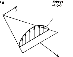
where the integration starts at the left leading edge of the x = const, station and the integration path is above (0+) or under (0-) the wing. Therefore, the potential jump (АФ) across the wing and the lift of the wing portion ahead of this x station (pQ<S(y)) are elliptic too:

ДФ(х = const.,у) = Ф(х, у, 0+) – Ф(дг, у, 0—) = 2Ф(х, у, 0+)

= Г(х = const., у) = Г(у) (8.80)

as shown in Fig. 8.19. Note that the local Г(у) is equivalent to the sum of all the spanwise bound vortex segments of the horseshoe elements ahead of it (see left side of Fig. 8.17) and therefore is equivalent to the lift of the wing portion ahead of this x station.

image299

By substituting y(y) and Гтах into Eqs. (8.69-8.71), the crossflow potential and its derivatives are obtained:

image301 Подпись: FIGURE 8.19 Elliptic spanwise loading of the slender thin wing.

This differentiation can be executed only if wing planform shape b(x) and

Подпись: ЭФ Y( V) v(x, у, 0±) = — (X, y, 0±) = = =F Подпись: (8.83)

angle of attack a(x) are known. The spanwise velocity component is

(Note that y(y) can be obtained as a solution of Eq. (8.72) directly from Eq.

(7.18) .) Based on Eqs. (8.71-8.72) the downwash on the wing is

ЭФ

w(x, y, 0±) = — (ж, y, 0±) = -0ooOr(x) (8.84)

dZ

The aerodynamic loads will be computed with the use of the linearized Bernoulli equation (Eq. (4.53)). The pressure jump across the wing is given by

Ap =p(x, y, 0—) — p(x, y, 0+) = pQ„ —АФ (8.85)

and this pressure difference

For example, let’s assume that the wing’s angle of attack is constant a(x) = a and for this case the pressure difference becomes

Подпись:Подпись: m 2 Ja / v P П2п b(x)db(x)/dx AP(x, y) = – Q*,a-

-y

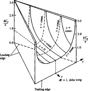
This spanwise pressure distribution is plotted in Fig. 8.20, and for a delta wing
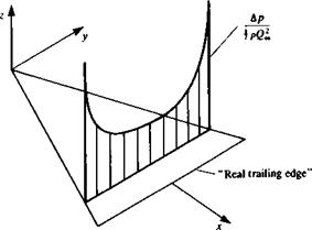
image302FIGURE 8.20

Spanwise pressure difference dis­tribution of the slender wing at an x = const, plane.

with straight leading edges, the pressure difference is plotted in Fig. 8.21. It is clear from these figures that this solution has an infinite suction peak along the wing leading edges. It seems as if the trailing edges of a high aspect ratio wing (while being swept backward) were folded into the root-chord and they are not visible, and consequently the lowest Ap at each x station is at the centerchord. Also since the trailing edge is not visible, the Kutta condition is not fulfilled along the “real trailing edge,’’ which resembles the side edges of this imaginary high aspect ratio wing.

The longitudinal wing loading is obtained by an integration of the spanwise pressure difference and with the use of the result of Eq. (8.25) that

Подпись: fb(x)l2 r '-Ь(х)П LПодпись: 1Подпись:image303

Подпись: FIGURE 8.21 Pressure difference distribution on a slender delta wing.
image304

(8.88)

Подпись: dL dx
Solution of the Flow Over Slender Pointed Wings Подпись: —b(x)/2 I Подпись: . 2-і 1/2 Подпись: (8.89)

With this in mind,

The interesting conclusion from this equation is that if there is no change either in or(;c) or in b(x), there will be no lift due to this section. Also for a wing with linear b(x) (delta wing) and constant a the longitudinal loading is linear too.

The lift of the wing from the tip to a section x is obtained by integrating dL/dx along x :

L(x) = J ^dx = ^pQl[a(x)b(x)2] (8.90)

This means that the lift of the wing up to a given x station depends on the local ct(x), b(x) and db(x)/dx only. For the complete wing, therefore, it is a function of its maximum span b and a (at this chordwise station):

L = ^pQlab2 (8-91)

When the wing extends behind its maximum span (and the slope db(x)/dx is negative) the contribution to the lift due to this portion is excluded by this model. Therefore, by using the maximum span in Eq. (8.91) the difficulties for wings having negative db(x)/dx near the trailing edge are avoided.

The spanwise loading, at any x station, is obtained in a similar manner:

fy – PCJW – 1 – } (8.92)

which is an elliptic spanwise load distribution, as shown in Fig. 8.19. The lift up to any section x can be obtained by the integration of the spanwise loading as well:

L(x) = f ^rdy = J Р£>1[Ф)Ь(х)2] (8-93)

J-b/2 dy 4

The lift coefficient is obtained by using Eq. (8.91),

„ жЪ2 л

CL = –a = – JRa (8.94)

and the induced drag coefficient (using Eq. (8.29)) for this elliptic distribution is

со=~2СІ = сЛ (8.95)

JT t) /

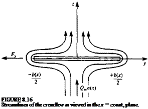
If the drag force is a result of the pressure distribution only then its magnitude is expected to be CLa, but this result of Eq. (8.95) indicates that the “leading-edge suction” is reducing the drag by 1/2. This can be shown by observing the suction force acting along the leading edges, as shown schematically in Fig. 8.16, which is a result of the rapid turning of the flow at
this point. The magnitude of this force was calculated in Section 6.5.3 (

(6.52) Подпись:) and is positive along the right leading edge,

,H*)

db(x) , ті r. – b2 a *

Подпись: -2 f Jo
Подпись: Fy-
Подпись: TC
Подпись: dx
Подпись: ■dx = - -jpQl 4
Подпись: a2(Cb(x) Jo

and negative along the left leading edge (here, for simplicity, a(x) = a w&§ assumed). Since this force acts on both leading edges of the wing, no net sideforce is created; however, these forces will have a forward-pointing component of magnitude Ts:

Consequently the drag force is the pressure difference integral La minus the leading edge thrust La/2 and is equal to only one-half of La, as obtained in Eq. (8.95).

The pitching moment about the apex of the wing is

M0= [ ^xdx = ?pQl( x-^-[a(x)b(x)2]dx (8.%)

Jo dx 4 Jq dx

Again, in order to evaluate this integral, the angle of attack and span variation with x are needed. As an example, consider a flat triangular delta wing with a constant angle of attack a where the trailing edge span is bT B :

b(x) = bT, e. – c

and by substituting this into Eq. (8.96),

Подпись: 2c _ 2c E — X,—Подпись: (8.97)Подпись: (8.98)M0 = jPQlJ0 X~ [a^b$.E]dx = ^pQlab? t.

and the center of pressure is at the center of area

Xcp_ 4/q_ 2

c Lc 3
Twisted Elliptic Wing

Twisted Elliptic Wing

The spanwise loading of wings can be varied by introducing twist to the wing planform. To illustrate the effects of twist, consider a wing with an elliptic chord distribution. For this purpose let us rearrange Eq. (8.44a) such that

This is the governing equation for the coefficients for the circulation distribution for the general case that is described using lifting-line theory. Section 8.1.4 presents an exact solution for an untwisted elliptic planform wing (elliptic loading) but solutions for other cases must be obtained numerically using techniques that will be described in later sections. It is of interest to study the effect of wing twist on the solution for a particular geometry (geometric twist occurs for a spanwise variation of angle of attack and aerodynamic twist occurs for a spanwise variation of the zero-lift angle).

Filotas81 has found a closed-form solution for a wing with an elliptic planform and arbitrary twist and that solution will be presented in what follows. Consider an elliptic chord distribution as given in Eq. (8.31):

Подпись: (8.59)с = c0 sin в

image286

and for simplicity let m0 = 2л. Then Eq. (8.58) becomes

Twisted Elliptic Wing

where the aspect ratio of the elliptic wing is Ж = 4b/nc0. Note that the above equation is a Fourier series representation for the right-hand side whose coefficients are given by

image287,image288

To find the wing lift coefficient, the coefficient Ax is obtained as

image289

and the lift is obtained by using Eq. (8.51):

Подпись: У Ы 2

Подпись: or(_y) = a ±a0 Подпись: = a±a0 |cos 0|

Example 1. As an example consider a wing with a linear twist where

The effect of the twist can be analyzed by taking the variable part of »(y) only, and adding the contribution of the constant angle of attack later. Therefore, let

ar(y) – a01 cos 0|

and by using Eq. (8.60) the coefficients A„ are computed as

A 4 1 Г*’2 2 1 C*’2

— = — — cos 0 sin 0 sin пв dd —————— ;—— I sin 20 sin n6dd

a0 лЖ/2 + nJo лЖ/2 + nJo

_2 1 Г sin (n – 2)0 sin (n + 2)01л’2

гЖ/2 + nl 2(n — 2) 2(n+2) J0

_ 1 1 Гsin (n — 2)л/2 sin (n + 2)лг/21

лЖ12 + п. (и — 2) (л + 2) J

Evaluating the individual coefficients for a wing with Ж = 6 and for a twist of a = ar0 |cos 0| and substituting into Eq. (8.42) yields

Г(0) = [1 sin 0 + xs sin 30 — sin 50 + ^5 sin 70 + • • •]

л

For a twist of a = ar0(— |cos 0|), the circulation is

Г(0) = 2bQ„a0 sin 0 _ x s;n 30 + ^ sin 50 – їв sin 70 + • ■ ■]

Я

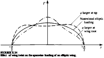
Подпись: FIGURE 8.14 Effect of wing twist on the spanwise loading of an elliptic wing.

These results, combined with an additional constant angle of attack a are plotted schematically in Fig. 8.14, which shows that having a larger angle of attack at the tip will increase the load there. Similarly, larger angles of attack near the wing root will increase the loading there.

8.1.6 Conclusions from Lifting-Line Theory

The most important result of the lifting-line theory is the ability to establish the effect of wing aspect ratio on the lift slope and induced drag. Some of the more important conclusions are:

1. The wing lift slope dCJda decreases as wing aspect ratio becomes smaller (as shown by Eq. (8.36) for an elliptic wing and by Eq. (8.57) for a wing with general span wise circulation).

2. The induced drag of a wing increases as wing aspect ratio decreases (as shown by Eq. (8.37) for an elliptic wing and by Eq. (8.53) for a wing with general spanwise circulation).

3. A wing with elliptic loading will have the lowest induced drag and the highest lift, as indicated by Eqs. (8.53) and (8.57).

4. This theory also provides valuable information about the wing’s spanwise loading, and about the existence of the trailing vortex wake.

5. The theory is limited to small disturbances and large aspect ratio and, also, Eq. (8.6), which requires that the wake be aligned with the local velocity, was not addressed at all (because of the small angle of attack, a, assumption).

6. There are possible modifications to this theory, such as the addition of wing sweep (e. g., Weissinger82). However, the study of wings with more complex geometry is difficult with this model, whereas some of the more refined methods (introduced in the following chapters) are clearly more capable in dealing with this problem.

7. Using the results of this theory we must remember that the drag of a wing includes the induced drag portion (predicted by this model) plus the viscous drag which must be taken into account.

8.2 SLENDER WING THEORY

In this chapter three-dimensional solutions that rely on the small-disturbance approximation are presented. By assuming that the wing is long and narrow (Ж« 1), and that its angle of attack is small, the special case of slender-wing theory can be developed.

8.2.1 Definition of the Problem

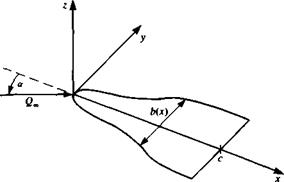
Consider the slender wing of Fig. 8.15 with a span b(x) and root chord c, where both the wing camberline rj and its angle of attack are small:

tan a « 1 and — « 1

c

and we consider wings with no spanwise camber (drf/dy= 0). The flow is

FIGURE 8.15

image291Nomenclature for a slender, thin, pointed wing.
assumed to be incompressible and irrotational and therefore the continuity

equation is

V2<t> = 0 (8.62)

with the boundary condition requiring no flow across the wing solid surface. This will be approximated at z = 0 for this case of small angle of attack and the 2 component of the total velocity w*(x, y, 0±) must be zero:

w*(x, y, 0±) = ^ (x, y, 0±) – = 0 (8.63)

In order to solve this problem, singularity elements that create antisymmetry (pressure jump) in the z direction are sought. The doublet solution based on the Э/dz derivative (see Eq. (3.36)) is the most suitable and it is developed for the general lifting surface in Section 4.5. By distributing these doublet elements over the surface of the wing, we obtain the following integral equation (Eq. (4.45)) for the boundary condition of zero normal flow:

J_ [ Фо, у0)[ (x-x0) 1 ,

4л Jwing+wake (y ~ To)2 L V(* – x0)2 + (y – To)2 + Z2 0 0

(8-64)

This integral is singular and its principal value must be evaluated, but before proceeding further, owing to the slender wing assumption some simplifications can be made. Since for the slender wing x»y, z we can assume that the derivatives are inversely affected:

Подпись: (8.65)э_ э_ _э

Эх ду ’ dz

Substituting this into the continuity equation (Eq. (8.62)) allows us to consider

Подпись: У2Ф Подпись: &Ф оРф л ду2 + dz2~° Подпись: (8.66)

the first term as negligible, compared to the other derivatives:

This can be interpreted such that the cross-flow effect is dominant, and for any x station, a local two-dimensional solution is sufficient. This is described schematically in Fig. 8.16. Also, for small-disturbance compressible flow (see Section 4.8), this implies that the Mach number dependency is lost and these solutions are applicable to supersonic potential flows as well.

Since the flowfield is now sought in the two-dimensional plane (jc = const.), the angle of attack and camber effects can be included in a local angle of attack <*(*) such that

, v dt}

the kernel in the integral of Eq. (8.64) becomes

(*-*o) 1 p

Подпись: for X >x0 for X < JC0 Подпись: (8.67)

Recalling the slenderness assumption that

Подпись: FIGURE 8.16 Streamlines of the crossflow as viewed in the x = const, plane.

The physical interpretation of this result is that portions of the wing ahead of a given * section (де > дс0) will have influence on the wing, whereas the influence of wing sections and the flow field behind this x section (x < x0) is negligible— thus the effect of the trailing wake for slender wings is small] By substituting this result into the boundary condition (Eq. (8.64)) and recalling that on the

Twisted Elliptic Wing Подпись: (8.68)

wing z = 0, Eq. (8.64) reduces to

which must be solved for any x = const, wing station with local span b(x). Note that by selecting the doublet distribution in the two-dimensional cross section, this boundary condition can be independently derived by integrating the two-dimensional doublet-induced velocity (Section 3.14).

General Spanwise Circulation Distribution

General Spanwise Circulation Distribution Подпись: (8.42)

A more general solution for the spanwise circulation Г(у) in Eq. (8.16) can be obtained by describing the unknown distribution in terms of a trigonometric expansion. Using the spanwise coordinate в, as defined in Eq. (8.23), the following Fourier expansion is selected:

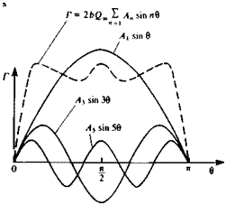
The shapes of the first three symmetric terms in this expansion are shown schematically in Fig. 8.13, and all terms fulfill Eq. (8.17) at the wing tips:

Подпись: (8.43)Г(0) = Г(л) = 0

image284

Substituting Г(0) and dT(0)/dy into Eq. (8.16) yields

FIGURE 8.13

Подпись: 5 Sine series representation of symmetric spanwise circulation distribution Г(0), n = l, 3. 5,….

By using Glauert’s integral (Eq. (5.22)) for the second term, this equation becomes

I, A• sin"e~ I, nA – s^j+a(e)~aUe)=0 (8’4*,)

General Spanwise Circulation Distribution Подпись: (8.45)

Comparing this result with Eq. (8.16) indicates that the first term is – ae and the second term is —at:

Therefore the section lift and drag coefficients can be readily obtained:

Подпись: 2 An sin пв sin kd Подпись: (8.46)Подпись:рЄооГ(в) 4 b

Cdl = C, a, = —— 2 A„ sin пв( 2 kAk S‘~- —) (8.47)

c(tf) „ = i ч=і sin в /

-Ы2 S

fba Cd(y)c(y) dy 2b2 Г ~ “

D, = —’—^——– = -^r 2 2 kAkAn sin кв sin nddd (8.49)

J-b/2 О О J0 л — 1 * = 1

Подпись: Ct Recall that General Spanwise Circulation Distribution Подпись: sin n0-sin ddd 2 Подпись: (8.48)

The wing aerodynamic coefficients are obtained by the spanwise integra­tion of these section coefficients:

Подпись: f 4) for n Ф к я/2 for n = к

and for the lift integral only the first term will appear. The lift coefficient becomes

jzb2A

CL = ——^ = jryRAj (8.51)

•З

For the drag, only the terms where n = к will be left:

jib2 °° °°

CD. = — 2 nA2n = лЖ 2 пА2„ (8.52)

^ Л=1 Л = 1

By using the results for the lift, this can be rewritten as

General Spanwise Circulation Distribution

General Spanwise Circulation Distribution

where <5і includes the higher-order terms for n = 2, 3, . . . (only the odd terms are considered for symmetric load distribution). This clearly indicates that for a given wing aspect ratio, the elliptic wing will have the lowest drag coefficient since <5i > 0 and 6, = 0 for the elliptic wing.

Similarly, the lift coefficient for the general spanwise loading can be formulated as

Подпись: (8.54)CL = лЖАх = m(ar – au)

Assume that the wing is untwisted and therefore a – aL0 = const. Following Glauert (Ref. 5.2, p. 142) we define an equivalent two-dimensional wing that has the same lift coefficient CL. This wing is now set at an angle of attack or* — aL{) such that

CL = 2л(а* — ar^) (8.55)

The difference between these two cases is due to the wake-induced angle of attack, which is obtained from these two equations

(a – aj – <«* – aj – CL[±- T] . Sl <1 + ад (8.56)

and

1 +

where 62>0. Taking Al from this relation and substituting into Eq. (8.51) results in

2л(а – azj
!+ —(! + 52)

Thus, for the elliptic wing 62 = 0 and also its lift coefficient is higher than for wings with other spanwise load distributions.

The Elliptic-Lift Distribution

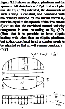
Подпись: Г(у) = Гтах Подпись: 1- Подпись: (8.21)
image265

The spanwise circulation distribution Г(у) for a given planform shape can be obtained by solving Eq. (8.16). In the particular case of an elliptic distribution of the circulation, the solution becomes rather simple since the downwash w, becomes constant along the wing span. Also, as will be shown later, wings having such a spanwise distribution will have minimum induced drag. The proposed distribution of Г(у) is shown in Fig. 8.6 and is

Подпись: dT(y) dy Подпись: 1 -
image267
image266 image268

This must be substituted into Eq. (8.16) so that the constant Гтах can be evaluated. For simplicity, let us first calculate the downwash integral (second term in Eq. (8.16)). The term dr(y)/dy is evaluated by differentiating Eq. (8.21):

The Elliptic-Lift Distribution Подпись: (8.22)
image269

and the downwash w, is obtained by substituting this result into Eq. (8.10):

Note that when у =y0, this integral is singular and therefore must be evaluated based on Cauchy’s principal value. It is possible to arrive at Glauert’s integral (Eq. (5.22)) by the transformation

b

У = 2 cos e

(8.23)

dy = —xsin в d6 2

(8.23а)

and at the wing tips у = – b/2, в = ж and at у — b/2, в = (8.21) to

0. This reduces Eq.

Г(0) = Гтах[1 – cos2 в)1’2 = Гтах sin в

(8.21а)

г!

Подпись: Ay)image270"FIGURE 8.6

v Elliptic spanwise distribution of the circulation Г(у).

св, г лЬ

L = pQj Г(у) dy = — pQ*. Г„ •’—6/2 ^

-2Г

-*’1 rr

Подпись: Another feature of the elliptic distribution is that the spanwise integral is simply half the area of an ellipse (with semi-axes Гтах and b/2) ,6/2 ] г (y)dy = n- J-bf2
Подпись: b _ лЬ 2 2~ТГтах
Подпись: Г 1 max
Подпись: (8.25)
Подпись: Consequently the lift and the drag of the wing can be evaluated: лЬ
Подпись: (8.26)
Подпись: сыг /Г  лЬ it A = PQocJ а{Г(у) dy = 0CjL = у Р(2-Гтах = - pT2ma% (8.27)
Подпись: -6/2 2bQr, The lift and drag coefficients become
Подпись: c^r CDi = T
Подпись: Itb r„
Подпись: pQlS 2 se. А п TLx 1 5
The Elliptic-Lift Distribution

Substituting Eq. (8.23) into Eq. (8.22) yields

Подпись:0°(“sin 0O) d6о

– (cos в – cos во)

The Elliptic-Lift Distribution

The principal value of this integral can be obtained by using the Glauert integral (Eq. (5.22)):

Г

1 max

Wi~-2b

(8.24)

Г

A max

a‘~2bQa

(8.24e)

angle of attack a(y) for the wing with the elliptic circulation distribution. If the chord c(y) has an elliptic form, too, the constant Гтах can be easily evaluated. Thus, assume

The Elliptic-Lift Distribution Подпись: (8.32)

where c0 is the root chord. Substituting Eq. (8.31) into Eq. (8.30) cancels the elliptic variation:

For an elliptic planform with constant airfoil shape, all terms but a(y) in this equation are constant, and therefore this wing with an elliptic planform and load distribution is untwisted (a(y) = a = const.). The value of Tmax is then

Подпись: (8.33)IbQJ^a – alJ 4 b

1 +—-

m0c0

The Elliptic-Lift Distribution Подпись: (8.34)

The area S of the elliptic wing is

Also, it is common to define the wing aspect ratio Ж as

image271(8.35)

Using the Ж and the area S for the elliptic wing and substituting into Eq.

(8.33)

The Elliptic-Lift Distribution The Elliptic-Lift Distribution Подпись: (8.33a)

, Гтах becomes

(<x – *L0) = CL'(a – au)

The Elliptic-Lift Distribution Подпись: (8.36)

With this expression for Гтах and using т0 = 2л, the lift coefficient (Eq. (8.28)) becomes

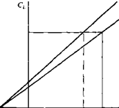
Here CL<x is the three-dimensional wing lift slope and the most important conclusion of this analysis is that this slope becomes less as the wing span becomes smaller due to the induced downwash. This is illustrated by Fig. 8.7, where for a wing with given aL0 the effective angle of attack is reduced by a,
according to Eq. (8.15). Consequently, for finite-span wings, more incidence is needed to achieve the same lift coefficient as the wing span decreases.

The induced drag coefficient is obtained by substituting Eq. (8.35) into

Подпись: Eq. (8.29),

image272(8.37)

which indicates that as the wing aspect ratio increases the induced drag becomes smaller. Also, the induced drag for the finite elliptic wing will increase with a rate of C as shown in Fig. 8.8.

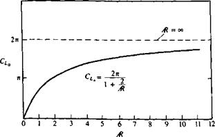
The lift slope CLa versus Ж for the elliptic wing (Eq. (8.36)) is shown in Fig. 8.9. The lift slope of a two-dimensional wing is the largest (2л) and as the wing span becomes smaller CLa decreases too.

The spanwise loading L'(y) (lift per unit span) of the elliptic wing is obtained by using the Kutta-Joukowski theorem:

image273

image275 image274 Подпись: Three-dimensional lift-slope
image276
Подпись: FIGURE 8.7 The reduction of lift slope for three-dimensional wings.

(8.38)

image277

CL FIGURE 8.8

Lift polar for an elliptic wing.

The Elliptic-Lift Distribution

image278

FIGURE 8.9

Variation of lift coefficient slope versus aspect ratio for thin elliptic wings.


Подпись:Подпись: QJ° - au,) Upwash FIGURE 8.10

Chord and load distribution for a thin elliptic wing. Note that the induced downwash is constant and combined with the downwash of the bound vortex is equal to the free-stream upwash, resulting in zero velocity normal to the wing surface (Eq. (8.7)).

The section lift coefficient Ct is defined by using the local chord from Eq. (8.31) and is

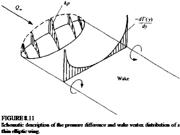
Подпись: FIGURE 8.11 Schematic description of the pressure difference and wake vortex distribution of a thin elliptic wing.
This spanwise wake vortex strength is shown schematically in Fig. 8.11. It is clear from this figure that near the wing tips, where dT(y)/dy is the largest, the wake vortex will be the strongest. Owing to the induced velocity at the wake it will roll up, mostly near the wing tips, to form two concentrated trailing

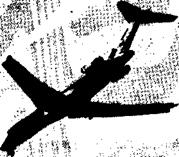
Flow visualization of the rollup of the trailing vortices behind an airplane (wing tip vortices made visible by ejecting smoke at the wing tips of a Boeing 727 airplane, Courtesy of NASA).

Подпись: FIGURE 8.12image282vortices as shown by the flow visualization in Fig. 8.12. The effect of this wake rollup on Г(у) is assumed to be negligible in this model; but this effect can be investigated by the numerical methods of later chapters.