Category BASIC AERODYNAMICS

Acceleration of a Fluid Particle: The Total Derivative

It is instructive to analyze the dynamics of fluid motion by means of differential elements rather than the somewhat mechanical procedure of converting the finite
Acceleration of a Fluid Particle: The Total Derivative

control-volume formulation into differential form. By this means, we can gain a deeper understanding of important features of the differential equations displayed in Table 3.6. We do this analysis in this subsection for the case of a two-dimensional flow in a rectangular coordinate grid to illustrate the procedure.

The Conservation of Momentum Principle is now applied to an infinitesimal system moving with the flow (i. e., to a fluid particle). For simplicity, the following derivation assumes an inviscid flow with negligible body-force effects. Details of the derivation are carried out in a two-dimensional Cartesian coordinate system for simplicity. The first step is to define a special way to look at the time derivative in a moving fluid, the so-called Eulerian, total, substantial, or substantive derivative. All of these terms are used interchangeably throughout the literature of fluid mechanics.

We illustrate the ideas by considering the time rate of change of the velocity (i. e., the acceleration) of a moving fluid particle. This special time rate of change is composed of the following two parts:

• unsteady acceleration: the rate of change due to changing conditions at a refer­ence point in the field.

• convective acceleration: the rate of change due to the motion of the particle as it passes through the reference point

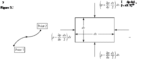
To illustrate these two different types of accelerations, imagine we are observers – moving with a fluid particle, as illustrated in Fig. 3.3.

Suppose that we reach a certain location (i. e., Point 1 in Fig. 3.3) in the flow at a certain time and at that same instant, the particle velocity changes because the flow is unsteady (i. e., the flow properties depend on time). This change in velocity represents acceleration of the particle. Now, what happens if the flow velocity is independent of time at a particular point? That is, any particle passing through that point always has the same velocity. Because the flow field is not necessarily uniform, then as the particle moves from Point 1 to Point 2, the moving observer notes that the velocity at Point 2 may be different from that experienced at Point 1 and that
this change in velocity has occurred over the transit time from Point 1 to Point 2. This corresponds to a change in velocity with respect to time (i. e., an apparent accel­eration) due to the motion (i. e., convection) of the particle through the flow—hence, the descriptive term convective acceleration introduced in the previous subsection. The total time rate of change of velocity of a fluid particle traveling through an unsteady flow field then consists of two parts: the local acceleration and the convec­tive acceleration. This combination often is referred to as the total derivative; other terminology also is used. With these physical ideas in mind, define:

DV

Eulerian derivative = total derivative = substantial derivative =——–

Dt

This notation represents the sum of both the unsteady (local) and the convective acceleration terms.

Recall that the velocity vector is a field property; it can be represented by a mathematical function of the spatial coordinates and time. That is, in general, the velocity vector can be written as V = V(x, y,z, t). For the two-dimensional case con­sidered here, we write V = V(x, y,t). Then, if two points, Point 1 and Point 2, are differ­ential distance Ar = Axi + Ayj apart in the x-y plane and At apart in time, we can write:

DV = lim J V(x + Ax, y + Ay, t + At)-V(x, y,t)l

Dt Atm0J At J

Use a Taylor series expansion to represent the first term in brackets. Notice that the partial derivatives of V in all three coordinate directions and time are required:

Подпись:, dV . dV dV A

Подпись: V(x,y,t) >.V (x, y, t) + —— Ax + —— Ay + —— At + dx dy dt

d2V (Ax)2
+ —–——+…

dx2 2 у

In the limit of a small time increment, the terms involving the squares (and higher) of the differential displacements become negligible. Then, passing to the limit as At ^ 0 gives:

DV = dV dx + dV dy +dV dy Dt dx dt dy dt dt dt’

Now, dx/dt = u because dx is the distance that the particle travels in the x-direction over the time interval dt. That is, dx is the x-projection of the infinitesimal distance between Point 1 and Point 2 that the particle traveled. Similarly, dy/dt = v. Thus, in this two-dimensional example:

DV _dV dV dV

Dt dt dx dy

Подпись: DV Dt Подпись: IT+(V-V)V- Подпись: (3.72)

In vector form, this equation may be written in shorthand notation as follows:

Подпись: DV Dt Acceleration of a Fluid Particle: The Total Derivative Подпись: (3.73)

Notice that this is precisely the representation for the rate of change of the velocity vector deduced in Eq. 3.66. Again, for emphasis, the first term represents the local acceleration and the second term is the convective acceleration. It must be empha­sized that the convective acceleration can be expressed in component form by direct substitution of the velocity vector in Eq. 3.72 only if rectangular coordinates are used. Thus, it is better to write:

which is valid for any curvilinear coordinate system.

It is now useful to use these ideas to check our derivation of the momentum equation. As before, the conservation of Momentum Principle can be expressed as Newton’s Second Law (i. e., sum of forces, ^f = time rate of change of momentum, pV) applied to a fluid particle (i. e., a system). Thus, the net force acting on the par­ticle (due to pressure only, by assumption) is equal to the product of the mass of the particle (a constant) and the acceleration of the particle—that is, the product of the mass of the particle and the time rate of change of the particle velocity.

The net pressure force on the particle may be derived by taking a snapshot of the moving particle at an instant of time. At the time the picture is taken, the par­ticle is assumed to be a cube (i. e., mathematically convenient; no loss of generality). Considering a two-dimensional Cartesian coordinate system, the cube appears as a square and the pressure force is pA, where the area is the length of a side times unity out of the page and the pressure acts perpendicular to all four sides. This is shown in Fig. 3.3(b).

Подпись: / Подпись: і + Подпись: d—dydx dy Подпись: j = F.
Подпись: dPdxdy dx
Подпись: V

The pressure is arbitrarily assumed to have the reference value p at the center of the particle—that is, at the point to which the element shrinks in the limit of a small mass element. With the positive coordinate directions assumed to be the positive force directions, the net pressure force, F, on the fluid particle is given by:

If there are no body forces or viscous forces, then, according to the Newton’s Second Law:

D DV DV

F = – (mt) = m— – ртМуНП—,

where the total acceleration can be represented by the total derivative, Eq. 3.72. Assembling all of the terms that enter into the momentum change/force balance,

F = P(dxdy)D,

it follows (for rectangular coordinates in two dimensions) that:

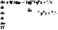
Эр. Эр. DV dV dV dV

-dx1 – dyJ=pD=P! T+pu aX+pv~dy •

Now, recall that V = ui + vj and write the two-component equations that follow from this vector equation; namely:

This is the momentum balance for a two-dimensional, inviscid, unsteady flow with no body forces written in Cartesian coordinate form. Compare Eq. 3.74 with Eq. 3.70, which originated in the statement of momentum conservation for a fixed con­trol volume. Because steady flow was assumed in Eq. 3.70, the time derivative terms are not present. It is clear, however, that the two methods of analysis yield identical results, as they must. Thus, starting with either a fixed control volume or an infini­tesimal fluid particle, the derivation of the differential equation expressing conser­vation of momentum leads to the same result. Note that although we illustrated the procedure in two dimensions, it is extended readily to three. The student is invited to repeat these steps for a three-dimensional element to verify that the method leads to the correct three-dimensional result (e. g., Eq. 3.69).

The other governing equations can be derived similarly. The differential – element technique is sometimes used to deduce the equations of motion in other than Cartesian coordinates by defining the appropriate infinitesimal element in terms of that coordinate system. For example, Fig. 3.4 shows an element that is appropriate for a three-dimensional cylindrical coordinate system. If the same pro­cedure used to determine the Cartesian momentum balance of Eq. 3.73 were used with this element, the equivalent of Eq. 3.71 would be found. The details are left for the student in an exercise at the end of the chapter. This method is more lengthy than the one used previously; that is, by direct use of the vector operations appro­priate to the coordinate system. However, it has the advantage of being more geo­metrically motivated and intuitive than the direct evaluation of the general vector expressions (e. g., Eq. 3.73) in dealing with other coordinate systems.

Differential-Continuity Equation

A derivation of the differential form of the continuity equation is carried out next. As explained, differential equations provide a tool for a more complete description of the flow field. In particular, a detailed description of the complete field behavior at any point in the flow then can be accomplished.

Recall from advanced calculus that a form of Green’s Theorem, the divergence theorem (also called Gauss’s Theorem), relates surface integrals to volume integrals —namely, if A is a vector, then:

j] (A ■ n)dS = JJJ (V • A)dE = JJJ divAdV. (3.47)

s v V

Differential-Continuity Equation Подпись: (3.48)

In what follows, we use the gradient-operator notation (V ^ gradient, V – ^ diver­gence, Vx ^ curl) instead of grad, div, and curl. Now, by identifying the vector A in Eq. 3.47 with the vector (pV) in Eq. 3.24, the surface integral in Eq. 3.24 may be changed to a volume integral by using the divergence theorem. Also, because the control volume that we are using is fixed in space, the limits on the volume integral in Eq. 3.24 do not vary with time. That being the case, the time derivative may be brought through the volume integral such that:

Подпись: fflff+V • (py) Подпись: dV = 0. Подпись: (3.49)

Then, using Eqs. 3.47 and 3.48 and putting both terms in Eq. 3.24 under the same volume integral:

Now, Eq. 3.49 must hold for any arbitrary control volume; therefore, the integrand must be zero. The integrand then represents the differential form of the continuity requirement.

The only way that Eq. 3.49 can be satisfied, then, is for the integrand to be zero. Thus,

Подпись: (3.50)dp+v • (pv) = o.

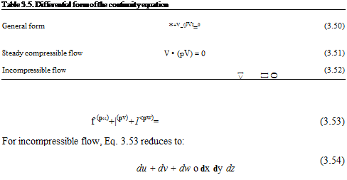
This is the general continuity equation in differential-equation form, valid at any field point in an unsteady compressible flow. Again, as in the control-volume conti­nuity formulation, there are special forms of Eq. 3.50 that fit cases of interest and simplify the equation. For steady compressible flow, for example, Eq. 3.50 becomes:

V • (pV) = 0.

For incompressible flow, Eq. 3.50 becomes:

V • V = 0,

which is valid for both steady and unsteady flow because in an incompressible flow, the density is constant and all of its derivatives therefore are zero. Table 3.5 summa­rizes the special cases of the continuity equation.

These differential equations can be written for any coordinate system by suit­ably expanding the vector operations. For example, in a three-dimensional Cartesian coordinate system with unit vectors i, j, and k in the coordinate directions x, y, and z and with the velocity vector having components V = ui + vj + wk, Eq. 3.50 becomes:

Подпись: Table 3.5. Differential form of the continuity equation General form *+V-(|JVI=0 (3.50) Steady compressible flow V • (pV) = 0 (3.51) Incompressible flow <1 II О (3.52) f (p“)+|(pv)+1<pw)= (3.53) For incompressible flow, Eq. 3.53 reduces to: du + dv + dw о dx dy dz (3.54)

The first of the conservation laws now is expressed in terms of both an inte­gral and a differential equation. The equivalent equations in other coordinates (e. g., cylindrical and spherical) are found by using the vector operators written in that system. For example, in three-dimensional cylindrical coordinates with unit vectors, er, ee, and ez, the velocity vector can be written as V = urer + ueee + uzez, and the divergence of the velocity vector is:

Подпись: V-„ 1 д. .1 due duz

V = – d-(rur) + ~~дЄе + ~дГ. r dr r r de dz

This expression is set to zero for continuity for an incompressible flow.

In the case of a compressible flow, the density multiplies each of the scalar velo­city components as before. It is important to understand the process described here, to apply the equations in the coordinate system that best fits the geometry of the problem to be solved.

example 3.8 Given: A velocity field for an incompressible flow is described by:

V = (2xy2) i + (2x2y) j.

Required: Determine if this flow field is physically possible.

Approach: To be physically possible, the flow field must satisfy the conservation

of mass.

Solution: Test the flow field by checking whether it satisfies the continuity equation for an incompressible flow, Eq. 3.13. Then,

du dv „2 „2 r

— + — = 2y2 + 2jt Ф 0,

dx dy

except at the origin. This flow field is not physically possible.

Appraisal: A flow field that is described as a given mathematical function or that is to be solved for any problem should always be checked to see whether it is physically possible—that is, whether it satisfies the continuity equation.

The Differential Form of the Momentum Equation

As in the case of the continuity equation, the starting point for the derivation of the differential form of the momentum equation is the integral form, Eq. 3.32:

d – JJJ p WE + || pV(V. n)dS = F = JJJ pbdV + JJ TdS. (3.55)

1 v S V S

The surface force is decomposed into two parts: one due to normal pressure force only, Tp; and the other containing both normal and shear components due to vis­cosity, tv, because there can be a viscous correction to the normal force due to the pressure. Thus, Eq. 3.55 becomes:

I JJJpVdV+Я pvV • ")dS=ffl pbdV+Л * pdS+JJ (356)

V S V s S

In following the same procedure used for the continuity equation, we must assemble all of the terms under a single-volume integral. Work with the force components first; the body-force term is already in the required form. Because Tp = – pndS, the surface integral can be converted from a surface to a volume integral by using the following form of the divergence theorem*:

JJ GndS = JJJVGdV. (3.57)

s V

where G is any scalar (e. g., p in the present case) and the gradient of a scalar is a vector. The second term on the right side of Eq. 3.56 then becomes:

JJt pdS = JJ-P«dS = – JJJVPdV’. (3.58)

S S v

* The derivation is shown here for convenience. Starting with the divergence theorem,

JJ (A n)dS = JJJ (V ■ A)dV.

S V

Put A = GB, where B = constant and G = scalar variable.

JJ^. ndS = JJJV (GB)dV,

S V

but V-(GB) = GV-B + B-VG = B-VG

JJ ^. nd^? = JJJb. VGdt>

Si V

B * JJ GndS = B * JJJVGdV^, because B = constant.

Si E

Thus, JJ GndS = JJJVGdK

S V2

The last term involving the viscous stresses may be rewritten in terms of a volume integral after first expressing tv in terms of its normal and tangential viscous stress components. Because details of the viscous-force modeling are the subject of Chapter 8, the volume integral corresponding to the viscous term is represented symbolically for the present as:

JM – Ш (3-59)

S V

and is carried along as a placeholder. Regardless of the details, this term is zero if the flow is assumed to be inviscid—a simplification of which we often take advantage.

Working with the first acceleration term on the left side of Eq. 3.56, the time derivative may be passed through the integral sign because the limits of integration are independent of time; the control volume is fixed. Thus,

fjJJp™"-JJJfw^- <3-60>

ut V i?

The second term on the left side:

convective acceleration – JJpV(V • n)dS, (3.61)

S

requires special consideration. We again attempt to convert the surface integral of Eq. 3.61 to a volume integral by means of the divergence theorem,

JJ(A. n)dS – JJJ(V. A)dV,

s V

where A is any vector. Notice that there is an apparent difficulty here in converting the surface integral to a volume integral by using the divergence theorem in this form because pV(V • n) in Eq. 3.61 is not of the form (A • n). In fact, pV(V • n) is a vector and (A • n) is a scalar. The divergence theorem is not directly applicable to the conversion of Eq. 3.61 into a volume integral. Notice, however, that the problem is circumvented if we focus on any one scalar component of the velocity vector V. Then, the procedure we follow is to work first with one component and then gener­alize the results to full vector form.

For simplicity, use Cartesian coordinates and focus on the x-component, u, of the velocity vector:

V = ui + vj + wk. (3.62)

Then, the x-component of the vector surface integral in Eq. 3.61 is converted readily to a volume integral by means of the divergence theorem. We find:

JJ pu(V ■ n) dS = JJJ V (puV)dV

S V

Inserting this and the x-components of the other terms into Eq. 3.56:

Jfl|(Pu)dV + JJJV (PuV)dV – i. JJJpbdV-lllVPW +JJJ t. dV,

V v L V v v _

Подпись: i.

Подпись: JJJ-j^T(Pu) + V (pиУ)-
Подпись: (pb -Vp + ^ )!> dV = 0

where the x-components of the vectors on the right side are found by dotting with the unit vector, i. Collecting all of the terms under the same volume integral results in:

Thus, for an arbitrary control volume, we require that the integrand vanishes with the result that for the x-component,

I(pu) + V (puV)-i.(pb-Vp + ^) = 0. (3.63)

This is the so-called conservation form of the differential-momentum equation (x-component). It is clear that the other two components can be found by a similar analysis. The three momentum-equation components are used commonly in conser­vation form to set up numerical solutions in computational fluid dynamics (CFD) procedures, discussed later in the book.

It is useful to expand the first term,

Э, . du dp

st(p u)=p¥+u 17 •

and the second term by means of the vector identity V^A) = A • Vф + фV• A. Then,

V • (puV) = pV • Vu + uV • (pV).

The combination of the first and second terms yields:

d(pu) + V – (puV) = p^u + u^r + pV – Vu + uV. (pV) = dt dt dt

Подпись:Подпись: = pПодпись: f+V-^)Подпись: =pdu „

— + V ■ Vu

dt where the part multiplied by u is the continuity equation and must be set to zero so that mass is conserved. Noting that the pressure gradient in Cartesian form is:

Подпись: (3.64)„ 3p. 3p . dp,

Vp=¥i +3pJ +¥ k

Подпись: p Differential-Continuity Equation Подпись: (3.65)

we can write the momentum equation in Cartesian component form as:

This suggests that in compact vector form, the differential-momentum equation is:

Подпись: (3.66)Г 3v ^

pl^V + V-VVj = – Vp + pb + fv,

which is sometimes called the primitive-variable form of the momentum equation. In effect, we split off the continuity equation from the conservation form (i. e., Eq. 3.63
and the other two components) to arrive at the primitive form. Expressed in words, this equation states that “the mass per unit volume times the total acceleration equals the force per unit volume” at any point in the field of motion. In the usual particle-mechanics problem, the time derivative of the velocity vector is the accel­eration. Because of our use of Eulerian-field point of view, the derivative of V is the local acceleration term; the second term, V • VV, is the convective acceleration term that corrects for the rate of change of fluid properties due to motion in the field.

Although the derivation was carried out for Cartesian coordinates, Eq. 3.66 is the correct result for any coordinate system provided that we properly define the convective accleration V • VV and correctly interpret the implied mathematics. Note that unlike the Cartesian scalar-component form in Eq. 3.65, this term cannot be interpreted as simply V dotted with the gradient of V (the gradient of a vector is not defined!). A careful discussion and interpretation of this seemingly pathological term is required. Many errors in the application of the differential-momentum equation can be traced to an insufficient understanding of this term and its exten­sion to other than simple rectangular Cartesian coordinate systems. Observe also that this term is nonlinear. That is, it involves products of the velocity components whereas, for comparison, the local acceleration term is linear in the sense that it con­tains no products (or transcendental functions) of the variables.

The operator V • V is sometimes called the convective operator. In Cartesian form, it is correct to interpret this as an operator:

„ d d d V • V = u— + v— + w— dx dy dz

and then apply it to each scalar component of the vector on which it acts. For example, for the x-component of Eq. 3.65, we find that taking the dot product of the velocity vector with the gradient of u:

Подпись: V. Vu = V-du. du. du, 1 du du du —i + —j + — k = u — + v — + w —

dx dy dz J dx dy dz

Differential-Continuity Equation Подпись: du du du (U) = u— + v — + w —. dx dy dz

is the same result found by treating V V as an operator acting on u; thus,

The convective element of the momentum balance must be treated with great care. It is best to treat the form, V • V, as a shorthand notation that can be evaluated cor­rectly and explicitly as demonstrated for Cartesian coordinates. To find the correct form for any coordinate system, it is necessary to use vector analysis.[9] The form that is correct in any coordinate system is:

Подпись: (V-V)V = V Подпись: Vx VxV. Подпись: (3.67)
Подпись: 2

Then, whenever it is necessary to write the momentum equation for cylindrical or spherical coordinates, we use Eq. 3.67 to arrive at the correct equations. This expression is demonstrated herein when we evaluate the momentum equation in component form for cylindrical coordinates (see Eq. 3.71). As is typical, mathemat­ical results such as Eq. 3.67 often have important physical implications. For example, the first term contains the square of the local flow speed, which suggests a connection to the kinetic energy of the flow. The second term involves the curl of the velocity vector, V x V, which is associated in subsequent chapters with important properties of the flow field, such as rotation and vorticity.

Now that the general form for the momentum balance, Eq. 3.66, is deduced, we can proceed as usual to write reduced forms that suit situations of special interest. In the complete form, the viscous-force term, fv, is replaced by a suitable model that relates the components of the viscous force to the geometry of the flow. The Newtonian model for viscous force introduced in Chapter 2 (see Eq. 2.4) is general­ized in Chapter 8 for this purpose. The resulting equation (or equations, if written in component form) is called the Navier-Stokes Equation after Navier (French) and Stokes (English), who developed the equations independently in the mid-1800s. Famous names are associated with other special forms of the momentum balance. For example, an important case is Euler’s equations, in which the viscous forces are dropped. The inviscid approximation has many applications in aerodynamics problems. Table 3.6 summarizes important special forms of the differential – momentum equation.

The second set of equations (Eq. 3.68) in Table 3.6 represents the Cartesian form of the Navier-Stokes equations for an incompressible fluid with a Newtonian model for the viscous forces. The viscosity coefficient, p, is assumed to be constant (see Chapter 2). The details of the viscous model used here are elaborated on in Chapter 8. Notice that in the other cases shown in the table, there is no assumption of incompressibility. Equations 3.69-3.71 are valid for compressible flow because after splitting the continuity equation off of the original momentum balance, there are no derivatives of the density remaining in the general equation. However, if vis­cous forces are retained, density gradients may have important consequences.

Equation 3.70, the two-dimensional Euler’s equations for Cartesian coordinates, is used frequently and should be compared to the set shown in Eq. 3.71 in Table 3.6, written in polar coordinates. Students should test their understanding of these results by reducing the complete vector-momentum equation (Eq. 3.66) to the special cases shown in the table. It is important to see that treatment of the convective acceleration by using the V* V operator approach (correct only for the Cartesian case) does not work for cylindrical coordinates. It is necessary to use the full form of the convective accleration in vector form (Eq. 3.67) to derive the result shown in Eq. 3.71.

Because the momentum equation is a vector equation, the result is that three more of the required six equations needed for the general fluid-mechanics problem now are established. If the flow is assumed to be incompressible, then the continuity and momentum equations are sufficient to define the problem. This simplification is used to advantage in subsequent chapters.

Differential-Continuity Equation
Подпись: (3.69)
Подпись: (3.68)

example 3.9 Given: Consider the following flow field. It is steady and inviscid with no body forces. The flow field is described by V = (2x)i + (3x-2y)j. Assume the density (constant) to be p = 0.2 slug/ft3.

Required: Find the pressure gradient in this flow field in the x-direction at a cer­tain point specified by (x = 3, y = 2).

Approach: Because the x-component of the pressure gradient (i. e., dp/dx) is required, use the x-component of the differential-momentum equation (Eq. 3.70) with constant density.

Solution: First, is this flow physically possible? Check using Eq. 3.52: Yes (verify this). Next, substitute Eq. 3.70 and evaluate:

u ^ + v ^ = 4x + 0 = _1 dp, and solving, dp = _2.4 lbf/ft2/ ft. dx dy p dx dx

Appraisal: For this particular flow field, the pressure gradient in the x-direction is independent of y. This, of course, is not a general result. Note that this example does not represent a solution of the differential-momentum equation but rather is an exercise in applying the equation.

EXAMPLE 3.10 Required: Derive Euler’s equation in two-dimensional polar coordinates by direct evaluation of the general momentum equation (Eq. 3.66) and Eq. 3.67.

Approach: Assume steady, inviscid flow without body forces and insert Eq. 3.67 for the convective acceleration so that the momentum equation is valid for any coordinate system. Then, use the vector expressions for the gradient and curl in polar coordinates.

Physical Laws in Differential-Equation Form

In examining the example problems describing the application of the physical laws in control-volume form, notice that evaluation of the surface and volume integrals often involve assuming average values of the variables. For example, averaged den­sities, velocities, and pressures were used to make the integrals tractable. That is, there was no detailed information on the actual point-to-point variations in any of the key variables. Clearly, in some situations, this would be a crude description of the fluid motion. It might be required, for example, to know how the pressure is distrib­uted over the surface or how the velocity is distributed through a viscous boundary layer. In determining the forces on a wing, it is required to know not merely the mag­nitude of the lift and drag forces but also how they are distributed over the surface. Problems of this type require a sharper mathematical representation of the physical laws. This precision is available only if we convert the equations of fluid motion into differential form. Then, by solving the resulting set of differential field equations, we can determine in detail the behavior of the flow variables throughout the domain of the problem. In real problem solving, both the control volume and the differential – equation formulations often are used together to generate the required information.

The differential equations describing fluid flow can be derived directly by analysis of differential-control volumes. In this method, we define small control vol­umes that conform to the type of coordinate system to be used. For example, in Cartesian coordinates, a differential cube is appropriate. The procedure is repeated for each coordinate system of interest. However, a simpler way is to work from the control-volume formulation already worked out herein. This method involves con­verting all surface integrals and other terms into equivalent volume integrals by means of appropriate forms of Green’s Theorem. Then, all terms are collected into a single-volume integral, which is equal to zero. Because the control volume is of arbi­trary size and shape, a necessary condition for satisfaction of the resulting equation is that the integrand must be zero. The result is the required differential form of the original integral equation, which can be expressed in any desired coordinate system by knowing the vector operators such as the gradient, divergence, and curl in that coordinate system. This procedure is followed for each of the basic physical laws.

The Energy Equation in Control-Volume Form

The energy equation represents the fifth of the required six equations needed for the solution of the basic aerodynamics problem defined in the chapter introduc­tion. Specifically, it must be included in any consideration of compressible flow. The energy equation in aerodynamics is a statement of the First Law of Thermo­dynamics. The rate form of the First Law already was reduced to control-volume form in Eq. 3.22. Thus, for conservation of energy, we require that:

dr=f 0№ + Яe i-V =Q-W, (3-39)

where Q and W are the rates of heat flow and work flow from the surroundings. Only a brief discussion of the energy equation is needed here because most aspects are covered in the basic physics or thermodynamics already studied. Emphasis is on the forms needed and the notation used in compressible-flow aerodynamics.

As shown in Eq. 3.32, the rate of change of the total energy of the system of particles (expressed in control-volume form) consists of two terms: (1) the rate of change of the energy contained instantaneously within the control volume, and (2) the passage of energy through the surface of the control volume by convection with the flow.

The intensive energy variable e’, shown in the integrals in Eq. 3.39, is used to represent all forms of energy that might be resident in the fluid. It consists of several parts that must be distinguished in solving compressible-flow problems. Any differ­ential mass element in the control volume simultaneously may carry kinetic energy due to both the random motion of the molecules that comprise the element and the organized motion of the fluid. In general, there also may be potential energy due to the changing position in a body-force field (we use a uniform gravity field to illus­trate). Thus, the energy, e’, per unit mass often is defined in fluid-mechanics problems to consist of the following three terms:

V 2

e’ = e + — + gz, (3.40)

where e is defined as the internal kinetic energy (due to random microscopic mol­ecular motion); V2/2 is the directed kinetic energy per unit mass (with V as the mag­nitude of the velocity vector, a function of position and time in the field); and gz is the potential energy due to a uniform gravity field (assumed to act in the ver­tical direction—i. e., the z-direction in three-dimensional space). z is assumed to be measured from a convenient datum plane such as the earth’s surface. This notation is chosen to conform to that used most often in textbooks and other publications describing compressible-fluid flows.

To complete the statement of the First Law of Thermodynamics, we must provide models for the heat transfer to the control volume and the rate of work done by the control volume on the surroundings as indicated by the terms to the right of Eq. 3.39. Heat transfer may occur in the following two ways:

• internal heat release within the control volume such as by combustion, QINT

• heat transfer by conduction across the surface of the control volume, represented in terms of local conditions as:

Qcond = Я ¥S, (3-41)

S

where Q is the heat-transfer rate across the surface per unit surface area and Qcond is defined as the total heat-transfer rate to the control volume due to conduction from the surroundings. Heat transfer by radiation is not considered here, but it may be of crucial importance in problems in which temperatures are high (e. g., in the flow around a spacecraft reentering the earth’s atmosphere). Transfer of energy by convection across the boundaries of the control volume was accounted for in the surface integral (i. e., the third term in Eq. 3.39).

It remains to provide models for the rate of work done by the control volume on the surroundings. This work rate may arise from the following three sources:

1. Machine work (sometimes called “shaft work”) done internally within the control volume but carried by mechanical linkage through the control surface (e. g., a turbine or compressor connected to an external device by a rotating shaft). Let WM denote the mechanical work rate done by the fluid inside the control volume, where the dot over the “ W” denotes “time rate of change.” WM traditionally is assumed to be positive when it represents work done on the surroundings. Hence, it appears in the energy equation with a negative sign, as shown on the right side of Eq. 3.39.

2. The rate of work done at the control surface due to surface stresses, which has two parts. The part due to stresses tangent to the surface usually are due to the effects of viscosity. We denote the viscous-work-rate term by the symbol WY, which represents the work rate done on the fluid within the control volume by viscous forces acting at its bounding surface. The second part is due to the normal stresses, usually related to the pressure forces. Multiplying the pressure force on the surface per unit area, – pn, by an infinitesimal surface area, dS, yields a force that may be represented as a vector everywhere perpendicular to the control surface by multiplying this force by the outward pointing unit normal vector—namely, – pndS. Recall that force times distance in the same direction equals work. The work rate, then, is the force times the rate of change of dis­tance in the same direction—that is, the force times the velocity component in the direction of the force (the convenience of using a “rate” equation is evident here). However, because – pndS is a vector, taking the dot product of V with this vector results in multiplying the pressure force by the component of the velocity vector in the direction of this force. Thus, – p(V • n)dS is the required work rate due to normal pressure acting at the control surface. Then, the total work rate done on the system by normal surface tractions is given by:

-ДО p(V*n)dS.

S

3. The rate of work done on the fluid within the control volume by body forces. This term may be represented by:

jjj (pMV). V,

where b is the body force per unit mass and the dot product with the velocity vector yields the rate of work.

The Energy Equation in Control-Volume Form Подпись: (3.42)

Assembling all of these terms and dropping the potential energy term (negli­gible in most aerodynamic problems) gives the general energy equation, Eq. 3.42:

The Energy Equation in Control-Volume Form Подпись: (3.43)

Equation 3.42 may be expressed in a simpler form that is valid for a large class of aerodynamics problems by restricting the range of interest to steady flows with negligible viscous work, no combustion, negligible body-force effect, and negligible changes in potential energy. Then, the preceding equation simplifies to:

The various special forms of the energy equation that we use are summarized in Table 3.4.

The Energy Equation in Control-Volume Form The Energy Equation in Control-Volume Form The Energy Equation in Control-Volume Form

Table 3.4. Energy equation in control-volume form

Now, recall that the thermodynamic state variable enthalpy, h, is defined by h = e + р/р, so that this equation becomes:

The Energy Equation in Control-Volume Form(3.44)

Подпись: COND The Energy Equation in Control-Volume Form

Defining the stagnation enthalpy as h0 = h + V/2, Eq. 3.44 may be written as:

For an ideal gas, the internal energy is proportional to the (absolute) tempera­ture. Therefore, we write e = cvT, where cv is the specific heat at constant volume. Also, remembering from the equation of state that the ratio р/р = RT, then h is also proportional to the temperature. Thus, it is typical to write h = cp T, where cp is the specific heat at constant pressure. In many situations, it is possible to assume that the two specific heats are constants independent of the temperature. We then speak of a calorically perfect gas. There exist cases in which the temperatures are so high (especially in hypersonic flows) that such assumptions may not be valid. The stagna­tion enthalpy, h0 = cp, T0, is useful for later discussions. The subscript “zero” denotes stagnation conditions (i. e., zero velocity).

example 3.6 Given: Air flows steadily through a long constant-diameter pipe at a mass-flow rate of 2.0 kg/s. The stagnation temperature has the same value (120°C) at two stations some distance apart along the pipe. Between these two stations, 2,000 Nm/s of work are added to the flowing air. Assume one­dimensional flow through the pipe. There is no combustion between the stations. Ignore work due to body forces and change in potential energy.

Required: Find the rate of heat addition (or subtraction) between these two stations by conduction through the pipe walls.

Approach: Select a convenient control volume. If the control surface coincides with the inside of the pipe, then at the walls, the rate of work due to viscosity is zero—the shear stress is large, but the velocity precisely at the wall is zero. At the two ends, the velocity is essentially constant so that the shear stresses (which are proportional to velocity derivatives) are small. Thus, viscous work may be assumed to be negligible.

Solution: Choose the control volume shown here and apply Eq. 3.45, recalling that outflow is positive and inflow is negative. Substituting in this equation yields:

The Energy Equation in Control-Volume Form

J pV2C’pT0 )dS – J pVi(CpTo)dS = Q

Because the flow is one-dimensional and the pipe is of constant area:

P2V2(CPT0)2 A2 _ P1V1(CpT0)2 A1 = Cp (T02_ T0l)-

Now, T01 = T02 according to the given information, so that the left side of Eq. 3.25b is zero. It remains to apply the correct signs to the two terms on the right side. Recall that in the derivation of the energy equation, the machine work was defined as work done by the fluid. Because 2,000 Nm/s of work is added here, this number must enter the equation with a minus sign, so that:

0 = Qcond~ (-2,000) ^ Qcond = -2,°°°.

Because the QCOND term defines the rate of heat transfer to the control volume as positive, the resulting negative sign in the solution means that 2,000 Joules/s of heat is removed from the pipe between the two stations.

Appraisal: Because work is being done on the flowing air between the two stations and there is no change in stagnation temperature, the result that heat is being removed agrees with intuition. Notice that the numerical value of the stagnation temperature was not used. The only important fact was that the stag­nation temperature was constant. Thus, part of the given information was not required. For many problems encountered in the real world, not enough infor­mation is known (assumptions must be made) or too much information is known (irrelevant data must be discarded—but which?). This is where a physical under­standing of the problem and the equations becomes vital.

example 3.7 Given: There is a steady flow of air at a rate of 15 lbm/s through the compressor of a stationary gas turbine. The air enters at average conditions of T1 = 80°F and V1 = 10 ft/s and discharges at an average velocity of V2 = 90 ft/s. The compressor receives 500 HP of work from the turbine, while the heat loss from the compressor to the surroundings is 300 BTU/s. Assume that the work on the control surface is due only to pressure and ignore changes in potential – energy and body-force effects.

Required: Predict the average enthalpy of the air at the exit of the compressor.

Approach: Choose a suitable control volume that encloses the compressor. Use the steady-flow integral-energy equation with certain terms omitted.

Solution: Select the control volume shown here:

Подпись: m The Energy Equation in Control-Volume Form

Now, p(V • n)dS = m ;therefore, for one-dimensional flow,

Recall that h = cpT and, from tables for air, cp = 0.24 BTU/lbm°F. Thus, on the left side of the equation, mh has the units of [lbm/s][BTU/lbm] = BTU/s. Because all terms in the equation must have the same units, arbitrarily adopt BTU/s as the standard to be used in this problem. Examining the units of the other terms in the equation and supplying appropriate conversion factors, the units of the following terms are:

Подпись: QCOND =BTU

s

Then, assemble these terms into Eq. 3.44, recognizing that heat is being trans­ferred from the control volume and work is being done on the gas within the control volume. Thus,

Подпись: 15< The Energy Equation in Control-Volume Form The Energy Equation in Control-Volume Form

” “ qcond Wm

Solving, h2 = enthalpy of exit air = 133 BTU/lbm.

Appraisal: The resulting value for exit enthalpy implies an exit temperature of 94°F. The answer comes out positive (as it must be), and the magnitude of the exit temperature appears reasonable because it is greater than the inlet tem­perature. Note that we adopted the mass unit Ibm for this problem, as often is done in thermodynamics textbooks. The student is reminded that the slug is the compatible mass unit so that the conversion factor, gc = 32.2 lbm/slug, appears in the numerical evaluation.

Other Physical Laws in Control-Volume Form

We now have derived the control-volume equations that are needed throughout the book in numerous aerodynamics applications. Other physical laws are required
only occasionally in these applications. For example, the Second Law of Thermo­dynamics, Eq. 3.13, can be expressed readily in control-volume form. The procedure follows closely that used for the First Law. Similarly, the part of Newton’s Second Law pertaining to angular motion can be expressed readily in control-volume form following the same procedures described previously. Problems in the set of exercises at the end of the chapter provide the opportunity to test the student’s understanding by carrying out the details for some of these additional physical laws.

Problem Solving with the Momentum Equation in Control-Volume Form

In applying the integral-momentum equation to a given problem, there are two important things to remember:

1. In choosing a suitable control surface, some choices may lead to simpler solu­tions than others.

2. All of the surface – and body-forces and momentum-flux terms must be accounted for with special attention given to the sign of each term.

Again, recall that we are working with a vector equation, and it may be necessary to account for all three components in some situations.

Notice the analogy between the control volume as used here for fluid-mechanics problems and the free-body diagram learned in mechanics problems. Whenever we work with forces and moments, it is necessary to use the methods of dynamics in relating the force system to the motion of the system of particles. When we define a control volume that fits the geometry of a given problem, it also is useful to visu­alize it as a free-body diagram. The forces on the boundaries of the control volume represent interaction with the outside world. It is important that all forces of inter­action are represented. In Table 3.3, only the forces due to fluid-dynamic inter­actions are displayed. It is possible that other forces may need to be accounted for; for example, suppose that the control volume is attached to a beam, strut, spring, or other structure. Such directly applied forces also must appear in the force bal­ance. Incorporation of such mechanical constraints should be second nature from earlier studies of statics and dynamics. We review the freebody-diagram method as extended to fluid dynamics by means of the example problems in this section.

So as not to miss a term or a sign in assessing the control volume for a given problem, a four-step procedure is suggested for working problems using the integral – momentum equation, as follows: 1

along a coordinate direction, it must be resolved into components in the coordi­nate system chosen.

2. Identify all forces, including those due to mechanical constraints; some may have unknown magnitude and direction. If the direction of a force component is known, apply the correct sign depending on whether it is in the positive or nega­tive coordinate direction.

3. Identify the parts of the control surface across which there is a flow of momentum. Recognize that the momentum-flux integrand contains two signed terms. The mass flow part, p(V« n)dS, is a scalar and therefore has no depen­dence on coordinate direction; the sign depends only on whether the flux is out of the control volume (positive sign) or into the surface of the control volume (negative sign). The V part of the integrand is the momentum vector (per unit mass) and thus carries a sign depending on how the velocity vector is pointing with respect to the coordinate axes. This sign must be consistent with the posi­tive coordinate directions chosen for the force terms. If the momentum vector is not aligned with a coordinate direction, then a component in that direction must be included.

4. It may be necessary to use the continuity equation as well as the momentum equation to solve for all of the unknowns in the problem. It is generally easiest to do the mass balance (i. e., application of the continuity equation) first. If flow- channel areas are initially unknown, they usually can be determined from conti­nuity. Recall that unknown velocity components may be in either direction. If a positive sign is assumed initially for an undetermined velocity component, the solution indicates the proper sign. That is, if it is pointed in the direction oppo­site to the assumed one, the final solution for the scalar magnitude includes a minus sign indicating this result.

Before presenting example problems using the integral-momentum equation, it is necessary to recall the two reference values of pressure: gauge and absolute (see Chapter 2). A gauge pressure is defined as the pressure above (plus) or below (minus) the atmospheric or ambient pressure. Pressure levels with respect to zero reference (i. e., a perfect vacuum) are termed absolute pressures and are always posi­tive. Thus, at standard sea level, the gauge pressure in quiescent air is 0 psig and the absolute pressure is 14.7 psia. Most thermodynamic relationships, such as the First and Second Laws of Thermodynamics and the Equation of State, require the use of absolute pressure. In the case of the integral-momentum equation, either gauge or absolute pressure can be used for a given problem and leads to the same answer if all surfaces are considered. The benefit of using gauge pressure is that on surfaces on which only quiescent fluid interacts, the pressure force is zero. Of course, it is necessary to use gauge pressure to evaluate all remaining surfaces. The use of abso­lute pressure may lead to a more complicated solution in some cases, as illustrated in Example 3.3.

example 3.3 Given: A two-dimensional free jet of water (p = 62.4 lbm/ft3) impinges with a steady flow onto a stationary flat plate. The jet divides into two streams flowing in opposite directions along the plate. The entire flow is assumed to be frictionless (i. e., no flow losses and no frictional force along

Подпись: C V2 = 50 ft/sec

the plate surface). Because there are no flow losses, the velocity and static pressure of the two jets leaving the plate are the same as in the jet. The static pressure in the flow is everywhere ambient pressure because the flow forms a free surface with respect to the ambient air, and there can be no pressure dif­ference across a free surface. Assume all flow segments to be one-dimensional. Certain velocity magnitudes and dimensions are known, as indicated in the following drawing:

Required: Find the jet heights “q” and “t2” and predict the magnitude and direc­tion of the force exerted on the plate (per unit depth) by the impinging jet.

Approach: The flow is steady and incompressible. The momentum equation is used to predict the unknown force. Because t1 and t2 also are unknowns, another equation is needed—namely, the continuity equation. The control surface is arbitrary, so choose the rectangular shape A-B-C-D as indicated by the dotted line. The problem is solved in terms of gauge pressure; later, the choice of abso­lute pressure is examined.

Solution: From continuity Eq. 3.5:

Подпись:

Problem Solving with the Momentum Equation in Control-Volume Form

j] (V. n)dS

Hence, A1 + A2 = 2/12 ft2. Now, apply the integral-momentum equation (Momentum Theorem, Eq. 3.37) for steady flow:

-jj pndS = jjpV(V-n)dS.

S S

With the problem expressed in terms of gauge pressure, the pressure forces on sides A-B, B-C, and C-D are zero because the pressures on all of these faces
are ambient pressure, including Flow Areas 1, 2, and 3. The pressure force, FA-D, on side A-D of the control volume, is the integrated pressure force of the plate acting on the control volume. A force equal and opposite to this force is the (unknown) force of the control volume (i. e., of the jet) acting on the plate. Taking the component of Eq. 3.37 in the x-direction, the net-force term on the left side of the equation is zero because there are no gauge-pressure forces present (recall that the inviscid assumption means that there are no shear forces along the plate surface A-D).

Taking the component of Eq. 3.37 in the у-direction, the only term on the left side is the pressure force, FA-D, acting in the positive у-direction. There are three momentum-flux terms in the x-component equation but only one in the у-component equation. Thus,

x-direction:

0 = p(-Vi)^^1) + p^2)^2A2) + P^3 cos40°)(-V3 A3).

Examine this equation and carefully consider the signs associated with each term. Simplifying and recognizing that V1 = V2 = V3 = V,

V2(A2 – A1) – V2 A3 cos 40° = 0.

Eliminating V and writing A1 in terms of A2 from continuity, this relation becomes:

A2 – (2/12 – A2) = (2/12) cos 40°.

Solving, A2 = 0.195 ft2 (t2 = 0.195 ft) and A1 = 0.147 ft2 (t1 = 0.147 ft). у-direction:

Fa-D = (0) + (0) + ( – V3 sin 40)( – V3A3)

FA-D = V32 A3 sin 40° = (62.4/32.2)(50)2(2/12)sin 40° = 519 lbf/ft.

The plus sign indicates that FA-D acts in the positive у-direction. The force on the plate is equal and opposite to this—namely, a force of 519 pounds pushing the plate downward and to the right.

Note: Either of the following two control-volume choices would lead to the same result (the student should verify this). Choice (a) would make the inflow – flux calculation easier because there would be no need to resolve the velocity components:

Problem Solving with the Momentum Equation in Control-Volume Form

Appraisal: The predicted direction of the force on the plate agrees with physical intuition. If the problem were solved using absolute pressures, the result would
be the same but the solution would not have been as straightforward. Working with absolute pressures, there would have been a pressure force on sides A-B and C-D (which still would cancel each other) and a force on B-C having a magnitude of (ambient pressure) x (length B-C). This force would have a nega­tive sign (negative у-direction) and, when subtracted in Eq. 3.37 would have the effect of increasing the magnitude of FA-D to F’A_D.

Problem Solving with the Momentum Equation in Control-Volume Form

Подпись:Подпись: B(ambient pressure) x (length A-D = length B-C)

However, the force that the jet exerts on the plate is now partially resisted by the ambient pressure beneath the plate. Thus, the net force on the plate is the same as that calculated previously. The benefit of working this problem in gauge pressure is apparent.

Problem Solving with the Momentum Equation in Control-Volume Form

example 3.4 Given: A steady flow of a liquid (p = 2.0 slugs/ft3) enters and leaves the pipe coupling as shown:

From measurement, p1 = 16.78 psia and

A1 = 4 ft2, V1 = 40 ft/s A2 = 0.5 ft2, V2 = 20 ft/s A3 = 1.5 ft2, V3 = 20 ft/s.

(Note that given any five of these areas or velocities, continuity would provide the sixth.) The flow exhausts into the atmosphere at Stations 2 and 3 as a free jet. Hence, the jet-exhaust pressure p2 = p3 = ambient pressure (assumed to be 2,116 psfa.) Assume that the rubber bellows at Station 1 cannot withstand a horizontal force (i. e., it can support only hoop stresses).

Required: Predict the x-component, Fx, of force F on the support strut (i. e., magnitude and direction).

Approach: The continuity equation is not needed in this example because all of the required mass (volume) flow information is given in the problem state­ment. Use the integral-momentum equation to find the required unknown force. Choose a control surface that coincides with the inside of the pipe coupling. An externally applied mechanical force must be included in the momentum equation. (Note that cases displayed in Table 3.3 do include such external forces.)

Solution: For this steady flow, apply momentum Eq. 3.37. Adding the unknown external reaction force to Eq. 3.37, we must solve:

JJpV(V-n)dS = F – JJ pndS. (3.38)

S S

Подпись: F Подпись: У Подпись: X

Elect to work in gauge pressure, lbf/ft2 (or psfa), as suggested in the discussion preceding Example 3.4. An appropriate control volume is sketched herein. Notice that this also is a free-body diagram and all forces must be displayed. The presence of the mechanical constraint due to the supporting strut is repre­sented by the unknown reaction force, F, at the point where the strut connects to the pipe.

Подпись: _ I [3] [1]

Consider the x-component of the vector-momentum equation. If gauge pressure is used, there is only one nonzero pressure-force term—namely the pressure force at Station 1 (the pressure forces are zero at Stations 2 and 3 because the pressure in the two jets has zero gauge value). There also is the horizontal component of the strut reaction, FX that must be calculated. Then, the net force (x-component) acting on the surface of the control volume is given by:

p1 A1 + FX = [(16.78)(144) – 2,116] (4) + FX = 1,200 + FX.

Because the direction of the force is unknown, it is represented as a positive unknown, FX. If the solution is a positive magnitude, then the choice of sign was correct; that is, the reaction of the strut force, FX, on the control surface acts to the right. If FX is negative in the solution, then the assumed direction was incor­rect and FX actually acts to the left.

Three momentum-flux terms must be evaluated:

net momentum flux = (E1)(-E1 Ax) + (-V2 cos 60)(V2 A2) + (V3)(V3 A3)

= (-V2 A1 – A2 cos 60 + V32 A3) = -11,800 lbf.

Equating the x-components of the force and flux terms as indicated in Eq.

3.38: 1,200 + FX = -11,800, or FX = -13,000 pounds.

The negative sign indicates that the strut reaction force exerted on the control surface by the pipe is in the negative x-direction. Thus, the equal and opposite force of the control surface on the pipe (and, hence, on the strut) is to the right with a magnitude of 13,000 pounds. This is the force that the strut must resist if the pipe is to be immobilized.

Appraisal: The predicted force on the strut agrees with physical intuition.

example 3.5 Given: the drag coefficient of a two-dimensional airfoil (i. e., a sec­tion of a wing of infinite span) may be measured experimentally by installing a wing model that spans the wind-tunnel-test section. The drag of wind – tunnel models is usually measured with a force balance. However, in the two­dimensional case, an alternate method for measuring the drag is to make a velocity survey in a vertical direction through the wake suitably far down­stream of the model. The model reaches from one wall to the other and, if the ends are sealed, there is no flow around the tips and the model effectively has infinite span. Application of the integral-momentum equation yields an indirect measurement of the drag. This is the example treated herein.

Consider a wing section near mid-span. There is a drag force on the airfoil sec­tion due to pressure and shear forces acting on the surface. A wake trails down­stream, within which there is a velocity deficit that can be measured by suitable instrumentation. The wing section is assumed to be symmetrical and the wing is assumed to be set at zero angle of attack. Under these assumptions, the wake is symmetrical about the x-axis.

Подпись: velocity survey y

Подпись: be given by Подпись: V y 00 h Подпись: This assumption provides the correct gross wake char-

Two different choices of control volume are discussed. In both cases, it is assumed that the control volume is suitably far from the airfoil that the local pressure acting on the control surface is the undisturbed value of freestream static pressure. This requires that the wake survey be carried out several chord lengths downstream of the wind-tunnel model. The flow is assumed to be steady and incompressible. An inviscid flow in the wake is assumed, with the effects of viscosity represented by a force on the model and a resulting velo­city deficit in the wake. For simplicity, the measured velocity profile is assumed to be linear. Thus, the velocity distribution within the wake is assumed to

acter (i. e., velocity minimum at the center of the wake) but is not necessarily physically realistic.

Required: Predict the drag coefficient of the airfoil under test if the wake profile is linear.

Approach: Select a rectangular control surface as a simple choice. Assume that it is suitably far from the airfoil that the static pressure and velocity (except in the wake) are essentially the undisturbed tunnel-flow conditions:

A B


p


V


M L


Problem Solving with the Momentum Equation in Control-Volume Form

Solution: For this profile, assume that it is known that h = 0.01c and arbitrarily assume H to be H = 10h, where c is the chord (width) of the model, and H is the half-height of the assumed control volume. Choose the rectangular control sur­face shown here. At “D”, the control surface extends upstream to encircle the airfoil (E-G-H) and then returns on itself to “J”. Because the front and rear of the control surface are far from the airfoil and at freestream static pressure, this datum is assumed to be zero gauge pressure. The pressure forces on A-M and B-L are equal and opposite, whereas the pressure forces on A-B and L-M are at right angles to the x-direction. Any pressure or viscous forces along D-E are equal and opposite to those on H-J. Thus, the only unbalanced force on the con­trol surface in the x-direction is the force, F, of the airfoil acting on the control surface along E-G-H. This force is entered into the equations with a plus sign and the direction established later.

There clearly is a momentum flux in the left face, A-M, and out the right face, B-L. Closer inspection reveals that there also must be a mass flux out of A-B and L-M because the mass flux out through B-L is less than the mass flux in through A-M due to a mass (i. e., velocity) deficit along C-K. The detailed outflow pattern along the top and bottom is not needed but continuity requires that:

+rmAB + mLM + mBL – mAM = 0

Подпись: m AB + m LM = - Problem Solving with the Momentum Equation in Control-Volume Form Подпись: + 2p V„H = pV00h.

or

This mass flux of pVM h carries with it an x-momentum given by (pVM h)V„. Each fluid particle exiting the top and bottom of the control surface is traveling with a velocity component in the x-direction of nearly VM because the control surface is suitably far from the airfoil.

Thus, there are four flux-of-momentum terms needed for this control volume:

flux[A-M] + flux[(A – B) + (M + L)] +

+ flux[(B – C) + (K – L)] + (A – B) + flux[C – K]

or

Problem Solving with the Momentum Equation in Control-Volume Form Подпись: dy = -pV0 ( f I.

pV„(-2 VoH ) + p VO h+p Vo [2 Vo (H – h)] –

Assembling the components of the momentum equation in the x-direction,

F = – pV2(h /3).

Подпись: D pVM2[(0.01)(c)](/3)

Подпись: 0. 0067.
Подпись: 2 pv2c
Подпись: 2 pV2c

According to the sign, the force of the body on the control surface is to the left (i. e., upstream). Therefore, the force of the control surface on the airfoil is in the opposite direction (i. e., to the right, or downstream.) Then, the drag on the airfoil per unit span is D’ = pV2(h / 3) and the drag coefficient for the two­dimensional airfoil is:

Notice that any control surface height H > h gives the same result because the mass and momentum flux across side A-M through any height H > h simply is canceled by the flux out across the segments B-C and K-L.

Appraisal: The drag force on the airfoil has the correct direction (i. e., down­stream) and the drag coefficient is dimensionless and has a reasonable mag­nitude. The magnitude is not conclusive because the wake-velocity profile was idealized. Physically, the drag on the airfoil is perceived as equal to the momentum loss or defect in the wake.

Подпись: A streamline Problem Solving with the Momentum Equation in Control-Volume Form

Alternate Approach: As mentioned previously, there is a more natural choice of control volume that yields the same result. Consider a control volume in which the upper and lower surfaces are streamlines, as follows:

The advantage of this control-surface choice is that there is no flow across A-B and L-M because they are streamlines; hence, there is no momentum flux across these surfaces. However, because of the mass deficit in the wake, H2 ф H1. The link between these two heights is supplied by continuity. Thus,

Hi h pV v H2

-2 pVKdv + 2J + 2jpVMdv = 0

0 0 h h

h h

Hi = 2 + (H – h) ^ H2 = Hi + ^.

With this relationship established, the net momentum flux through the upstream and downstream faces is calculated and set equal to the force of the airfoil acting on the control surface. The wind-tunnel static-pressure forces acting normal

to A-B and L-M have a component in the downstream direction, but it is bal­anced by the same pressure acting over the projected area 2(H2 – H). The final result for the predicted airfoil drag is the same as that obtained by using the rectangular control surface.

The Momentum Equation in Control-Volume Form

The Conservation of Momentum principle for a fluid system corresponds to the word statement of Newton’s Second Law of Motion that the net force acting on a system is equal to the time rate of change of momentum of the system. Because both force F and momentum P are vector quantities (i. e., magnitude and direction), the resulting equation is a vector equation. For brevity, we discuss only the details of the linear momentum balance in this subsection, which can be applied to the angular momentum H if the torque, M, is accounted for and applied to the control volume. The results to be derived for the linear momentum can be extended easily to handle problems in which angular momentum may be important. This is accomplished in the example applications presented herein.

To apply the Reynolds’ Transport Theorem to Eq. 3.3, we must first define the force vector, F, acting on the fluid in the control volume. That is, the rate of change of the system momentum is determined by this force field. Although the momentum equation often is referred to as “conservation of momentum,” momentum is con­served, strictly speaking, only if F is zero.

It is useful to distinguish between two types of forces that may act on the fluid. The first type acts on all of the fluid particles in the control volume—for example, the gravity force or the magnetic force acting on a conducting fluid. The differential body force on each element of volume enclosed by the control surface is given by pbdV (units are [slug/ft3][lbf/slug][ft3] = [lbf]), where b is the vector body force per unit mass. In general, b can change from point to point and also may be a function of time. Summing over the entire control volume:

body force = Fb = jjjpbdV (3.29)

V

The second type of force acts on the surface surrounding the control volume. In general, there is a force on each element of the surface of the control volume due to viscous and pressure stresses arising from the presence of surrounding parts of the flow field. Therefore, this force conveniently can be decomposed (see Fig. 2.2 and the related discussion) into components normal and tangential to the surface. Thus,

surface force = FS = jjzdS = jjтnndS + jjxf tdS, (3.30)

s S S

where т is the surface force per unit area (i. e., surface stress); Tn and Tt are the normal stress and tangential stress components, respectively. Thus, the total force acting on the system is:

F = Fb + F,. (3.31)

F also may involve mechanical forces applied directly to the control volume. To use this result, it is necessary to model the force system to represent the particular problem of interest. For example, the normal stress in Eq. 3.31 may be represented by the pressure; the tangential stress may be due to viscous shear of the type that is well represented by Newton’s Law of Viscous Force (see Eq. 2.4 and the related discussion). The body force may be due to a gravitational field, b = g, where the magnitude of vector g is the gravitational acceleration and its direction is along the gravitational field lines.

In applying the Reynolds’ Transport Theorem (Eq. 3.23), we see that the inten­sive property corresponding the system momentum, P, is now the velocity vector, V, as indicated in Table 3.1. Note that pV is the momentum per unit volume. For a fixed control volume, Newton’s Second Law can be stated in words as “The net force acting on the fluid within the control volume is equal to the time rate of change of momentum within the control volume (the unsteady contribution) plus the net momentum flux (outflow-inflow) through the surface of the control volume.” Thus, we must have:

F = jjj pb dV + jj TdS = d jjj pVdF+ jj pV (V ■ n) dS (3.32)

V Si 1 V S

The first term on the right side represents the rate of change of the linear momentum contained within the control volume. Because it is no longer necessary to distinguish between the system and the control volume, the more common notation for the volume and surfaces integrated over are used in Eq. 3.32. The net momentum flux across the surface of the control volume is equal to the vector momentum per unit mass, V multiplied by p(V• n)dS, the mass flow rate through the area dS.

Equation 3.32 is the most general form of the momentum equation. It may not be necessary to retain all of this generality in a particular application in aero­dynamics. Again, the student should acquire the necessary physical understanding to confidently drop unneeded terms. Consider the following simplifying assumptions.

It often is the case that flow may be assumed realistically to be steady. Then, the first term in Eq. 3.32 can be dropped. Most of the aerodynamic models in this book

Table 3.3. Momentum equation in control-volume form

General form Eq. 3.32

Jt Ш P’VdV + Я P V(V ■ n)dS = ДО! pbdV + Я TdS

V S v s

Steady flow

Я pV(V ■ n)dS = jjj pbdV + Я TdS

S V S

(3.33)

Incompressible flow

dt jjj VdV+ Я V(V • n)dS = jjj bdV + P Я T dS

v S v P S

(3.34)

Flow without body forces

dt jjj pVdV + Я p V(V • n)dS = Я T dS

V[8] Si Si

(3.35)

Inviscid flow without body forces

dt я) pVdv+я p v( V n)d. S=-jj pn dS

Vі Si Si

(3.36)

Steady, incompressible, inviscid flow

jj pV(V. n)dS = – jj pndS

js Si

(3.37)

use this approximation. Flow over an airplane wing flying at constant speed clearly is steady; however, aerodynamic modeling of a dragonfly wing, for example, requires full application of the unsteady formulation.

In this book, we concentrate on aerodynamics of incompressible flows. Then, the density can be treated as a constant and divided out of all but the last term in Eq. 3.32.

A commonly used simplification is to neglect the body force by setting b to zero. Body forces are negligible compared to other forces in most aerodynamic appli­cations. For example, the effect of gravitational forces on the motion of air around a body is important only if significant changes in elevation are involved. Review the model of the earth’s atmosphere presented in Chapter 2 to see that elevation changes like those involved in the flow over an airplane wing or fuselage are likely to involve only minor changes in fluid properties due to the gravitational acceleration. A possible exception is in airflow over a very large structure (e. g., a dirigible or a tall building). Even in these cases, the body-force effects often are negligible compared to pressure and viscous forces.

Other simplifications that often are appropriate include representing the sur­face tractions only by the pressure forces. Then, we set т = Tn = p, where p is the (vector) normal stress due to pressure. This amounts to the assumption that the flow is inviscid—that is, that viscous effects are negligible. Of course, no liquid or gas is truly inviscid but, in many cases, the viscous forces are not decisively large compared with other forces that dominate the problem. The assumption greatly simplifies the problem while still leading to useful and practical results, and we use it in several crucial analyses.

Special cases of the momentum equation are displayed in Table 3.3.

In the last two cases shown in the table, the surface force is represented only by the pressure. Then, the negative sign on the force term indicates that a positive pressure exerts a force normally inward at the surface. That is, the positive pressure force is in the opposite direction to the surface normal, n. The final special case, Eq. 3.37, has many applications and often is referred to as the Momentum Theorem. Expressed in words, it states that if the flow is steady, inviscid, and incompressible, then the momentum flux through the surface is controlled entirely by the pressure forces acting at the control surface. This is a useful form of the integral-momentum equation because, for steady flow, the volume-integral term drops out and the remaining terms require information only on the surface of the control volume, not within it. Eq. 3.37 is a vector equation and, in the most general case, it stands for three component equations in the coordinate directions.

Of course, there are other special cases of the momentum equation. Inspection of the forms shown in Table 3.3 reveals that it is a simple matter to adjust for any situation. It is only necessary to thoroughly understand and apply the meanings of the words steady, incompressible, and inviscid.

Applications of the Continuity Equation in Control-Volume Form

The integral form of the continuity equation is now applied in typical situations. Stu­dents should attempt to work through each example to check their understanding of the principles involved and then compare results to the detailed solutions. It is imperative that students develop a thorough understanding of the continuity result. Mathematical representations of flow fields that obey the continuity rules are said to be physically realizable flow patterns. We see later that it is possible to find solutions of certain problems that do not conform to reality because they are not continuous in the sense of satisfying continuity requirements.

example 3.1 Given: Water flows steadily through a pipe at moderate pressure. The cross-sectional areas at Stations 1 and 2 are 2 m2, and 0.5 m2, respectively. The velocity at Station 1 is measured as 3 m/s. The flow is assumed to be one­dimensional; that is, variations in velocity across any cross-sectional area of the pipe are small compared with velocity variations along the length of the pipe. Thus, the velocity in the pipe at any cross-sectional area may be considered constant across the area.

Applications of the Continuity Equation in Control-Volume Form

Required: Predict the velocity at Station 2.

Approach: The flow is steady and a liquid is essentially incompressible. No details are needed between the two stations. Thus, apply the continuity Eq. 3.26.

Solution: First, the control surface, S, must be selected for this problem. Although any control surface may be chosen and gives the same answer, some thought usually suggests a choice that makes the calculation easiest. In this case, a cylindrical control surface (i. e., the dotted line) along the inner surface of the pipe with ends perpendicular to the flow velocities at the two ends is the best choice. Because there is no flow through the sides of the pipe, the integrand is zero everywhere except at the two ends. At the ends of the control volume,
the velocity and the unit outward normal are collinear so that (V • n) becomes simply the magnitude of the velocity, with signs positive for outflow and nega­tive for inflow. Thus,

j] (V • n) dS = JJ (V. n)dS + JJ (V ■ n)dS

s M Pi

= – V1 JJ dS + V2 J[ dS = – V1 A1 + V2 A2 = 0 [i] Pi

A (2)

So – "2=Vi A=3(0i=12m/s

Appraisal: The pipe area decreased from Station 1 to Station 2 and the velocity at Station 2 is found to be larger than at Station 1. This confirms experience from observations of water flow.

Applications of the Continuity Equation in Control-Volume Form

The point was made in Example 3.1 that any control-surface choice leads to the same result. Suppose, for example, that the control surface at Station 2 was chosen so as to be at an angle 5 with respect to flow velocity at that point, as follows:

Applications of the Continuity Equation in Control-Volume Form Подпись: V2 A2,

Then,

as before.

Applications of the Continuity Equation in Control-Volume Form

example 3.2 Given: A liquid (density 2.0 slugs/ft3) flows steadily through the pipe connection shown here. There is a mass flux into Station 1 with a magnitude гіг = 20 slugs/s. The mass flux out at Station 3 is гіг = 8 slugs/s. The flow through the pipe at the three stations may be assumed to be one-dimensional:

Required: Predict the volume flow and the flow direction (i. e., in or out?) at Station 2.

Approach: Choose a control volume that coincides with the inside surface of the pipe and is perpendicular to the inflow/outflow vectors at Stations 1, 2, and 3. Because the fluid is a liquid, assume incompressible flow. However, use Eq. 3.25 because the integrand corresponds to mass flux, which is the given for the problem even though the density, p, is constant. If the mass flux at Station 2 can be found, then the volume flow rate follows because the density is known. There must be three terms in the equation, corresponding to inflow or outflow at the three stations.

Solution: Using Eq. 3.25,

JJ p(V-n)dS = – mi+m3 ± m2 = 0,

S

where the signs at Stations 1 and 3 correspond to inflow (V. n < 0) and outflow (V . n > 0), respectively, and the sign of the term representing the mass flux at Station 2 is, for the moment, unknown. Substituting

-20 + 8 ± hi 2 = 0,

it follows that hi 2 must be positive, so that the flow at Station 2 must be outward and hi 2 = 12. Now, hi 2 = 12 = pVA = 2.0 VA, where A is the area of the pipe at Station 2. Solving, VA = volume flow rate = 6 ft3/s.

Appraisal: The physical fact is that for this steady flow, the mass flux into the connector must equal the mass flux out; there is no change in the mass of liquid within the connector. Because the density is constant, this states further that the volume flow rate out must be equal to the volume flow rate coming in.

Mass Flow Rate and Volume Flow Rate

The integral:

m = JJn. V pdS (3.27 )

A

over a selected part of a control surface of area A through which fluid passes often is referred to as the mass flow rate, m, across that surface area. If English units are used, the velocity is in [ft/sec], the compatible unit of density is [slug/ft3], and the area is in [ft2]. Then, the mass flow rate has units of mass units per unit time, or [slug/sec]. A common practice in thermodynamics is to express the flow rate in [lbm/sec], but this is not a truly compatible unit (see Examples 2.1 and 2.2). It is more correctly
called the weight flow rate because an factor of g was applied. The usual cautions of mixing force and mass units apply. In metric units, the flow rate often is expressed in [kg/sec].

When the density is constant, as in an incompressible flow, mass flow rate still can be used as defined. In some problems, there is no dependence on the density; therefore, the rate of flow can be described in terms of the volume flow rate:

Q =j] n-V dS. (3.28)

A

Typical units for volume-flow rate are [ft3/sec] and [m3/sec]. The following examples show how these measures of the rate of fluid flow enter problems naturally.

The Reynolds’ Transport Theorem

Examine each physical law described in Section 3.3. Notice that each law involves an extensive and a related intensive property of the fluid. For example, in Eq. 3.9, the extensive property E (i. e., the total energy of the entire system) is given by the integral over the system volume in which the differential element of energy is e’pd V (i. e., e’ the intensive variable, energy per unit mass, multiplied by a differential mass element pd V). Table 3.1 shows each extensive variable involved in the rate equations and the related intensive variable. One of the intensive variables is a constant, 1, because the differential mass element is 1 pd V.

Two of the variables are scalars (e’ and s) and two are vectors (V and r x V). What is needed is a way to represent the rate of change of each extensive variable as a volume integral (we also need surface integrals) over a fixed control volume instead of the moving system volume. Actually, it is not necessary that the control volume be fixed, but the analytical method is demonstrated here for the simplest case of a control volume fixed in space, as shown in Fig. 3.2.

The region illustrated in Fig. 3.2 is filled with a fluid moving relative to the con­trol volume (dashed outline). There is no restriction on the size, shape, or location in the flow field of the control volume. How these geometrical features are chosen to analyze a given problem is shown by example later in this chapter. For now, we choose the control volume so that at some arbitrary initial time, t, it coincides with our moving system glob, as illustrated in Fig. 3.2(a) with a solid outline. At a later

Table 3.1. Extensive and intensive variables

Property

Extensive Variable

Associated Intensive Variable

Mass

m

1

Momentum

p

v

Angular momentum

h

r x V

Energy

E

e’

Entropy

s

s

The Reynolds’ Transport Theorem

The Reynolds’ Transport Theorem

instant of time t + At—for example,—the system has moved with the stream to a new location slightly displaced from the original one in Fig. 3.2(b). From the standpoint of the control volume, depicted by the dashed boundary, some of the system mass and its associated properties including momentum and energy flowed out through the surface, and new material similarly passed in to take the place of the part that

moved downstream. Notice that because a small but finite time is required for this to happen, it may be that there are corresponding small changes in both the physical properties of the fluid and in the direction and speed of the flow. We use the small­ness of these changes in the limit of a small time change, At ^ 0, to simplify the analysis. The result shows how to replace the time derivative of the system extensive variable into an equivalent control-volume representation.

What we show is that the rate of change of any intensive property can be written as the sum of the time rate of change of the volume integral over the control volume and a surface integral over the surface bounding the control volume. The latter accounts for the fact that the rate of change is due in part to the passage of mass and the associated physical properties through the surface of the control volume, as previously described.

The derivation is simply an extension of the ideas of differential calculus. It is useful to carry out the analysis for a representative property—for example, the energy—and then to generalize the final result for use with any other property. The energy balance is a good sample property because most students have worked extensively with it in basic thermodynamics courses. To use the First Law of Thermo­dynamics (Eq. 3.8), it is necessary to evaluate dE/dt for the system and then convert it into control-volume form. From the definition of the derivative:

Подпись: Et+bt~Et At Подпись: (3.14)dE

— = lim

dt At^Q

The Reynolds’ Transport Theorem Подпись: (3.15)

where Et is the energy of the system of fluid particles at the initial time, t, and Et+At is the system energy at t + At, a short time later. At the initial time, the energy contained in the control volume is equal to that in the system because they occupy exactly the same space. For the moment, we append subscripts to distinguish between the con­trol volume (CV) and the system (SYS).Thus, at the initial time:

The Reynolds’ Transport Theorem The Reynolds’ Transport Theorem Подпись: (3.16)

At t + At, we must account for the fact that the system is displaced from the control volume, as illustrated in Figure 3.2(b). Thus, the integral:

is not equal to the system energy at the later time. To determine the system energy, Et+At, for use in the limiting process in Eq. 3.14, we must correct the control – volume integral (Eq. 3.16) in two ways. We must account for new energy that has passed into the control volume with the flow to make up for the void left by the system. This energy then must be subtracted from the energy given by Eq. 3.16. We also must add the energy in the part of the system that already has left the region of the control volume (i. e., that part of the system shown in Figure 3.2(b) to the right of the dashed boundary of the control volume), properly updated to the later time.

The two corrections can be handled simultaneously and simply by working with a differential volume such as that illustrated in Figure 3.2(b). Consider a dif­ferential surface element, dS, at any point on the surface of the control volume at time t (see Figure 3.2[a]). The outward pointing unit vector, n, is perpendicular to the control surface at that point. Notice that the velocity vector V at that point in the flow may be in any direction at an angle (e. g., 0) to the normal direction. Note, however, that at locations on the control surface where 0 < 90°, the flow is out of the control volume and that at locations where 0 > 90°, the flow is into the control volume. When 0 = 90°, there is no flow across the boundary because the stream­lines are then parallel to it. At the later time shown in Fig. 3.2(b), the part of the system bounded by the surface element dS moved with the flow to a new location at distance:

Подпись: (3.17)At = jvjAt = VAt

downstream. It is easy to see that in the limit of At ^ 0, the surface element sweeps out a volume:

АУ = cos 0 dSA£ = dS AL = n -VAt dS, (3.18)

where cos0 dS is the cross-sectional area of the stream tube and cos 0 is equal to the dot product between the normal n and the unit vector parallel to the local velocity vector (V/V). The mass contained in that volume element is equal to the density times the volume; hence, the amount of energy it contains is:

AE = epn. VAt dS. (3.19)

To account for this energy flux, it is necessary to sum only the differential areas dS over the entire surface of the control volume, which is abbreviated as CS. That is, CS is the area of the bounding surface containing the volume CV. Notice that both of the required corrections to the energy in the system are provided because n. V is positive for the part going out of the control volume that must be added; n. V is negative for the flow of new energy into the control volume from upstream that must deducted. Therefore, the system energy at t + At is:

Подпись:

The surface term can be removed from the limit process because the At divides out. Then, using the fundamental definition for a derivative, we find that:

where partial-differentiation notation is used because the quantities inside the inte­grals may vary spatially as well as temporally. Expressed in words, Eq. 3.22 indicates that the rate of change of the energy in a system of particles is the sum of the rate of change of the energy residing at a given time within an arbitrarily chosen control volume that encompasses the system, plus the flux of energy through the surface bounding the control volume.

Notice that the integrands are composed of the intensive property (in this case, the energy per unit mass, e’) multiplied by other factors that describe the local flow field and fluid properties. In the volume integral, the factor is simply the mass of a volume element so that the integration gives the energy contained within the control volume. In the surface integral, e’ is multiplied by the factor n «V pdS = dm/dt=гіг, which can be interpreted as the mass flow rate through the differential area element at any location on the surface. Then, multiplying this by the energy per unit mass gives the flux of energy per unit area through the surface. Integration yields the net flux of energy from the control volume. The combination of the volume and the surface integrals then represents the time rate of change of the extensive property E, whose corresponding intensive property is e.

It is easy to see that we can replace E and e’ by any other pair of extensive variables (e. g., the pairs identified in Table 3.1). Then, we can use this tool to trans­form the fundamental laws of nature into the useful control-volume form for solving fluid-mechanics or aerodynamics problems. Writing Eq. 3.22 in general form, for any extensive property (e. g., J and its corresponding intensive property j), we have the Reynolds’ Transport Theorem:

It is now used to write each of the required natural laws in control-volume form in the manner described previously for the energy. In the discussions in the following sub­sections, the student will gain full confidence in this representation of fluid motion. However, the student will see that there are inherent limitations that characterize this approach. Later in the chapter, we pass to the differential-equation formulation of fluid dynamics to overcome these limitations. Nevertheless, the control-volume formulation provides useful insight into many basic fluid-flow problems of practical interest. In what follows, each law is recast in control-volume form, and the appli­cation of the results is demonstrated in a series of examples.

General form (Eq. 3.24)

dt JJJ pdV + JJ n-VpdS = 0

v S

Steady compressible flow

JJ n – V pdS = 0

S

(3.25)

Incompressible flow

JJ n-V dS = 0

(3.26)

S

Table 3.2. Continuity equation in control-volume form

Conservation of Mass: The Continuity Equation

The Reynolds’ Transport Theorem Подпись: (3.24)

For the mass of the system of particles to stay constant, Eq. 3.1 must be satisfied. Then, in control-volume form, using the Reynolds’ Transport Theorem and noting that the extensive property is simply unity as shown in Table 3.1, it is necessary that:

This is the general control-volume statement of the continuity equation. It remains to apply this equation in a variety of situations to illustrate its utility in problem solving. Before discussing actual problems, it is useful to define several special cases that frequently arise. For example, in many problems, the flow is steady—that is, the properties at a given location in the flow field may not change with time. Then, the volume integral does not change with time and its derivative vanishes. In other situ­ations, the flow may be incompressible, in which case the density p is constant and can be removed from the integrals. Table 3.2 summarizes several special cases of interest.

Notice that the equation for incompressible flow holds for both steady and unsteady flows because the volume of the control volume does not change with time. The constant density can be factored out of the equation and the derivative term vanishes whether or not the flow is time-dependent. The notations CV and CS indicating the volume and surface of integration often are replaced with Vand S, as shown in the table; there is no difference in meaning.

Physical Laws in Control-Volume Form

Throughout the analyses in this chapter, we use the simplifications afforded by describing the fluid motion in Eulerian control-volume form rather than as a Lagrangian system of fixed identity. It is therefore necessary to transform the physical laws expressed in system form into a more convenient control-volume form. To do this, we change our focus from an identifiable glob of fluid to a region of space in which we are interested. There is really no need to follow the glob (i. e., the system) downstream. All we need to establish is the effect that its motion has on the local flow-field characteristics in the region, the control volume, that encompasses the part of the flow to be studied. Then, we must account for the passage of mass, momentum, energy, or other fluid properties through the boundaries of the control volume. The mathematical rule that facilitates the change from the system to the control-volume form often is called the Reynolds’ Transport Theorem.