Category BASIC AERODYNAMICS

Wing Drag

Wing Drag Подпись: (6.56)

The finite wing has an induced drag even in an inviscid flow because the drag is caused by the trailing-vortex sheet. In a viscous flow, there also is a drag on the wing due to the presence of viscosity. This drag is termed profile drag and repre­sents the sum of the drag due to friction on the wing surface and the form drag due to separation of the boundary layer on the airfoil. (An extreme example of the drag due to separation is found in the case of a two-dimensional cylinder.) Even at a small angle of attack, there is some separation over the surface of a wing near the trailing edge. The drag coefficient for a wing then is written prop­erly as:

The value of the viscous-drag coefficient for the finite wing can be found from experimental two-dimensional airfoil data (see Chapter 5) or numerically by using strip theory in (see Section 6.5). This two-dimensional viscous-drag infor­mation may be used directly in Eq. 6.56 if the two-dimensional drag coefficient is perceived as based on a mean chord defined by the wing geometry as:

Подпись: (6.57)_ AR

C" b ‘

Подпись: Dvisc C — visc dvisc — qJc Подпись: D, Wing Drag

Then, if the profile drag per unit span, D’visc, is assumed to be essentially con­stant across the span:

An important device for representing the aerodynamic performance of a wing is the drag polar. This is simply a plot of the drag coefficient versus the lift coef­ficient, as shown schematically in Fig. 6.18. The dashed curve represents the part of the drag due to the pressure distribution and viscous effects (usually called the profile drag). This part of the drag changes slowly as lift coefficient (and, hence, the angle of attack) increases. Notice that the induced drag increases rapidly with lift coefficient. At low flight speeds (requiring a high lift coeffi­cient), the induced drag is the dominant part. Thus, it is important in an efficient design to keep the induced drag as small as possible. Recall that a parameter that strongly influences the magnitude of the induced drag is the AR of the wing planform. These effects are evaluated in detail in Chapter 9 for actual airplane configurations.

CD
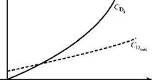
Wing DragFigure 6.18. Drag polar for profile and induced drag.

Example 6.3 Given: Consider a wing with a rectangular planform. The wing is untwisted and of constant section, with a lift-curve slope correction factor of t = 0.05. The wing span is 16 ft. and the chord is 2 ft. The measured profile-drag coefficient of the wing section is 0.005, the angle of zero lift of the section is -1.3°, and the section lift-curve slope is assumed to be 2n/radian.

The wing is to be tested in a wind tunnel at a geometric angle of attack of 7° at a test-section dynamic pressure of 1.5 psia.

Required: Find

(a) lift-curve slope of the wing, per degree

(b) lift coefficient of the wing

(c) lift force on the wing during test (lbs)

(d) drag coefficient of the wing

(e) approximate magnitude of the downwash

Approach: Use the various equations in this chapter, as appropriate.

Solution: Either the value of m must be converted to “per degree” at the end or m0 must be used as “per degree” at the outset. The latter choice is not as convenient but is used here to emphasize a point. Thus, m0 = 2n/radian = (2n)/ (180/n) = 0.1096/degree. As a further preliminary, AR = b2/S = b2/(b)(c) = b/c for a rectangular wing; hence, AR = 16/2 = 8 for this wing.

(a) Using Eq. 6.45:

Подпись: 0.087 / degree.______ mo________________ 0.1096_____

. m0(180 / n)(1 + t) _ 1 + (0.1096)(57.3)(1.05)

+ nAR + n(8)

(b) CL = m(a – aL0) = (0.087)[7 – (-1.3)] = 0.72.

(c) L = CL q„ S = (0.72)(1.5)(144)[(16)(2)] = 4,978 lbf.

(d) CDt = CDvisc + CL2/enAR = 0.005 +(0.72)2/(0.95)(8)n = 0.0267.

(e) The downwash may be estimated by using Eq. 6.43, valid for elliptical loading. Substituting w/V„ = tan(1.3°) = 1.3° _ 0.0227 radian, so that the downwash is 2.3 percent of the freestream velocity.

Appraisal: (a) Notice that with the choice of m0 in units of “per degree,” the numerator of Eq. 6.45 is expressed in “per degree,” which makes the answer for m as “per degree.” The ratio in the denominator of Eq. 6.45 must be dimension­less, so the value of m0 /radian must be used in the denominator.

(b) The magnitude of CL is reasonable and it is positive.

(c) Dynamic pressure must be converted to lbf/ft2.

(d) This is a typical value for using only drag.

(e) The downwash and the spanwise-flow components associated with the trailing vortex sheet are comparable in magnitude. Thus, assuming the flow over the wing to be locally two-dimensional is a good assumption.

Figure 6.19 is a comparison of experimental data and prediction using lifting-line theory. The theory was validated by many experiments and gives satisfactory results if the wing AR is not too small and the wing sweep is not excessive. When properly

Figure 6.19. Comparison of lifting-line theory with experimental results (see Anderson, 1984).
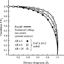
Wing Dragapplied, lifting-line theory provides a fast and accurate method for obtaining the continuous spanwise distribution of several quantities, such as lift and induced angle of attack.

Finally, we note that moments about finite wings and the location of the wing aerodynamic center and center of pressure can be calculated as weighted averages of the wing-section properties. These topics are not discussed here.

Remarks on Lift and Drag of a Finite Wing from Lifting-Line Theory

It is now useful to summarize and focus on important features of the lifting-line theory.

1. Lift-Curve Slope

Recall from Eq. 5.74 that the two-dimensional lift coefficient is given by:

C, = m0(« -«L0) = m0aa,

where aa is the absolute angle of attack. Because the angle of zero lift of the section is a function of the airfoil shape and, hence, is independent of a, the two­dimensional lift-curve slope is given by:

dC,

——l = m0 per radian (two-dimensional) (6.50)

da 0

Recall that m0 = 2n from thin airfoil theory.

Подпись: CL = C, = m0[(a - aL0)“ ai] = m0 Remarks on Lift and Drag of a Finite Wing from Lifting-Line Theory Подпись: (6.51)

Recalling Eqs. 6.42, 6.45, and 6.46, which are valid for an untwisted finite wing of constant section with an elliptical-lift distribution and constant a;, we write:

Solving:

Подпись: nARC = m0aa 1 + – ^

Remarks on Lift and Drag of a Finite Wing from Lifting-Line Theory Подпись: (three-dimensional, elliptical loading). (6.52)

Again, the zero-lift angle is independent of the geometric angle of attack so that:

This is the lift-curve slope for a finite wing. Using the thin-airfoil theory result for m0,

dCT 2n

—L = m =——— .

da і + 2 ‘ (6.53)

+ ~AR

Подпись: or Подпись: C da Remarks on Lift and Drag of a Finite Wing from Lifting-Line Theory Remarks on Lift and Drag of a Finite Wing from Lifting-Line Theory

These results, which specify the lift-curve slope for a finite wing with elliptical loading, may be modified to describe a wing with arbitrary spanwise loading by inserting a correction factor, t. Thus,

The correction factor, t, depends on the values of the An’s in the Fourier series and has a typical value of 0.05 < t < 0.20.

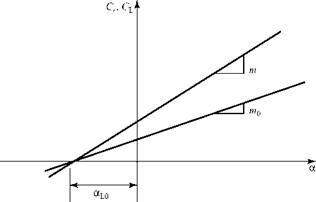
The lift-curve slopes for a two-dimensional airfoil and a three-dimensional untwisted wing of constant section with elliptical loading and the same airfoil section are compared in Fig. 6.17. Notice that the finite-wing effect is to reduce the lift-curve slope of the wing compared to that for the airfoil sections that comprise the wing.

Подпись: Figure 6.17. Comparison of lift-curve slopes.
Remarks on Lift and Drag of a Finite Wing from Lifting-Line Theory

When the airfoil lift coefficient is zero for a two-dimensional airfoil, Eq. 5.74, then a = aL0. For an untwisted wing of constant section with elliptical loading, Eq. 6.51 states that when CL = 0, then a = aL0 because a = 0. Because the airfoil and the wing in Fig. 6.17 have the same section, the intercept at Cl = CL = 0 is the same for both curves.

Wing Geometry Required for Elliptical Loading, Lifting-Line Theory

Подпись: 1 Wing Geometry Required for Elliptical Loading, Lifting-Line Theory

It is shown in the previous section that elliptical-spanwise loading corresponds to minimum induced drag. There are three ways to design a wing to achieve elliptical – spanwise loading: (1) using a suitable wing planform, or (2) using wing twist, and it can be approximated (3) using a simple tapered planform.

where K = (T0/qsCt), which is a constant. Thus, the variation of the wing chord, c, with span, y, is given by:

Подпись: (6.48)K2 (b / 2)2

ro

f 1 }

f 2 CLVsS ^

f 4S Ї

f Cl ^

4S

qC

1 q~C1J

1 nb J

tp Vsnb J

v CL J

pVjnh

which is the equation for an ellipse. The constant K is independent of lift because from Eq. 6.39:

K=

Eq. 6.48 states that if a wing is untwisted and of constant section with constant lift-curve slope, then an elliptical-lift distribution is generated if the wing has an elliptical planform. Furthermore, the elliptical-lift distribution occurs at any value of wing-lift coefficient. Thus, elliptical-lift distribution can be achieved in practice but at the cost of complexity of manufacture.

2. Twist

Assume (for simplicity) only that m0 = constant for any wing section. A geo­metric twist (varies with span) or an aerodynamic twist (aLo varies with span) or both are permitted. The induced angle of attack, a;, is a constant because of the elliptical-loading requirement. Then, from Eq. 6.45:

CL= mo(« -«i -“L0 ),

Wing Geometry Required for Elliptical Loading, Lifting-Line Theory Подпись: (6.49)

and using Eqs. 6.36 and 6.42:

The local variation of wing chord as expressed by c(y) and wing twist as expressed by the absolute angle of attack aa(y) = [a(y) – aLo(y)] must be such as to satisfy Eq. 6.49 for all values of y. In particular, for a rectangular wing of constant sec­tion, Eq. 6.49 shows that an elliptical spanwise loading can be achieved provided that the geometric twist of the wing also varies elliptically with span. However, because CL does not cancel out in Eq. 6.49, this twist provides elliptical spanwise loading at only one (design) value of wing-lift coefficient. Again, as in the case of an elliptical planform, spanwise elliptical loading can be achieved at the cost of fabrication complexity.

3. Tapered Wing

Recall from Eqs. 6.31 and 6.44 that a wing of arbitrary planform with arbitrary spanwise loading has an induced drag that is a factor (1 + 5) larger than that for elliptical loading. A straight-tapered wing with a taper ratio of about 0.4 has a value of 5 or about 0.01. Thus, this wing—which is relatively straightforward to manufacture—has an induced-drag coefficient that is only about 1 percent above the minimum. We verify this conclusion by running Program PRANDTL for various taper ratios and examining the values of induced drag in the neigh­borhood of a taper ratio of 0.4.

Forces on an Arbitrary Finite Wing from Lifting-Line Theory

We now apply the lifting-line theory to estimate important aerodynamic properties of a finite wing of arbitrary shape and airfoil.

1. Lift Force

From the Kutta-Joukouski Theorem, the lift per unit span is related to the circu­lation by L’= рУгоГ. Thus, the total lift on the wing is obtained by integrating the lift per unit span across the span; namely:

b/2 b/2

L= J L’dy ^ L’ = Г(y)dy. (6.28)

-b/2 – b/2

Подпись: C Подпись: L 1/2рVfS Подпись: 2 b/2 FS J Г(y)dy. “ -b/2 Подпись: (6.29)

The wing-lift coefficient is given by:

Standard notation is that the forces on a three-dimensional wing are unprimed, and the wing-force coefficients are written with an upper-case subscript. The nondimensionalization is with the wings planform area, S.

Forces on an Arbitrary Finite Wing from Lifting-Line Theory Forces on an Arbitrary Finite Wing from Lifting-Line Theory Подпись: (- sin 0d0

Transforming to the angular-measure variable, 0, and integrating:

The product [(sin(n0))(sin)], when integrated between the limits n and 0, is zero for n Ф 1. Thus, only the Ai term remains and:

CL = nAiAR. (6.30)

Recall that the aspect ratio, AR, is a wing-planform property and AR = b2/S.

Eq. 6.30 shows that the wing-lift coefficient depends on only one Fourier – series coefficient. This does not mean that the fundamental monoplane equation must be applied at only one spanwise station. The more simultaneous equations that are generated for the An’s, the more accurate is the value for Ai.

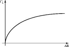
The variation of wing-lift coefficient with AR for a tapered wing is shown in Fig. 6.15. This is not simply a linear plot, as Eq. 6.30 might suggest, because the value of Ai changes with AR. Wing lift and the wing lift-curve slope are discussed later.

Figure 6.15. Variation of the wing-lift coefficient with the AR for a tapered wing.

Forces on an Arbitrary Finite Wing from Lifting-Line Theory2. Induced Drag Force

From Eq. (6.18), the induced drag is given by D = L’a;. Then, L’ may be written as a Fourier-series expression by using Eqs. 6.17 and 6.23. The expression for a; is given by Eq. 6.15 and the integral in Eq. 6.15 already was evaluated as Eq. 6.26. Dropping the subscripts in Eq. 6.26:

Подпись: b/2

A= J [L’][ai](dy):

Подпись: = J Forces on an Arbitrary Finite Wing from Lifting-Line Theory Подпись: . sinn0 Подпись: - b sin 0d0 2

-b/2

Подпись:Подпись: d0.

Forces on an Arbitrary Finite Wing from Lifting-Line Theory

and

We note that the integrand is the product of two summations. The running sub­script in the second summation is changed to m to emphasize this point. Now:

n j 0 n * m

J sin и0sin m0d0 = – j n

0 (2 n=m.

Expanding the two Fourier-series, multiplying term, by term, and then integrating yields:

CD =2AR

‘n’

о

A2 + Z nAn2

= nAR( A-j2)

1+Zn

( л2 ‘ A2

V 2 J

_ n=2 _

n=2

V A12 JJ

Notice that the summation is always a positive quantity, because all of the An’s appear as the square. This summation has a value that depends on the values of the Fourier-series coefficients and, hence, on the wing planform. We give this summation the symbol 5 , which is known for a specified wing planform. Finally, we use Eq. 6.30 to substitute for Ab The result is:

This is an important result. It states that the induced-drag coefficient depends on the lift coefficient squared, so that a portion of the drag of an airplane is the result of the production of lift. Notice the importance of the AR. Recall the dis­cussion in Chapter 1 about the Voyager airplane used for the first nonstop flight around the earth and the illustrations showing high-performance sailplanes. ARs that sometimes exceed 50 are used as one of several drag-reducing design features for such specialized aircraft, which require the lowest possible drag in the lower speed range. (Boermans, 2006 and Dillinger and Boermans, 2006).

Because § > 0, then for a given AR, the induced drag is a minimum when § = 0. The conditions necessary for this to be so are studied shortly. The quantity (1 + §) often is written as 1/e, where e is called the span efficiency factor. This parameter is used frequently in the aeronautical industry as a measure of the efficiency of the wing design in reducing induced drag. For minimum induced drag, e = 1.0. As induced drag increases, the value of e decreases. Then, Eq. 6.31 may be written alternately as:

For a typical wing, § is a small quantity on the order of 0.05 (corresponding to e = 0.952). Thus, the AR has a much larger role in setting the magnitude of the induced drag than the span-efficiency factor. Induced drag is discussed further in a subsequent section.

Подпись: Program PRANDTL. This program solves the monoplane-wing equation for straight tapered-wings. The user selects the number of Fourier-series coefficients to be used in the solution as well as the wing AR, taper ratio, twist, and angle of attack. The program calculates the values of the Fourier-series coefficients, the wing lift and induced drag, and the span-efficiency factor. Examine the effects of these parameters by running several cases of your choice, compare the results, and note the trends.

Now, we run Program PRANDTL to explore the dependence of lift and induced drag on all of the parameters that describe a tapered wing.

Elliptic-Lift Distribution

The results for the calculation of the induced drag of an arbitrary finite wing, Eq. 6.32, indicated that the drag was least when all of the An’s in the Fourier series were zero for n >1. This section examines the performance of a wing when the
induced drag is minimum and then investigates the wing geometry that is necessary to achieve this minimum induced-drag condition.

1. Elliptic Loading

The general Fourier-series expression for Г(0), the spanwise circulation distri­bution, is given by Eq. (6.23). With all of the An’s set equal to zero except Ab this equation reduces to:

Г = 2bV^A1sin 0 (6.33)

At the root section y = 0 (0 = n/2), let Г = Г0, where:

Подпись: (6.34)Подпись: (6.35)Г0 = 2bV^Ai.

Then, Eq. 6.34 may be written as:

Г = Г0 sin 0.

Подпись: sin2 0 + Подпись: b/2 Forces on an Arbitrary Finite Wing from Lifting-Line Theory

Now, we recall from a trigonometric identity that sin2 + cos2 = 1. We also recall from the spanwise location transformation, Eq. 6.22, that y = (b/2) cos 0. It follows that:

Forces on an Arbitrary Finite Wing from Lifting-Line Theory Подпись: (6.36)

Then, substituting this relationship into Eq. 6.35 and rearranging:

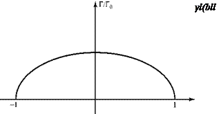
which is the equation for an ellipse in y-Г coordinates, as illustrated in Fig. 6.16. This result states that if the bound vorticity, or circulation Г, and therefore the lift per unit span, L’, is distributed eliptically across the wing span (i. e., elliptical loading) then the induced drag is a minimum.

Forces on an Arbitrary Finite Wing from Lifting-Line Theory Подпись: Figure 6.16. Elliptical spanwise loading for minimum induced drag.

The elliptical-loading results that follow are useful because they represent a standard for comparison. They also are used as a basis to express results for arbi­trary spanwise loading by means of a correction factor (compare Eqs. 6.32 and 6.44).

In the remainder of this section, notice the repeated appearance of the ratio b2IS, which is the reason that the special name aspect ratio was given to this quantity. Also notice the primary role of the AR in both the elliptical-spanwise-loading results and those for arbitrary spanwise loading.

2. Wing Lift

Recall that L’ = рУ^Г and use the spanwise-location transformation, Eq. 6.22. Then, for elliptical loading, Eq. 6.35, the wing lift is given by:

Подпись: - b cos0d0 2b/2 0

L= J L’dy = Jpyjr„sin0]

Forces on an Arbitrary Finite Wing from Lifting-Line Theory Forces on an Arbitrary Finite Wing from Lifting-Line Theory

-b/2

3 Downwash

Forces on an Arbitrary Finite Wing from Lifting-Line Theory Forces on an Arbitrary Finite Wing from Lifting-Line Theory

The general expression for the downwash is given by Eq. 6.10, where dr/dy may be written as (dr/d0) (d0/dy). For elliptical loading, dr/d0 = r0cos 0 from Eq. 6.35. Thus, Eq. 6.10 becomes:

Inverting the limits and placing a minus sign in front of the integral to compen­sate, the integral has a principle value of n, given by Eq. 6.25 with n = 1. The downwash at any point along the span then is given by:

Г

w = –°. (6.40)

Forces on an Arbitrary Finite Wing from Lifting-Line Theory Подпись: СУ nAR Подпись: (6.41)

This equation indicates that in the special case of elliptical loading, the down – wash is a constant all along the span. Thus, for a wing with elliptic loading, stall occurs all along the span at the same time. Now, using Eq. 6.39:

The magnitude of the downwash thus depends on the magnitude of the wing-lift coefficient and varies inversely as the wing AR.

4. Induced Angle of Attack

The expression for the induced angle of attack follows from Eq. 6.43 and the definition of a;, Eq. 6.14. Thus,

Подпись: ro = 2ЬУж nAR
Подпись: —w a- = — 1 Uc~
Подпись: (6.42)

and the Induced angle of attack also 1s constant across the span.

5. Induced Drag

Forces on an Arbitrary Finite Wing from Lifting-Line Theory Подпись: (6.43)

From Eq. 6.18, D = L’a so that:

and us1ng Eq. (6.42):

Подпись: (6.44)C

CD= CD =

1 Dimin nAR

The Induced drag Increases as the lift coefficient 1s squared.

6. Relations ships Between Section and Wing Coefficients

From Eqs. 6.12 and 6.13, the section-lift coefficient for a finite wing may be written as:

Ct = mo(a — a i — «L0). (6.45)

Now, we assume an untwisted wing of constant section with elliptical loading. Under this condition: a = constant across the span, untwisted (no geometric twist) wing aL0 = constant across the span, wing of constant section a; = constant across the span, elliptical loading

The two-dimensional lift-curve slope, m0, has the theoretical value 2n, and experi­mental values are not greatly different from that value. Then, if m0 is assumed constant, for an untwisted wing of constant section with elliptical spanwise-lift distribution, Eq. 6.45 states that the section-lift coefficient, Cl, must be constant across the span and further more that:

– ь/2 – ь/2 c ь/2

CL =J L’dy = 1 [<7Cic]dy = ~^ J cdy = C – (6.46)

q°°S —Ь/2 q°°S —Ь/2 S —Ь/2

Forces on an Arbitrary Finite Wing from Lifting-Line Theory Подпись: Ь/2 — J ai = ^ q-S —Ь/2 Подпись: (6.47)

because the integral of the chord over the span is simply the planform area. Thus, under these assumptions, the numerical value of the section and wing-lift coefficients is the same. Similarly,

so that under these same assumptions, the numerical value of the section and wing induced-drag coefficients are the same.

Spanwise-Lift Distribution on an Arbitrary Wing by Lifting-Line Theory

When faced with solving an integro-differential equation to find the chordwise- vorticity distribution in two-dimensional airfoil theory (see Chapter 5), a Fourier – series representation for the chordwise vortex-strength distribution, y(x), is used. Here, a Fourier series is used to represent the unknown bound-vortex-strength dis­tribution, Г(у), in Eq. 6.21. As in Chapter 5, a transformation is made to relate a span – wise linear location to a location described by angular measure. For example, a circle of radius b/2 with the center at mid-span and measuring the angle 0 from the positive у axis (Fig. 6.14). The required transformation is:

b

b/2 7

Now, we assume a Fourier-series representation of the bound-vortex-strength distri­bution as given by:

Г(0) = {WVJ^An sinnG, (6.23)

n=1

where An are unknown constants. Because L’ (hence, Г) must be zero at the wing tips by physical argument, there is no lead constant term in the series. For symmetrical spanwise loading, all of the cosine terms vanish because they never make a sym­metrical contribution about the wing plane of symmetry, y = 0 or 0 = n/2 and because the cosine is positive for 0 < 0 < n/2 and negative for n/2 < 0 < n. The coefficient (2b VJ is introduced for convenience from hindsight. Equation 6.23 is a solution only if a method for finding the An’s can be established.

We examine the integral term in the defining equation, Eq. 6.21 and call it I. Writing:

dr = dr d0

dy d0 dy ’

1 bb2 (dr/dy)

4nV~-b/2 (Ус"У)

Подпись: I = Spanwise-Lift Distribution on an Arbitrary Wing by Lifting-Line Theory

the integral term becomes, with the aid of Eq. 6.22:

Using Eq. 6.23 to find dr/d0 in the integrand and inverting the limits of integration, this expression for I may be written as:

1 ~ П cos n0

– n=1 (cos 0- s 0)d0. (6.24)

Spanwise-Lift Distribution on an Arbitrary Wing by Lifting-Line Theory Подпись: n sin n0O sin 0O

As in two-dimensional thin-airfoil theory, this integrand has a singularity when the running variable of integration, 0, is equal to the fixed angle 0O, which denotes the spanwise station of interest. The “principle value” of this integral is used here as in Section 5.14, Eq. 5.57; namely:

Подпись: 1 = -£ M, n=1 Подпись: sin n 0Q sin 0O Подпись: (6.26)

Then, the integral in Eq. 6.24 becomes

Finally, we substitute this expression for the integral in the defining equation, Eq. 6.21, and drop the subscript “0” because the equation must hold at any general spanwise station:

4b ^ – sin n0

a(0)=0. (6.27)

0 n=1 n=1

This is the equation for determining the Fourier-series coefficients, An. The coefficients are found by applying Eq. 6.29 at several spanwise stations specified by different values of 0 (see Example 6.2). At each station, c, a, and aL0 are known. Thus, a set of simultaneous equations is generated, which can be solved for the unknown An’s. The more terms that are taken in the series (i. e., the more spanwise stations at which Eq. 6.27 is applied), the more accurate are the coefficients and the theoretical results. With the An’s known, the spanwise loading follows from Eq. 6.23.

If the spanwise loading is symmetrical, then Г(0) = Г(-0). That is, symmetry demands that:

^ Ansm n0 Ansm n(n-0).

n=1 n=1

Expanding the right side of this equality:

N N

^ An sm n0 = ^ An [sin nn cos n0 – cos nn sin n0).

n=1 n=1

Now, sin nn is zero for all integers n, but cos nn = -1 only for n odd. So, if the identity is to be satisfied, there can be no terms appearing with n even. This means that for symmetrical loading the An’s must be zero for all even values ofn. Likewise, for sym­metrical loading, we need only calculate the spanwise loading for one semi-span. The loading on the other semi-span is simply a mirror image in the plane of symmetry.

Example 6.2 Given: A wing planform is shown here. This wing has a constant sec­tion with a section lift-curve slope of m0 = 6.7 per radian and an angle of zero lift of -1.5°. The wing is symmetrical about y = 0. The wing has geometric twist, with a geometric angle of attack of 4° at the wing root, decreasing linearly with semi-span to 2° at the tips.

Required: Calculate the spanwise loading on this wing. For convenience, cal­culate only two terms in the Fourier-series expression for r(y). Evaluate the coefficients of these terms at mid-span and at half-semi-span.

Approach: Write two simultaneous equations for the two unknown Fourier-series coefficients. Because the wing is symmetrical, all of the even An’s are zero. The two simultaneous equations for A1 and A3 are obtained by writing Eq. 6.23 twice, once at the spanwise location at y = b/4 (0 = п/3) and once at mid-span (0 = п/2).

Подпись: a = 4o -2° Spanwise-Lift Distribution on an Arbitrary Wing by Lifting-Line Theory Подпись: •y = 0 a = 4o; y = 2,a = 2o

Solution: Here, the angle of zero lift is a constant across the span. Because the geometric angle of attack varies linearly, we write the following from the given:

Regarding the chord, from the given geometry of the planform, it is 10 ft. at the root and 7.5 ft. at mid-semi-span. Then, writing Eq. 6.23 at mid-span,

Spanwise-Lift Distribution on an Arbitrary Wing by Lifting-Line Theory Spanwise-Lift Distribution on an Arbitrary Wing by Lifting-Line Theory

y = 0, 0 = п/2, c = 10:

Spanwise-Lift Distribution on an Arbitrary Wing by Lifting-Line Theory Spanwise-Lift Distribution on an Arbitrary Wing by Lifting-Line Theory

Again, at mid-semi-span, y = b/4, 0 = п/3, c = 7.5:

solving for the two unknowns, A1 = 0.018 and A3 = -0.0047.

Thus, to two terms:

Г = 2(40)R4(0.018)sin 0 – (0.0047) sin 30]

from Eq. (6.25).

Appraisal: The angles that appear in the defining equation must be expressed in radians. The resulting expression for Г(0) can be expressed as r(y) through the transformation, Eq. 6.24, and evaluated at several values of y, giving the spanwise loading L’ across the span using Eq. 6.18. The loading is symmetrical about y = 0. The number of stations at which the loading is evaluated is indepen­dent of the number of stations used to calculate the An’s. However, the more spanwise stations at which the fundamental equation is applied, the more simul­taneous equations are generated, and the more accurate is the Fourier series representation for r(y). In the previous example, if a third station was used to generate a third simultaneous equation, the coefficient A5 would be introduced and the values of A1 and A3 would change. The sensitivity of the values of An to the number of simultaneous equations used may be studied by running Program PRANDTL, which is introduced shortly. In this program, the user selects the number of Fourier-series coefficients desired and the computer program solves the simultaneous equation set.

A method for determining the spanwise-lift distribution on a wing of arbitrary planform is now established. Fig. 6.13 shows a calculated spanwise loading, Г(у), for an untwisted tapered wing of constant section at a fixed geometric angle of attack. The loading is nondimensionalized by the value of the circulation at mid-span (У = 0), Г= Го.

Recalling the results in two-dimensional airfoil theory, we might suspect that an integration to find the total forces on the wing would result in a dependence on only a few of the Fourier-series coefficients. This is investigated next.

Wing Twist

Until now, the wing planform is assumed to be rectangular and aL0 is considered constant across the span. These restrictions are dropped before the fundamental wing equation is written.

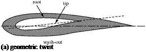
If a wing planform is tapered, for example, then the wing chord is different at each spanwise location, y0, of interest. This chord is denoted by c(y0). As noted previously, the induced angle of attack is generally different at each spanwise station of interest; hence, the notation, aj(y0) is used. If the wing has twist, then the geo­metric angle of attack, a, and the angle of zero lift, aL0 may be different at different spanwise stations, y0. There are two types of wing twist as follows: 1 [24]

Figure 6.12. Geometric and aerodynamic wing twist.

Подпись:Wing Twisttransition from one section to the next would be smooth. Aerodynamic twist has the effect of making aL0 take on a different value at a different spanwise station of interest; that is, aL0 = aL0 (y0).

A wing may have geometric or aerodynamic twist or both, in which case the effects are added. The amount and type of twist are specified for a given wing. Wing twist is used to modify the spanwise-loading distribution over a wing planform. For example, Fig. 6.13 shows the distribution of bound-vortex strength or, by definition, Cl (see Eq. 6.19) along an untwisted wing of constant section with moderate taper. We notice in this figure that there are larger values of Г at some spanwise stations than at others. Thus, at about 60 percent semi-span, the local airfoil section is oper­ating at a comparatively large value of aeff (see Eq. 6.14). The section at 2y/b = 0.60 is “working harder” than, say, the section at mid-span. Thus, as the geometric angle of attack of the wing is increased, the wing stalls first at about 60 percent semi-span. This may render ineffective a portion of a control surface or flap located near that spanwise station because it would be immersed partially in a “dead air” separated flow. Incorporating wing twist into the wing design could modify the spanwise dis­tribution of aeff such that the wing would first stall farther inboard. An alternative method for tailoring the spanwise stall characteristics of a wing by modifying (i. e., “drooping”) the shape of the wing leading edge is in Abbott and Van Doenhoff (1959).

Подпись: 0Г/Г

Подпись: Figure 6.13. Spanwise loading on a tapered wing.Wing Twisty/(b/2)

Fundamental Monoplane Wing Equation

Подпись: CL (У0)
Подпись: L( y0) = 2Г( y0) 1 PVlc( У0) V c( У0) Подпись: (6.19)

This equation is written for a twisted wing of nonrectangular planform. It may be simplified as appropriate. First, by definition:

Next, substituting Eq. 6.13 into the expression for Cl in Eq. 6.12 and introducing the new notation:

Ci (Уо) = m H Уо b «i( УоЬ aL0 (%)]. (6.20)

Finally, we solve for a (for convenience):

a( Уо) = + a lo (Jo) + ai(Уо)

m0

Wing Twist Wing Twist
Подпись: dy Подпись: (6.21)

and substitute for CL(y0) from Eq. 6.19 and for ai(y0) from Eq. 6.15. The result is:

where the speed and chord distribution, то and aLo, are known for a given wing.

Eq. 6.21 is called the fundamental wing equation for a monoplane (i. e., for a single wing). This equation can be used to solve for Г(уо)—that is, for the distribution of bound vorticity—across the span. The solution process is not straightforward because Eq. 6.21 is an integro-differential equation for the unknown circulation strength.

The central problem of lifting-line theory is to determine the spanwise distri­bution of circulation—that is to find Г(уо) = Г(у)*—as a function of wing-shape parameters. If Г(у) can be found, L'(y) follows directly. Then, the wing total lift is given by the integration of L’ over the span, and the induced drag may be calculated from Eq. 6.18. Although circulation is not a physical variable, it is simplest to work with Г(у) as the unknown. Once Г(у) is found, the finite-wing problem is solved. A Fourier-series solution is discussed in the next section.

Lift and Induced Drag

Подпись: L' = F 'cos aj = p Vr cos aj = p Vr Подпись: V V Подпись: (6.16)

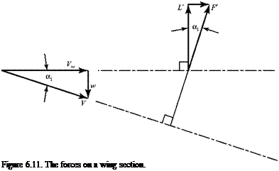
The effect of the presence of downwash also must be examined from the viewpoint of the forces on a wing section. Consider Fig. 6.11. The Kutta-Joukouski Theorem states that the force generated by flow over a bound vortex per unit span is given by F’= pFT and is normal to V—that is, normal to the relative wind. (In two dimensions, the relative wind is the freestream and the force perpendicular to this wind is then the lift force.) It follows from Fig. 6.11 that:

or, finally

Подпись: (6.17)L = pV^T.

Подпись: Figure 6.11. The forces on a wing section.

This is identical to the two-dimensional result.

Notice, now, in Fig. 6.11 that the effect of the downwash is to tilt back the force vector, F ‘, at the lifting line; it is no longer perpendicular to the freestream direc­tion as it was in the two-dimensional case. There is now a component of F’ in the freestream direction that, by definition, is a drag force. This drag force is called the induced drag because it arises due to the presence of the downwash, which is caused by the velocity induced by the trailing-vortex sheet. The induced drag per unit span is given the symbol D. Then, because a is small (see Example 6.3):

Dj = L’ tan aj = L’Oj. (6.18)

The induced drag is an important new concept. It was not present in two-dimen­sional airfoil theory because there was no trailing-vortex sheet present in that theory. Induced drag arises in inviscid finite-wing theory. It is the price for gener­ating lift with a three-dimensional wing. Induced drag may be thought of physically as representing energy left behind an advancing wing. This energy is in the form of translational and rotational kinetic energy present in the trailing vortices. These vortices are deposited in the atmosphere and, ultimately, are dissipated by viscosity.

Induced drag is a significant drag contribution. Although aj is small, in Eq. 6.18, it multiplies the lift per unit span, which is a large number proportional to the weight of the flight vehicle. Thus, induced drag must be studied and methods sought to mini­mize the magnitude of this drag. Recall from Chapter 1 that flight-vehicle perfor­mance and efficiency are directly dependent on making the drag from all sources as small as possible.

Induced Angle of Attack

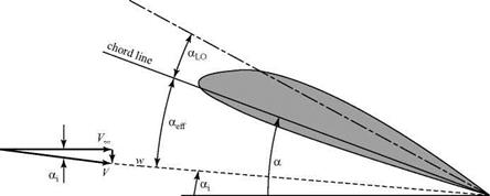
Notice in Fig. 6.10 that the lifting line is now exposed to a relative wind, V, which is the vector sum of VM and the downwash, w. Thus, the local airfoil section behaves as if the geometric angle of attack, a, has changed by an amount a;, the induced angle of attack. This is the viewpoint that is carried forward—namely, that the angle of attack of the wing section was modified due to the presence of the vortex sheet.

Referring to Fig. 6.10, the concept of relative wind at the lifting line in Fig. 6.9 may be generalized to include the wing-section angle of attack and camber.

The angle of attack to which the wing section responds is no longer the geo­metric angle of attack, a, but rather the (smaller) effective angle of attack, aeff. Camber may be included in the section shape by introducing the zero-lift angle, aL0. Two-dimensional airfoil results may be used to specify aL0 for a particular wing section. When the line ZLL (see Fig. 6.10) is aligned with VM the lift of the airfoil section (behaving two-dimensionally) is zero. If a finite wing is set to a zero-lift condition, then a wing zero lift line (ZLLW) may be specified that is identical all across the span. A wing angle of attack, aaw, then can be defined as the angle between the freestream and the ZLLW.

Now, we recall from two-dimensional thin-airfoil theory Eq. 5.74 that the lift coefficient of a thin airfoil is given by:

Cl = mo(a — aLo), (6.11)

where the two-dimensional lift-curve slope, m0 per radian, may be assigned the theoretical value of 2n or a value from experiment. Equation 6.11 also may be written with the lift-curve slope as a0, where m0 is per radian and a0 is per degree.

Because a section of a three-dimensional wing is assumed to behave locally as a two-dimensional airfoil, it follows that for a finite-wing section:*

Cl = mo(aeff – aLo). (6.12)

ZLL

Induced Angle of Attack

Figure 6.10. General wing section at the angle of attack.

In some texts, the quantity (aeff — aLo) is written as Oq.

Finally, from the geometry shown in Fig. 6.12, at every spanwise station:

aeff = a – Oj, (6.13)

where aj is a positive angle. From Fig. 6.11:

w

tan aj = – —= a-. (6.14)

V ж [23]

Recall that the downwash, w, is a downward-directed velocity component in Car­tesian coordinates and is negative. Hence, a minus sign must be introduced in Eq. 6.14 so that the induced angle of attack, aj, is a positive angle. In general, the induced angle of attack varies across the span.

Подпись: a = Подпись: 1 bf d / dy) 4VJ/2 (У - У0) У Подпись: (6.15)

The mathematical expression for the induced angle of attack follows from Eq. 6.14 and the equation for downwash, Eq. 6.10:

Downwash

The induced velocity at the lifting line is given a special name: the downwash. It is assigned the velocity component symbol w and enters with a negative sign because the induced velocity is in the negative z-coordinate direction.

Подпись: V = — p 4nh Downwash Подпись: (6.8)

Recall that the Biot-Savart Law states that for a semi-infinite vortex filament extending from Point Q to infinity, as shown in Fig. 6.4 and Eq. 6.4, the induced velocity is given by VP = Г /4nh. This velocity is normal to the plane containing the filament and Point P. We apply this result to an arbitrary single filament in Fig. 6.8 and assume that the filament trails in the direction of VTC. The induced velocity (i. e., downwash) at a fixed but arbitrary Point y0 on the lifting line, due to a semi­infinite vortex filament of strength dr that originates at the lifting line at a spanwise location y and trails downstream, is given by:

Points Q and 2 (at downstream infinity) in Fig. 6.8 aid in orientation with Fig. 6.4. This induced velocity is in the z direction. We note that because Eq. 6.8 is simply a repeat of Eq. 6.4, an integration over the streamwise length of the trailing – vortex filament already occurred. Eq. 6.8 is written as dw to emphasize the fact that this is the induced velocity due to only one trailing filament of infinitesimal strength.

Substituting the expression for dr from Eq. 6.7,

Подпись:

Подпись: dwy0 Downwash Подпись: (6.9)

( dr

Finally, we check the sign. Referring to Fig. 6.8, for the spanwise locations chosen, y > y0 and the sense of the trailing-vortex filament is counterclockwise looking upstream. The velocity induced at y0 then should be downward, or dw should be negative. Now, from Fig. 6.8, the distribution over the right half-wing is such that the rate of change with y is negative. Thus, Eq. 6.9 is physically correct as written.

Downwash Downwash Подпись: (6.10)

Because Eq. 6.9 represents the downwash contribution at y0 due to one semi­infinite filament, it remains to calculate the total downwash at y0 due to all of the trailing-vortex filaments from the wing that comprise the vortex sheet. This amounts to a summing, or integration, over y; namely:

Notice that as we sum across the span, some filaments induce an upward component and others a downward component at Station y0, depending on the relative magni­tudes of y and y0 and also on which half-wing is considered. Equation 6.10 is the sum total of all of these contributions and is directed downward for positive lift on the wing. The singular behavior of the integrand when the integration variable, y, has the specific value y = y0 is addressed in due course.

Figure 6.9 shows a cross section of a wing according to the lifting-line model. The wing is in an oncoming freestream VTC. Because a vortex filament does not induce any velocity (think of the vortex as exhibiting viscous-dominated, solid-body rotation at the center), the only other velocity component at the wing quarter-chord (i. e., at the lifting line) is the downwash due to the trailing-vortex wake, shown in Fig. 6.9. Because the vortex sheet is aligned with VTC, the downwash component w = Vs is perpendicular to VTC. For positive lift, the downwash at the lifting line always is directed downward.

Подпись: Г w Figure 6.9. Velocity components at the lifting line.

Assumptions of the Lifting-Line Theory

In classic lifting-line theory, the wing is represented by a single finite-strength vortex or lifting line and the trailing-vortex sheet is assumed to be planar and parallel to the oncoming flow. Normally, the vortex sheet is assumed to be in the plane z = 0. Thus, the wake can induce velocity components in the x-y plane only in the z direction—that is, in a direction perpendicular to the lifting line. In particular, the wake cannot induce any velocity components in the spanwise (y) direction in the plane z = 0 containing the lifting line. Of course, the wake also can induce velocity components above, below, and beyond the span of the lifting line, but none of these are of interest in our flow model.

The basic lifting-line theory, then, neglects the spanwise velocity components induced at the lifting line by the trailing-vortex sheet. Thus, each airfoil section behaves as if the flow were locally two-dimensional. This assumption is at odds with the physical argument used previously that the spanwise velocity mismatch at the wing trailing edge gives rise to the trailing-vortex filaments. However, neglecting the spanwise-velocity components gives satisfactory results because they are small, typically a few percentage points of VTC. The assumption of local two-dimensionality is worst at the wing tips, where the spanwise flow is large, but this area represents only a small fraction of the entire wing. One advantage of this assumption is that it allows a two-dimensional treatment of the downwash at the lifting line. Also, if each airfoil section behaves as if it were in a locally two-dimensional flow, then the chordwise pressure-distribution detail on the wing—which is lost in the lifting-line model—is available from two-dimensional airfoil theory or experimental data as in Chapter 5. The fact that the two-dimensional airfoil section is part of a finite wing is manifested by a modification in the angle of attack at which the section is operating. Finally, experimental data for two-dimensional airfoils may be used to predict the viscous drag of the wing. Thus, the advantages of using this assumption of negli­gible spanwise flow are many and the theory still exhibits satisfactory accuracy. If the wing is highly swept or of very low AR, then the spanwise-flow component is large, the assumption is invalid, and the simple lifting-line theory breaks down. The simple theory has been extended to treat swept wings, but this is not discussed here. The method becomes complicated and the problem is solved more easily numerically.

Because the lifting line represents the wing, it is positioned at the wing quarter- chord. This is because (1) each airfoil section comprising the wing acts as if the flow were two-dimensional (i. e., the trailing vortices present in the model induce no span – wise-velocity components); and (2) the lift force on an arbitrary two-dimensional airfoil in incompressible flow (see Chapter 5) acts at the aerodynamic center (i. e., at c/4), according to thin-airfoil theory. Recall that the assumed chordwise-vorticity distribution that led to this result (see Fig. 5.17) was chosen so as to satisfy the Kutta condition. Thus, placing the lifting line at the wing quarter-chord results in the Kutta condition being approximately satisfied all along the wing trailing edge.