Category Basics of Aero – thermodynamics

Wall Compatibility Conditions

In the continuum flow regime the no-slip condition at the surface of a body (tangential velocity components uw = ww = 0) is the cause for the devel­opment of the boundary layer. We assume for the following consideration preliminarily uw = ww = 0, and also that the normal velocity component at the body surface is zero: vw = 0, although vw/vref ^ O(1/Reref) would be permitted. We formulate

uy=o = 0, wy=o = 0, vy=o = 0. (7.47)

In addition, we can make statements about derivatives of u, w and v at the surface. The classical wall compatibility conditions for three-dimensional flow follow from eqs. (7.37) and (7.39). They connect the second derivatives of the tangential flow components u and w at the surface with the respective pressure gradients

Подпись:(7.48)

Подпись:d dw dp

^%)ly=° = d-Z-

Wall Compatibility Conditions Подпись: (7.50)

The first derivatives of u and w at the surface in attached viscous flow are by definition finite. In external streamline coordinates, Figs. 7.1 a) and 7.2, we obtain for the main-flow direction

and for the cross-flow direction

lv=o£0. (7.51)

The first derivative at the surface of the normal velocity component v in у-direction is found from the continuity equation, eq. (7.36)

‘Л

^lv=o = 0. (7.52)

Wall Compatibility Conditions Wall Compatibility Conditions Wall Compatibility Conditions

For hypersonic attached flow we generalize now the classical wall-compati­bility conditions by taking into account (also in external streamline coordi­nates) possible slip flow (uw k 0, ww ^ 0), suction or blowing (vw ^ 0), and temperature gradients in the gas at the wall (dT/dyw ^ 0), assuming that all obey the boundary-layer assumptions. We find, again from eqs. (7.37) and (7.39)

The functions of the tangential velocity components u(y) and w(y) and their derivatives at the outer edge of the boundary layer in first-order boundary-layer theory are found from the asymptotic condition that the
boundary-layer equations approach there the (two-dimensional) Euler equa­tions. From eqs. (7.37) and (7.39) we get
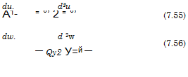
Подпись:Подпись: uПодпись: e:Подпись: wПодпись: euy=5

wy=S

Подпись: dfxv Подпись: dpu dpw dx ^ dz Подпись: y=S Подпись: dpeue dx Подпись: dpewe dz Подпись: (7.57)

The normal velocity component v(y) is not defined at the outer edge of the boundary layer, nor its second derivative. From eq. (7.36) we find only the compatibility condition

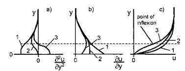
The compatibility conditions permit to make assertions about the shape of boundary-layer velocity profiles. We demonstrate this with the profile of the tangential velocity component of two-dimensional boundary layers, Fig. 7.1 a), which also holds for the main-flow profile of three-dimensional boundary layers, Fig. 7.1 b). The result is particularly important for stability consider­ations of the laminar boundary layer (point-of-inflection criterium). We will come back to it in Sub-Section 8.1.3.

We consider three possible values of d2u/dy2w: < 0 (case 1), = 0 (case 2), > 0 (case 3), Fig. 7.4. We see that the second derivative (curvature) is negative above the broken line for all profiles given in Fig. 7.4 a). Hence the second derivative will approach in any case d2u/dy2y=g = 0 with a negative value, Fig. 7.4 a). It can be shown by further differentiation of the x-momentum equation, eq. (7.37), that for incompressible no-slip flow also

d3u.

^зІ«=о = 0. (7-58)

With these elements the function d2u(y)/dy2 can be sketched qualita­tively, Fig. 7.4 a). Because we consider attached viscous flow, du/dyw > 0 holds in all three cases, Fig. 7.4 b). We obtain finally the result that boundary – layer flow in cases 1 and 2 has profiles u(y) without a point of inflection, and in case 3 has a profile u(y) with a point of inflection.

The interpretation of this result, Table 7.1, is found through a term by term examination of the generalized compatibility equation, eq. (7.53). It is assumed, that du/dyw is always positive, because we consider attached flow only. Also viscosity p and density p are positive. Since we deal with gas or a mixture of gases, the derivative of the viscosity with respect to the temperature is always positive: dp/dT > 0 (in liquids, especially in water, it is negative). The derivative du/dxw in the first term in the bracket of eq. (7.53) in the case of slip flow is assumed to be always negative, i. e., wall-slip is reducing in downstream direction. For convenience the term pw(du/dz)w, which can be relevant if slip flow is present, is not taken into account.

Wall Compatibility Conditions

Fig. 7.4. Shape (qualitatively) of a) second derivative, b) first derivative, and c) function of the tangential velocity component u(y) of a two-dimensional bound­ary layer, or the main-flow profile of a three-dimensional boundary layer. Case 1: d2u/dy2w < 0, case 2: d2u/dy2w = 0, case 3: d2u/dy2w > 0.

We see in Table 7.1 that the single terms in eq. (7.53) may or may not cause a point of inflection of the tangential velocity profile u(y). In any case an adverse pressure gradient causes it,[91] and also heating of the boundary layer, i. e., transfer of heat from the body surface into the flow, or blowing (normal injection [1]).

In a real flow situation several of the flow features considered in Table

7.1 may be present, this holds also for three-dimensional flow. Accordingly the sum of the terms in the bracket of eq. (7.53) is the determining factor. The individual terms may weaken or cancel their combined influence, or may enhance it. The factor 1/p, in front of the square bracket is a modifier, which reduces d2u/dy2w, if the surface is hot, and enlarges it, if the surface is cold.

In [1] it is shown that only in a few singular points streamlines actually impinge on or leave the body surface. This implies that in attached viscous flow close to the surface the flow is more or less parallel to the body surface. In closing this sub-section we use the wall compatibility conditions to deter­mine the flow angle 0, Fig. 4.1, in the limit y ^ 0. We do this once more only for the profile of the tangential velocity component of two-dimensional boundary layers, Fig. 7.1 b), which also holds for the main-flow profile of three-dimensional boundary layers, Fig. 7.1 a).

With the no-slip condition eq. (7.47), the assumption of attached viscous flow with du/dyw > 0, and condition eq. (7.52), we find by means of a Taylor expansion around a point on the surface for small distances y from the surface

u x y, v x y2, (7.59)

Table 7.1. Generalized wall-compatibility condition for two-dimensional flow. In­fluence of the terms in eq. (7.53) on d2u/dy2w.

Term

Flow feature

d2u/dy2w

Point of inflection

uw > 0, du/dxw < 0

slip flow

< 0

no

1lu> 0

no-slip condition

0

no

vw > 0

blowing

> 0

yes

vw = 0

non-permeable surface

0

no

vw < 0

suction

< 0

no

dp/dx > 0

decelerated flow

> 0

yes

др/дх = о

Blasius boundary layer

0

no

др/дх < о

accelerated flow

< 0

no

dT/dygw > 0

cooling of boundary layer

< 0

no

dT/dygw = о

adiabatic wall

0

no

dT/dygw < 0

heating of boundary layer

> 0

yes

and hence

v

tan# = — oc y. (7.60)

u

The result is that when the surface is approached in attached viscous flow, the flow in the limit becomes parallel to it:

y 0: в 0. (7.61)

If we consider у and v as with ■/Reref stretched entities, the result per­mits us to generalize that the whole boundary-layer flow for Reref ^ <x becomes parallel to the surface. This observation is decisive in the derivation of the Orr-Sommerfeld equation, Sub-Section 8.1.2: the flow is assumed to be parallel to the surface. “Non-parallel effects” as well as “surface-curvature effects” are a topic of stability theory, too.

Global Characteristic Properties of Attached Viscous Flow

In order to identify the global characteristic properties of attached viscous flow, we need to have a look at the characteristic properties of the boundary- layer equations [1]. We do this for convenience by assuming incompressible and first-order boundary-layer flow. Following [13], we introduce characteris­tic manifolds p(x, y, z), for instance like

d _ dp d, _ d,

dx dxdp ^dp ( ‘ ^

into eqs. (7.36) to (7.39).

Подпись: C Подпись: fiX fiy fiZ (A-vp2y) 0 0 0 0 (A-vpy) Подпись: fiy(Д - vfiy)2 = °, Подпись: (7.42)

After introduction of the kinematic viscosity v = р/р and some manipu­lation the characteristic form is found

with the abbreviation

Д = ufix + vfiy + wfiz. (7.43)

The pressure gradients dp/dx and dp/dz do not enter the characteristic form, because the pressure field is imposed on the boundary layer, i. e., dp/dx and dp/dz are forcing functions.

Eq. (7.43) corresponds to the projection of the gradient of the manifold onto the streamline, and represents the boundary-layer streamlines as char­acteristic manifolds. To prove this, we write the total differential of <p

dfi = fixdx + fiy dy + fiz dz = 0, (7.44)

Global Characteristic Properties of Attached Viscous Flow Подпись: (7.45)

and combine it with the definition of streamlines in three dimensions

in order to find

dp = upx + vpy + wpz = A =0. (7.46)

Thus it is shown that streamlines are characteristics, too.

The remaining five-fold characteristics py in у-direction in eq. (7.42) are typical for boundary-layer equations. These characteristics are complemented by two-fold characteristics in у-direction coming from the energy equation, eq. (7.40), which we do not demonstrate here. These results are valid for compressible flow, too, and also for second-order boundary-layer equations.

Boundary-layer equations of first or second order, in two or three di­mensions, are parabolic, and hence pose a mixed initial condition/boundary condition problem.[90] Where the boundary-layer flow enters the domain under consideration, initial conditions must be prescribed. At the surface of the body, у = 0, and at the outer edge of the boundary layer, у = 5, boundary conditions are to be described for u, w, and T, hence the six-fold character­istics in у-direction. For the normal velocity component v only a boundary condition at the body surface, у = 0, must be described, which reflects the seventh characteristic.

We have introduced the boundary layer as phenomenological model of attached viscous flow. This model is valid everywhere on the surface of a flight vehicle, where strong interaction phenomena are not present like separation, shock/boundary-layer interaction, hypersonic viscous interaction, etc.

In Sub-Section 7.1.1 we have noted the three viscous-flow phenomena, which are directly of interest in vehicle design. If attached hypersonic viscous flow is boundary-layer like, we can now, based on the above analysis, give a summary of its global characteristic properties, see also [1]:

— Attached viscous flow is governed primarily by the external inviscid flow field via its pressure field, and by the surface conditions.

— It has parabolic character, i. e., the boundary conditions in general dom­inate its properties (seven-fold characteristics in direction normal to the surface), the influence of the initial conditions usually is weak.

— Events in attached viscous flow are felt only downstream, as long as they do not invalidate the boundary-layer assumption. This means, for instance, that a surface disturbance or surface suction or blowing can have a magni­tude at most of 0(1/у/Reref). Otherwise the attached viscous flow loses its boundary-layer properties (strong interaction).

— In attached viscous flow an event is felt upstream only if it influences the pressure field via, e. g., a disturbance of O(1) or if strong temperature gradi­ents in main-flow direction are present (d(kdT/dx)/dx and d(kdT/dz)/dz = O(Reref). The displacement properties of an attached boundary layer

Global Characteristic Properties of Attached Viscous Floware of 0(1/^/Reref), and hence influence the pressure field only weakly (weak interaction) [1].
— Separation causes locally strong interaction and may change the onset boundary-layer flow, however only via a global change of the pressure field. Strong interaction phenomena usually have only small upstream influence, i. e., their influence is felt predominantly downstream (locality principle [1]) and via the global change of the pressure field.

— In two-dimensional attached viscous flow the domain of influence of an event is defined by the convective transport along the—straight—stream – lines in downstream direction. Due to lateral molecular or turbulent trans­port it assumes a wedge-like pattern with small spreading angle.

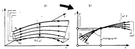
— In three-dimensional flow, the influence of an event is spread over a domain, which is defined by the strength of the skewing of the stream surface, Fig. 7.3. The skin-friction line alone is not representative. Of course also here lateral molecular or turbulent transport happens. If a boundary-layer method is used for the determination of the flow field, it must take into account the domain of dependence of a point P(x, y) on the body surface, which must be enclosed by the numerical domain of dependence, Fig. 7.3 b).

Подпись:

Подпись: skin-friction line ) b.i. streamlines ^ characteristics external streamline; wall normal'—. )

view from above

*p(x»y)

skin-friction 1ine — external stream! ine – . molecule о data known • data to be computed

Fig. 7.3. Three-dimensional boundary layer with the skewed stream surface (schematical) [3]. Note that in this figure x, y are tangential to the surface, and г is normal to it): a) the streamlines as characteristics, b) domains of dependence and of influence of flow properties in P(x, y).

Boundary-Layer Equations

The boundary layer can be considered as the phenomenological model of attached viscous flow. We derive in the following the boundary-layer equa­tions for steady, compressible, three-dimensional flow past a flat surface. We assume laminar flow, but note that the resulting equations also hold for tur­bulent flows, if we treat them as Reynolds – or Favre-averaged flows [1, 6].

The derivation is made in Cartesian coordinates. We keep the notation introduced in Fig. 4.1 with x and z (z not indicated there) being the coor­dinates tangential to the body surface, and y the coordinate normal to it.

Boundary-Layer Equations

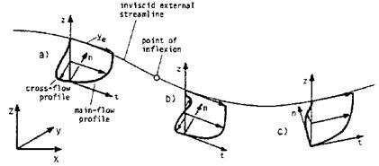
Fig. 7.2. Streamline curvature and cross-flow profiles of a three-dimensional bound­ary layer (schematically) [3]: a) negative cross-flow profile, b) s-shaped cross-flow profile, c) positive cross-flow profile. The coordinates t and n are tangential to the body surface, г is normal to the body surface.

Accordingly u and w are the tangential velocity components, and v is the component normal to the body surface.[86]

We try to keep the derivation as simple as possible in order to concentrate on the basic physical problems. (That is also the reason why we employ Cartesian coordinates.) Therefore, we do not include the description of the typical phenomena connected with hypersonic attached flow like the extra formulations for high-temperature real-gas effects, surface-radiation cooling, and slip-flow effects. Their introduction into the resulting system of equations is straight forward.

The boundary-layer equations are derived from the Navier-Stokes equa­tions, together with the continuity equation and the energy equation, Sub­Section 4.3. They cannot be derived from first principles [1]. One has to intro­duce the observation—the boundary-layer assumption, originally conceived by L. Prandtl [7]—that the extension of the boundary layer in direction normal to the body surface (coordinate y and the involved boundary-layer thicknesses) is very small, like also the velocity component v in the boundary layer normal to the body surface. Actually the observation is that the differ­ent boundary-layer thicknesses and v in y-direction are inversely proportional to the square root of the Reynolds number.

Boundary-Layer Equations Подпись: (7.1) (7.2)

We take care of this observation by introducing the so-called boundary – layer stretching, which brings y and v, non-dimensionalized with reference data Lref and vref, respectively, to O(1):

Reref = Preft’re/Lre/ . (7.3)

ftref

The prime above denotes variables, which were non-dimensionalized and stretched, however, we use it in the following also for variables, which are only non-dimensionalized.

All other variables are simply made dimensionless with appropriate refer­ence data, and assumed then to be O(1): velocity components u and w with vref, lengths x and z with Lref, temperature T with Tref, density p with pref, pressure p with prefv? ff, the transport coefficients /л and к with /i, ref and kref, respectively, and finally the specific heat at constant pressure cp with cPref.4 Each resulting dimensionless variable is marked by a prime, for instance

u’ = —. (7.4)

vref

We introduce boundary-layer stretching and non-dimensionalization first into the continuity equation, eq. (4.83). We do this for illustration in full detail. In three dimensions and without the partial time derivative, Section 4.1, we replace и with u’vref, eq. (7.4), v with v’vrefjjReref, eq. (7.2), etc, and find

df/prefu’vref ^ dp’prefv’yref/-sjReref ^ dp’pref w’vref _ 0 ^ ^

Ox Lref dy’Lref/ уReref k)z Lrej

Because all reference parameters, and also Reref are constants, we find immediately the stretched and dimensionless continuity equation which has the same form—this does not hold for the other equations—as the original equation:

4 In classical boundary-layer theory the pressure is made dimensionless with Pref v2ref, which has the advantage that the equations describe in this form both compressible and incompressible flows. For general hypersonic viscous flows, how­ever, we choose pref to make the pressure dimensionless, Sub-Section 7.1.7.

Boundary-Layer Equations Подпись: + Boundary-Layer Equations

Again we introduce non-dimensional and stretched variables, as we did above. We also write explicitly all terms of O(1), and bundle together all terms, which are of smaller order of magnitude, now except for two of the heat-conduction terms:and Eref the reference Eckert number:

Eref = (jref — l)Mref ■ (7.22)

(Both were introduced in Sub-Section 4.3.2.)

We have retained on purpose in this equation two terms, which are nom­inally of lower order of magnitude. They are the gradients of the heat – conduction terms in x and z direction, which are of O(l/Reref). The reason is that we in general consider radiation-cooled surfaces, where we have to take into account possible strong gradients of Tw in both x and z direction. They appear there on the one hand, because the thermal state of the surface changes strongly in the down-stream direction, usually the main-axis direc­tion of a flight vehicle, Chapter 3. On the other hand, strong changes are present in both x and z direction, if laminar-turbulent transition occurs, see, e. g., Sub-Section 7.3.

Подпись: dy V dy Boundary-Layer Equations Подпись: (7.23)

The question now is, under what conditions can we drop the two terms, regarding the changes of the wall temperature. To answer it, we follow an argumentation given by Chapman and Rubesin [10]. We consider first (in two dimensions) the gradient of the heat-conduction term in direction normal to the surface in dimensional and non-stretched form, eq. (7.19), and introduce finite differences, as we did in Sub-Section 3.2.1:

with 5T being the thickness of the thermal boundary layer.

Boundary-Layer Equations
The gradient of the heat-conduction term in x-direction is written, as­suming that (dT/dx)w is representative for it

The result is: provided, that eq. (7.26) holds, the gradient term of heat conduction in ж-direction can be neglected, because St/L ос 1/(/Pr/Re) ^ 1 in general means

Подпись: (7.28)d dT d dT

« Ж,(к 17’■

In [10] it is assumed, that the recovery temperature is representative for the wall temperature

Tw=Tr= TU1 + г^-ІАф. (7.29)

Boundary-Layer Equations Подпись: (7.30)

Introducing this into eq. (7.26), together with St ~ S « cL/^/Reref for laminar flow, we obtain

With r = y/Pr = a/0.72, Y = 1.4, c = 6 we arrive finally, after having in­troduced non-dimensional variables, at the Chapman-Rubesin criterion [10]. It says that the term eq. (7.24) can be neglected, if

dT’

— |ш ^ <U>3.l/:( x H,,. (7.31)

This means, that, for instance, for M^ = 1 and Reref = 106, the max­imum permissible temperature gradient would be equivalent to a thirty-fold increase of T/T^ along a surface of length Lref. From this it can be con­cluded, that in general for high Mach-number and Reynolds-number flows the Chapman-Rubesin criterion is fulfilled, as long as the surface-temperature distribution is “reasonably smooth and continuous”. The situation can be different for low Mach numbers and Reynolds numbers.

With radiation-cooled surfaces, as we noted above, we do not necessarily have reasonably smooth and continuous surface-temperature distributions in both x and z direction. Moreover, the basic relation eq. (7.23) needs to be adapted, because it does not describe the situation at a radiation-cooled surface. For that situation we introduce a slightly different formulation for both directions:

Подпись: dT < TT Tr — Tw dx w Sj1 dT < TT Tr — Tw dz w Sj1 (7.32)

(7.32) because, at least for laminar flow, Tr — Tw is the characteristic tempera­ture difference, see Sub-Section 3.2.2. We also introduce the absolute values dT/dxw and dT/dzw, because the gradients will be negative downstream
of the forward stagnation point, Sub-Section 3.2.1, but may be positive or negative in laminar-turbulent transition regimes, Sub-Section 7.3, and in hot­spot and cold-spot situations, Sub-Section 3.2.4.

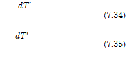
The modified Chapman-Rubesin criterion is then: if eqs. (7.32) and (7.33) hold, the gradient term of heat conduction in both x and ^-direction can be neglected, because again St/L ос 1/(/Pr/Re)

Подпись:Подпись:Подпись: dT'Подпись:__L___ d_

Reref dx’

1 d ‘ Reref dz

We refrain to propose detailed criteria, like the original Chapman-Rubesin criterion, eq. (7.31). This could be done for the region downstream of the forward stagnation point, but not in the other regimes. In practice the results of an exploration solution should show, if and where the modified Chapman- Rubesin criterion is violated or not and whether the two tangential heat conduction terms must be kept or not.[87]

Provided that the modified Chapman-Rubesin criterion is fulfilled, we arrive at the classical boundary-layer equations by neglecting all terms of O(1/Reref) and O(1/Re2ref) in eqs. (7.6), (7.16) to (7.18), and (7.20). We write the variables without prime, understanding that the equations can be read in either way, non-dimensional, stretched or non-stretched, and dimen­sional and non-stretched, then without the similarity parameters Prref and

Eref :

dpu dpv

dx dy

g о c§" ^

+

= 0,

(7.36)

du

du

du

dp

d

f du

(7.37)

fmd~x

+ ,n% +

PWTz

dx

+ % 1

V%) ’

0 = –

dp

dy’

(7.38)

dw

dw

dw

dp

d

f dw

(7.39)

PU^

+ ""% +

pwlb

dz

+ dy

Ы) ’

du 2 / dw 2 1

dy) +dy) j

Boundary-Layer Equations
Подпись: +
Подпись: (7.40)

These equations are the ordinary boundary-layer equations which describe attached viscous flow fields on hypersonic flight vehicles. If thick boundary layers are present and/or entropy-layer swallowing occurs, they must be em­ployed in second-order formulation, see below. For very large reference Mach numbers Mref the equations become fundamentally changed, see Sub-Section 7.1.7.[88]

With the above equations we can determine the unknowns u, v, w, and T. The unknowns density p, viscosity p, thermal conductivity k, and specific heat at constant pressure cp are to be found with the equation of state p = pRT, and the respective relations given in Chapters 4 and 5. If the boundary – layer flow is turbulent, the apparent transport properties must be introduced, [1] and Section 8.5. If high-temperature real-gas effects are present in the flow field under consideration, the respective formulations and laws must be incorporated.

Since dp/dy is zero, the pressure field of the external inviscid flow field, represented by dp/dx and dp/dz, is imposed on the boundary layer. This means, that in the boundary layer dp/dx and dp/dz are constant in y – direction. This holds for first-order boundary layers. If second-order effects are present, dp/dx and dp/dz in the boundary layer are implicitly corrected via dp/dy = 0 by centrifugal terms, see below.

The equations are first-order boundary-layer equations, based on Carte­sian coordinates. In general locally monoclinic surface-oriented coordinates, factors and additional terms are added, which bring in the metric proper­ties of the coordinate system [1]. It should be noted, that the equations for the general coordinates are formulated such that also the velocity com­ponents are transformed. This is in contrast to modern Euler and Navier – Stokes/RANS methods formulated for general coordinates. There only the geometry is transformed, Section A, and not the velocity components.

If locally the boundary-layer thickness is not small compared to the small­est radius of curvature of the surface, the pressure gradient in the boundary layer in direction normal to the surface, dp/dy, is no longer small of higher order, and hence no longer can be neglected.[89] This is a situation found typically in hypersonic flows, where also entropy-layer swallowing can oc­
cur, Sub-Section 6.4.2. This situation is taken into account by second-order boundary-layer equations, which basically have the same form as the first – order equations [1, 12]. Information about the curvature properties of the surface is added. The y-momentum equation does not degenerate into dp/dy = 0. dp/dy is finite because centrifugal forces have to be taken into account. At the outer edge of the boundary layer the boundary conditions are deter­mined by values from within the inviscid flow field, not from the surface as in first-order theory, see the discussion in Sub-Section 6.4.2. Also the first derivatives of the tangential velocity components, of temperature, density and pressure are continuous [12], which is not the case in first-order theory, see, e. g., Fig. 6.23.

Some Properties of Three-Dimensional Attached Viscous Flow

To apply a simplification or an approximation makes only sense, if the real situation is sufficiently known. Therefore we consider now some properties of attached viscous flow, i. e., three-dimensional boundary layers. For a general introduction to three-dimensional attached viscous see [1]. No comprehensive description of separated and vortical flows is available. We refer the reader in this respect to, e. g., [2]-[5].

A three-dimensional boundary layer is governed by the two-dimensional external inviscid flow at or very close to the surface of the body. This exter­nal inviscid flow is two-dimensional in the sense that its streamlines are—to different degrees—curved tangentially to the body surface. As a consequence of this curvature locally all boundary-layer streamlines are stronger curved than the external streamline [1]. The skin-friction line, finally, thus can have quite another direction than the external inviscid streamline. In practice this means, that, for instance, the surface oil-flow pattern on a wind-tunnel model is not necessarily representative for the pattern of the external inviscid flow field close to surface.

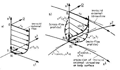
A stream surface, i. e., a boundary-layer profile, in a three-dimensional boundary layer defined in direction normal to the body surface, will be­come skewed in downstream direction due to the different curvatures of its streamlines. This is in contrast to a two-dimensional boundary layer, where the stream surface keeps its shape in the downstream direction. Hence the boundary layer profiles look different in the two cases, Fig. 7.1 a) and b).

If in a three-dimensional boundary layer on an arbitrary body surface the coordinate system locally is oriented at the external stream line, we call it a locally monoclinic orthogonal external-streamline oriented coordinate system [1].[85] In such a coordinate system the skewed boundary-layer profile can be decomposed into the main-flow profile and the cross-flow profile, Fig. 7.1 b). The main-flow profile resembles the two-dimensional profile, Fig. 7.1 a). The cross-flow profile by definition has zero velocity v*2 = 0 at both the surface, x3 = 0, and the boundary-layer edge, x3 = S.

Some Properties of Three-Dimensional Attached Viscous Flow

Fig. 7.1. Wall-near viscous part of the stream surface, schematics of boundary- layer profiles [1]: a) two-dimensional flow (not skewed), b) three-dimensional flow (skewed). External inviscid streamline-oriented coordinate systems: x1 and x2 are the surface-tangential coordinates with v*1(x3) and v*2(x3) the related stream-wise (main-flow) and cross-flow viscous-flow profiles, x3 is the surface-normal coordinate. The resulting velocity profile in the 3-D case is v(x3). Q_ is the vector of vorticity content of the boundary layer [5].

The cross-flow profile, however, changes its shape, if the external inviscid streamline changes its curvature in the plane tangential to the body surface. Then an s-shaped profile will appear in the region just behind the inflection point of the external streamline, and finally an orientation of the profile in the opposite direction, Fig. 7.2.

Attached Viscous Flow

7.1.1 Attached Viscous Flow as Flow Phenomenon

The flow past a body exhibits, beginning at the forward stagnation point, a thin layer close to the body surface, where viscous effects play a role. They are due to the fact that the fluid in the continuum regime fully sticks to the surface: no-slip boundary condition, eq. (4.47), or—in the slip-flow regime— only partly: slip-flow boundary condition, eq. (4.48). In these cases we speak about attached viscous flow. Away from this layer the flow field is inviscid, i. e., viscous effects can be neglected there. Of course the inviscid flow field behind the flight vehicle, and at large angle of attack also above it, contains vortex sheets and vortices, which are viscous phenomena, together with shock waves, Section 6.1.

Attached viscous flow must always be seen in connection with the flow past the body as a whole. The body surface with either no-slip or slip boundary condition, together with the thermal and thermo-chemical boundary condi­tions, Section 4.3, is the causa prima for that flow. If the layer of attached viscous flow is sufficiently thin, the flow in it is nearly parallel to the body surface and the gradient of the pressure in it in direction normal to the sur­face vanishes. Attached viscous flow in this case is governed by the pressure field of the external inviscid flow field, and, of course, its other properties, and the surface boundary conditions. We call such an attached viscous flow sheet a “boundary layer”.[84] The boundary layer can be considered as the phe­nomenological model of attached viscous flow [1]. In the following we use the terms “attached viscous flow” and “boundary layer” synonymously.

Of special interest in flight vehicle design are the (flow) boundary-layer thicknesses S, the thickness of the viscous sub-layer Svs, the displacement thickness S1, the wall shear stress tw, and the thermal state of the surface, which encompasses both the wall temperature Tw and the heat flux in the gas at the wall qgw. All for laminar and for turbulent flow. They will be discussed in detail in the following sections.

For these discussions we assume in general two-dimensional boundary – layer flows. In reality the flows past hypersonic flight vehicles are three­dimensional, see, e.g., Figs. 7.8, 7.9, and 9.5. However, large portions of the flow can be considered as quasi two-dimensional, and can be treated, with due caution, with the help of two-dimensional boundary-layer models, for instance for initial qualitative considerations, and for the approximate determination of boundary-layer parameters. This does not hold in regions with attachment and separation phenomena etc. [1], which, for example, are present in flight at high angle of attack, Fig. 9.5.

Attached High-Speed Viscous Flow

At the beginning of Chapter 6 we have noted that in the hypersonic flight regime, like in the lower speed flight regimes, flow fields can be separated into inviscid and viscous portions. At high altitudes this separation may become questionable. However, the central topic of this chapter is attached high­speed viscous flow, whose basic properties are described with the help of the phenomenological model “boundary layer”.

We look first at the typical phenomena arising in viscous flows and their consequences for the aerothermodynamic vehicle design. Attached viscous flow is characterized, in general, by the molecular transport of momentum, energy and mass, Chapter 4, towards the vehicle surface, with wall-shear stress, the thermal state of the surface, thermo-chemical wall phenomena, etc., as consequences. We treat the boundary-layer equations, consider their limits in hypersonic flow, examine the implications of radiation cooling of vehicle surfaces, and define integral properties and surface parameters, in­cluding viscous thermal-surface effects. (Examples of viscous thermal surface effects were given in some of the preceding chapters. More are collected and discussed in Chapter 10.)

Finally we give simple relations for laminar and turbulent flow—with ex­tensions to compressible flow by means of the reference temperature/enthalpy concept—for the estimation of boundary-layer thicknesses, wall-shear stress, and the thermal state of a surface (wall heat flux and wall temperature) for planar surfaces, spherical noses and cylindrical swept edges. A case study closes the chapter.

Laminar-turbulent transition and turbulence in attached viscous flow, which we have to cope with at altitudes below approximately 40 to 60 km, are considered in Chapter 8. We discuss there the basic phenomena, their dependence on flow and surface parameters, and on the thermal state of the surface. The state of the art regarding transition prediction and turbulence models is also reviewed.

(C Springer International Publishing Switzerland 2015 E. H. Hirschel, Basics of Aerothermodynamics,

DOI: 10.1007/978-3-319-14373-6 _7

Connected too to viscous flow are the flow-separation phenomenon and other strong-interaction phenomena. In Chapter 9 we treat separation and the typical supersonic and hypersonic strong interaction phenomena in­cluding hypersonic viscous interaction, and finally rarefaction effects, which are related to the latter phenomenon. All these phenomena are of large importance in aerothermodynamic design, because they may influence not only performance, flyability and controllability of a flight vehicle, but also, and that very strongly, the thermal and mechanical loads on the airframe and its components.

The Mach-Number Independence Principle of Oswatitsch

We have found in Sub-Sections 6.3.1 and 6.3.2 that for M^ to velocity components, density, Mach number and pressure coefficient behind normal and oblique shocks, and hence behind a bow-shock surface, become indepen­dent of MTO.

We consider now the situation behind a bow-shock surface, for conve­nience only in two dimensions. We use the notation from Fig. 6.9 for the Cartesian velocity components behind a shock surface. We replace in eqs. (6.111) to (6.113), (6.70), (6.103), and (6.105) the subscript 1 with to, write

Подпись: 2

parameters non-dimensionalized with their free-stream parameters[77]

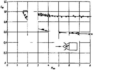
Experimental observations, and these relations have led to what we call Oswatitsch’s Mach number independence principle.[78] In his original work, [44], Oswatitsch defines flow at very large Mach numbers M ^ 1 as hy­personic flow, see also [22]. All flows at large Mach numbers have already hypersonic properties in the sense that certain force coefficients become in­dependent of the Mach number. This happens, depending on the body form, already for free-stream Mach numbers as low as Mto = 4 to 5, see for instance Fig. 6.40.[79]

For practical purposes we hence can say that Mach number independence is given, if for a given body in a steady free stream the shape of the bow-shock surface, the streamline pattern, the sonic surface, the Mach lines (character­istics) in the supersonic part of the flow field, the pressure coefficient, as well as the force and moment coefficients asymptotically become Mach number independent. This holds for inviscid perfect gas flow. Below we will come back to the principle for the cases of viscous and high-temperature real-gas flows.

We consider here in particular the case of blunt bodies. This relates mainly to RV’s, but also to high flight Mach number CAV’s, which always have a

The Mach-Number Independence Principle of Oswatitscho — Charters and Thomas ft — Hodges • — Stevens x ■= Naumann
nose with finite bluntness in order to withstand the thermal loads at large flight speeds.

The shape of the bow-shock surface is governed by the body shape and the free-stream parameters. The flow properties just behind the bow-shock surface are the upstream boundary conditions for the flow past the body. For Mж ^ ж they are those given in eqs. (6.168) to (6.171). They are functions of the shape of the bow-shock surface, i. e., the shock angle в, and the ratio of specific heats 7.

In the following we consider still only the two-dimensional case. This suffices completely to show the essence of the Mach-number independence principle. The derivation of the general three-dimensional case is straight forward.

We derive first the gasdynamic equation. We consider steady inviscid flow of a perfect gas. We re-formulate the pressure-gradient terms of the Euler equations—in two dimensions eqs. (4.27) and (4.28) without the molecular and mass-diffusion transport terms—with the speed of sound, eq. (6.8)

Подпись:dp = dP = °2dp-

We combine now the Euler equations with the continuity equation eq. (4.83), neglect the time derivatives, and find the gasdynamic equation in two-dimensional Cartesian coordinates

dv

— + uv dy
du dv dy dx

Together with Crocco’s theorem

V x rotV_= — T grads, (6.176)

we have three equations for the determination of u, v, and the entropy s.

To eliminate the speed of sound a and the temperature T we use eq. (6.14). We rewrite that equation and find with V2 = u2 + v2 (see Fig. 6.9):

The Mach-Number Independence Principle of Oswatitsch

The question is whether indeed the terms with 1/M2 can be omitted, because at slender bodies V « иж, and hence 1 — (V2/u2) is small, too. It is argued that V/uж depends only on the shock angle of the bow shock, eq. (6.170), and not on Мж [44]. Therefore eqs. (6.180) and (6.179) are suf­ficiently exact, as long as Мж is sufficiently large.

It remains the problem to express in eq. (6.176) the entropy s for Мж ^ ж. From eq. (6.79) for the normal shock surface we gather that in this case s ^ ж, which also holds for an oblique shock surface. This problem is circumvented by introducing the difference s’ = soblique shock – Snormal shock:[80]

2y cv

These equations describe the flow between the bow-shock and the body surface. They are supplemented by the boundary conditions behind the bow – shock surface, eqs. (6.168), (6.169) (6.182), and the boundary conditions at the body surface. The latter are kinematic conditions, which demand vanish­ing of the flow-velocity component normal to the body surface, i. e., the flow to be tangential to it.

The system of equations is independent of the free-stream Mach number MTO. Assuming uniqueness, we deduce from it that u’, v’ and s’ in the flow field between bow-shock surface and body surface do not depend on MTO, but only on the body shape, and the ratio of specific heats y. This holds also for the shape of the bow-shock surface, and the pattern of the streamlines, the sonic line, and the Mach lines in the supersonic part of the flow field. Density p’, eq. (6.171) and pressure coefficient cp, eq. (6.173), and with the latter the force and moment coefficients, are also independent of MTO.[81]

Oswatitsch called his result a similarity law. In [22] it is argued that to call it “independence principle” would be more apt, because it is a special type of similitude, being stronger than a general similitude. It is valid at the windward side of a body, i. e., in the portions of the flow past a body, where the bow-shock surface lies close to the body surface, see, e. g., Fig. 6.22 b). It is not valid at the leeward side of a body, where, due to the hypersonic shadow effect, only small forces are exerted on the body surface. Nothing is stated about transition regimes between windward side and leeward side surface portions.

In [44] no solution of the system of equations (6.183) and (6.184) is given. A recent solution can be found in [45]. In [22] several theories are discussed, some of which base directly on the findings of Oswatitsch. We have used results of two of these theories in Sub-Section 6.4.1 to discuss the influence of high-temperature real-gas effects on the bow-shock stand-off distance at a blunt body.

Oswatitsch’s independence principle is an important principle for applied aerothermodynamics. If we obtain for a given body shape experimentally for instance the force coefficients at a Mach number M^ large enough, they are valid then for all larger Mach numbers Mo > M^, Fig. 6.40, provided, however, that we have perfect-gas flow.[82] In [22] it is argued that Oswatitsch’s independence principle also holds for non-perfect gas flow. In any case we can introduce an effective ratio of specific heats Yef f, and thus study the influence of high-temperature real-gas effects.

In [2] this is made in view of the pitching moment anomaly observed during the first re-entry flight of the Space Shuttle Orbiter. Together with results of solutions of the Euler equations it is shown that obviously a “be­nign” (inviscid) wall Mach number interval exists with Mwau ^ 2.2 in which high-temperature real-gas effects only very weakly violate the Mach number independence principle. Above that wall Mach number it begins to lose its validity.

In [22] it is claimed too, that the principle holds for boundary layers in hypersonic flows, as long as the external inviscid flow follows the independence principle. In [46] results of a numerical study are given which indicate that this holds only in the case of an adiabatic wall and in any case not for a radiation or otherwise cooled wall.

For slender, sharp-nosed bodies at very large Mach numbers Mo the Mach angle /i, o may be of the same order of magnitude as the maximum deflection angle в, which the flow undergoes at the body surface. This class of high Mach number flow is characterized by the hypersonic similarity parameter, see, e. g., [4, 6]

K = Mo sin в ^ 1, (6.185)

which was introduced by Tsien [47].[83]

In terms of the thickness ratio т (body thickness/body length) of such bodies it reads

K = Mot > 1. (6.186)

Not going into details of the theory we note the results [4, 44], which are important for aerodynamic shape definition:

— the surface pressure coefficient of a body with thickness ratio т follows

cp ж т2, (6.187)

— and the wave drag coefficient

CDw ж т3. (6.188)

It can be expected that these results give also the right increments in the case of slender, blunt-nosed configurations at small angle of attack, i. e., CAV’s. Of course at a blunt nose (the nose bluntness is the major driver of the wave drag) the pressure coefficient is not covered by the relation (6.187).

Modification Schemes, Application Aspects

We have noted above, that already at free-stream Mach numbers above Мж « 3 to 4 useful results can be achieved with Newton’s theory. However, for both the flat plate and the sharp-nosed cone results of Newton’s theory lie somewhat below exact results, as long as we have finite Mach numbers and realistic ratios of specific heats. What about the situation then at generally shaped, and in particular blunt-nosed bodies?

Two modification schemes to the original formulation have been proposed. The first is Busemann’s centrifugal correction [39, 22], which, however is not very effective.

The second scheme is important especially for blunt-nosed bodies. In [40] it is observed from experimental data, that for such bodies a pressure co­efficient, corrected with the stagnation-point value cPmax, gives satisfactory results for Мж ^ 2.

With cPmax = cPt2 for the stagnation point, eq. (6.65), writing pe for the pressure on the body surface, respectively the boundary-layer edge, and using

Modification Schemes, Application Aspects

Modification Schemes, Application Aspects

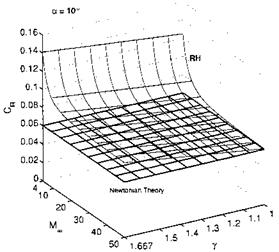
Fig. 6.36. The total force coefficient CR at the windward side of a flat plate (RHPM-flyer) at a = 10° found with eq. (6.150) (Newtonian Theory, constant value, lower surface), and eq. (6.98) (exact (RH), upper surface), for 4 A MA 50, and 1 A 7 A 1.666 [1].


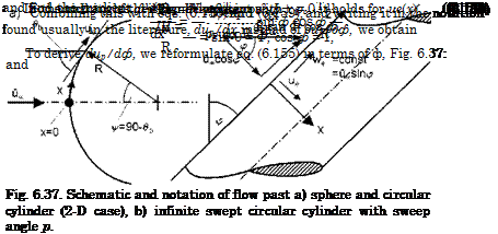
вь, Fig. 6.37, for the local body slope, instead of a, we find the “modified” Newton relation

This modified Newton relation, in contrast to the original one, depends on the free-stream Mach number MTO.

For the investigation of boundary-layer properties, Section 7.2, at the stagnation point of blunt bodies or at the attachment line of blunt swept leading edges etc., we need the gradient of the external inviscid velocity ue there.

Assuming either a spherical or a cylindrical contour, Fig. 6.37 a), we find for both of them, see, e. g., [41], the Euler equation for the ф direction:

Подпись: 1 dpe R дф '1 due

peUeR~W

Modification Schemes, Application Aspects
At the stagnation point it holds

Modification Schemes, Application Aspects Modification Schemes, Application Aspects Подпись: (6.164)

and hence

Подпись: due dx Modification Schemes, Application Aspects Подпись: 2(ps -p,x) x 1 psx R R Подпись: x=0 Подпись: (6.165)

We substitute now ue in eq. (6.162) with the help of eq. (6.164) and q with the help of eq. (6.160), and find with eqs. (6.158) and (6.159)

where ps and ps are pressure and density in the stagnation point. Note that cp did cancel out.

pmax

Подпись: due ~cb'x=0 Подпись: _fc /2(ps -p,x) R Ps Подпись: (6.166)

The gradient of the inviscid velocity at the stagnation point in x – direc­tion, Fig. (6.37), finally is

This result holds, in analogy to potential theory, with к = 1 for the sphere, and к = 1.33 for the circular cylinder (2-D case), and for both Newton and modified Newton flow.[76]

At the infinite swept cylinder with sweep angle p, it is the component of the free-stream vector normal to the cylinder axis, ucos p, Fig. 6.37 b), which matters. It can be written in terms of the unswept case and cos p:

Подпись: 1-33 2(ps -Pco) R  PsПодпись: due ./ "- r - >n = cos p . (6.167)

^ = 0

The important result in all cases is that the velocity gradient due/dx at the stagnation point or at the stagnation line, is ж 1/R. The larger R, the smaller is the gradient. At the attachment line of the infinite swept cylinder it reduces also with increasing sweep angle, i. e., due/dxlx=0,v>0 ж cosp/R.

We note finally that recent experimental work has shown, that the above result has deficiencies, which are due to high-temperature real-gas effects [43]. With increasing density ratio across the shock, i. e., decreasing shock stand-off distance, Sub-Section 6.4.1, due/dxlx=0 becomes larger. The increment grows nearly linearly up to 30 per cent for density ratios up to 12. If due/dxlx=0 is needed with high accuracy, this effect must be taken into account.

We can determine now, besides the pressure at the stagnation point and at the body surface, also the inviscid velocity gradient at the stagnation point or across the attachment line of infinite swept circular cylinders. With the relations for isentropic expansion, starting from the stagnation point, it is possible to compute the distribution of the inviscid velocity, as well as the temperature and the density at the surface of the body. With these data, and

with the help of boundary-layer relations, wall shear stress, heat flux in the gas at the wall etc. can be obtained.

This is possible also for surfaces of three-dimensional bodies, with a step­wise marching downstream, depending on the surface paneling [34]. Of course, surface portions lying in the shadow of upstream portions, for example the upper side of a flight vehicle at angle of attack, cannot be treated. In the ap­proximate method HOTSOSE [34], the modified Newton scheme is combined with the Prandtl-Meyer expansion and the oblique-shock relations in order to overcome this shortcoming.

However, entropy-layer swallowing cannot be taken into account, because the bow-shock shape is not known. Hence the streamlines of the inviscid flow field between the bow-shock shape and the body surface and their entropy values cannot be determined.

This leads us to another limitation of the modified Newton method. It is exact only if the stagnation point is hit by the streamline which crossed the locally normal shock surface, Fig. 6.22 a). If we have the asymmetric situation shown in Fig. 6.22 b), we cannot determine the pressure coefficient in the stagnation point, because we do not know where Pi lies on the bow – shock surface. Hence we cannot apply eq. (6.99). In such cases the modified Newton method, eq. (6.155), will give acceptable results only if Pi can be assumed to lie in the vicinity of Pq.

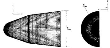
We discuss finally a HOTSOSE result for the axisymmetric biconic re­entry capsule shown in Fig. 6.38.

Modification Schemes, Application Aspects

Fig. 6.38. Configuration and HOTSOSE mesh of the biconic re-entry capsule (BRC) [34].

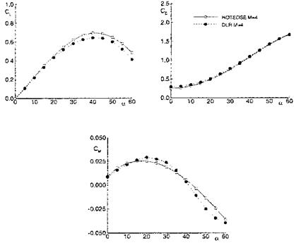
The scheme was applied for free-stream Mach numbers = 4 to 10 and the large range of angles of attack 0 ^ a ^ 60°. We show here only the results for Mж = 4, which are compared in Fig. 6.39 with Euler results.

The lift coefficient Cl found with HOTSOSE compares well with the Euler data up to a & 20°. The same is true for the pitching-moment coefficient Cm. For larger angles of attack the stagnation point moves away from the spherical nose cap and the solution runs into the problem that Pi becomes different from Pq, Fig. 6.22 b). In addition three-dimensional effects play a role, which

Modification Schemes, Application Aspects

Fig. 6.39. Aerodynamic coefficients (inviscid flow, perfect gas) for the biconic re­entry capsule at Mo = 4 obtained with HOTSOSE (o) and compared with Euler results (•) [34]. Upper part left: lift coefficient Cl, upper part right: drag coefficient Cd, lower part: moment coefficient Cm.

are not captured properly by the scheme if the surface discretization remains fixed [34]. The drag coefficient Cd compares well for the whole range of angle of attack, with a little, inexplicable difference at small angles.

Newton Flow

6.7.1 Basics of Newton Flow

At flight with very large speed, respective Mach number, the enthalpy hof the undisturbed atmosphere is small compared to the kinetic energy of the flow relative to the moving flight vehicle. The relation for the total enthalpy, eq. (3.2), can be reduced to

M, x – T oo : ht = (6.143)

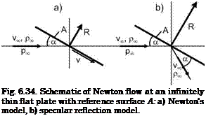
If we neglect the flow enthalpy also in the flow field at the body surface, the forces exerted on the body would be due only to the kinetic energy of the fluid particles. A corresponding mathematical flow model was proposed by I. Newton [22]. His model assumes that the fluid particles, coming as a
parallel stream, hit the body surface, exert a force, and then move away parallel to the body surface, Fig. 6.34 a). With the notation given in that figure, we obtain for the force R* acting on an infinitely thin flat plate with the reference surface A

Подпись: 23R* = pv2 sin2 aA. (6.144)

Подпись: Fig. 6.34. Schematic of Newton flow at an infinitely thin flat plate with reference surface A: a) Newton’s model, b) specular reflection model.

This is in contrast to specular reflection, Fig. 6.34 b) (free-molecular flow), which would lead to a force twice as large. However, case a) models surpris­ingly well the actual forces in the continuum flow regime.

If we also take into account the ambient pressure pTO, we get the aerody­namic force acting on the windward side of the flat plate

R = (provj^ sin2 a + p^)A. (6.145)

Подпись: CPws Подпись: P-Poo Qoo Подпись: 1 R 2 — (yr -Poo) = 2sin- a. A Подпись: (6.146)

The surface-pressure coefficient on the windward side, cPws, then is

Подпись: CPls Подпись: 0. Подпись: (6.147)

On the leeward side of the flat plate only the ambient pressure acts, p = pro, because this side is not hit by the incoming free-stream.[75] The surface – pressure coefficient on this side, cPls, hence is

With the usual definitions we find the lift and the drag coefficient for the infinitely thin flat plate

Подпись: (6.148)CL = (cPws — cpis) cos a = 2 sin2 a cos a,

and

CD = (cPws — cpis) sin a = 2 sin3 a. (6.149)

The resulting force coefficient has the same value as the pressure coeffi­cient on the windward side:

CR = (cPws — cpis) = 2 sin2 a. (6.150)

These relations obviously are valid only for large Mach numbers. Take for instance an airfoil in subsonic flow. Its lift at angles of attack up to approximately maximum lift is directly proportional to the angle of attack a, and not to cos a sin2 a.

Newton’s model is the constitutive element of “local surface inclination” or “impact” methods for the determination of aerodynamic forces and even flow fields at large Mach numbers. In design work, especially with incremental approaches, it can be used down to flight Mach numbers as low as Ыж « 3 to 4 [38].

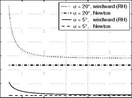
If we compare pressure coefficients at the windward side of an infinitely thin flat plate at angle of attack, the RHPM-flyer [1], we find at all angles of attack a, that the Newton value is below the exact value, Fig. 6.35, where results for two angles of attack are given. The difference increases with in­creasing a, and decreases with increasing MTO.

Подпись: 0.6 0.5 Подпись: 0.4 CE О 0.3 Подпись: 0.2 0.1 Подпись: 0 5 10 15 20 25 30 мя Подпись:Newton Flow0.7

0

The exact (RH = Rankine Hugoniot) value obviously becomes “Mach- number independent” (Section 6.8) for Ыж ^ 8. For a sharp-nosed cone Mach-number independence is found already at Ыж ^ 4, and the Newton result lies closer to, but still below, the exact result.

Certainly there is a physical meaning behind Newton’s model. It is Mach – number independent per se, and the difference to the exact value becomes smaller with decreasing ratio of specific heats 7. We find an explanation, when we reconsider the pressure coefficient behind the oblique shock for very large Mach numbers, eq. (6.105)

, ^ 4sin2 в. _ _.

M, x -> 00 : Cp у————- —, (6.151)

Y +1

and also the relation between the shock angle в and the ramp angle S for very large Mach numbers, eq. (6.117)

Y +1

Moo —> 00 : в —> —-—S. (6.152)

For y ^ 1 we obtain that the shock surface lies on the ramp surface (infinitely thin shock layer):

в ^ S, (6.153)

and hence

cp ^ 2sin2 S. (6.154)

Since the ramp angle S is the angle of attack a of the flat plate, we have found the result, see eq. (6.146), that in the limit Мж ^ ж, and y ^ 1, Newton’s theory is exact. This is illustrated in Fig. 6.36, where with increasing Mach number and decreasing ratio of specific heats finally the exact solution meets Newton’s result.

The Change of the Unit Reynolds Number across Shock Waves

We have seen that the shock angle в of a bow-shock surface decreases from 90° at its normal shock portion asymptotically to the Mach angle pTO, which corresponds to the free-stream Mach number MTO. At a two-dimensional su­personic compression ramp, which represents either a hypersonic inlet ramp, or is the approximation of a trim or control surface, we have—if we neglect viscous effects—shock angles, which for perfect gas are functions of the onset or free-stream Mach number Mi (= MTO), the ratio of specific heats 7, and the ramp angle S only. Eq. (6.114) connects these entities.

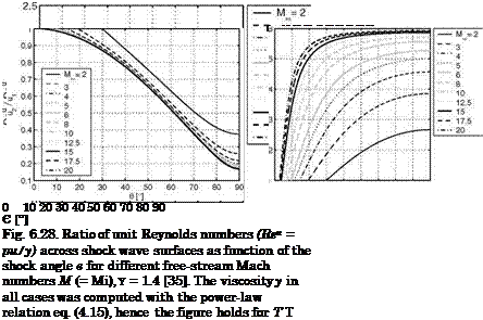
We consider a plane oblique shock surface at shock angles 90° > в > рж regardless of the geometry that is inducing it. We ask how the unit Reynolds number Reu is changing across the shock wave, Fig. 6.28. The unit Reynolds number governs the properties of a boundary layer. If it increases across the shock wave, behind it the thickness of the boundary layer, the displacement thickness and the other ones, are reduced, the heat flux in the gas at the wall, the radiation-cooling temperature and the skin friction are increased, see Section 7.2.

We observe in Fig. 6.28 first, that for в = 90° at all Mach numbers M1 > 1 the unit Reynolds number Reu behind the shock (2) is smaller than ahead of it (1):

в = 90° : Reu/Reu < 1. (6.142)

This is obvious, because p2u2 = p1u1, and T2 > T1, and hence the viscosity

p2 > p1.

If we now reduce with a given Mach number M1 the shock angle в, we find that the ratio Reu/Reu increases, and that a shock angle exists, below which Reu/Reu > 1. This holds for all Mach numbers and ratios of specific heat [35].

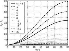
This behavior is due to the fact that u2/u1 increases with decreasing shock angle в, that the density ratio p2/p1 decreases first weakly and then strongly with decreasing в, Fig. 6.29, whereas the temperature ratio T/T decreases first weakly and for small в weakly again, Fig. 6.30.

The Change of the Unit Reynolds Number across Shock Waves

Fig. 6.29. Behavior of u2 /u1 (left) and of p2/p1 (right) as function of the shock angle в and the Mach number Мж (= M1), y = 1.4 [35]. Note that u2 /u1 = V2/V1 in Fig. 6.9.

The behavior of the ratio of the unit Reynolds numbers across shock surfaces is of interest insofar as the development of the boundary layer behind an oblique shock wave, induced for instance by an inlet ramp or a trim or control surface, to a large degree is governed by it [2].

This holds for attached boundary layers, but in principle also at the foot of the shock surface, where strong-interaction phenomena may occur. We un­derstand now that an increase of, for instance, the radiation-adiabatic tem­perature of the body surface behind an oblique shock surface happens only, if the shock angle в is below a certain value, which causes an increase of the unit Reynolds number. Otherwise a decrease will be observed.

The Change of the Unit Reynolds Number across Shock Waves

Fig. 6.30. Behavior of T2/T1 as function of the shock angle в and the Mach number Moo (= Ml), 7 = 1.4 [35].

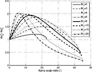
For application purposes it is useful to connect the changes of the unit Reynolds number directly with the ramp angle S. The result is shown in Fig. 6.31. It was made with the same assumptions as the previous figures.

The Change of the Unit Reynolds Number across Shock Waves

Fig. 6.31. Ratio of the unit Reynolds numbers Ref/Ref across the shock wave of a flat-plate (1)/ramp (2) configuration as function of the ramp angle S for different flat-plate Mach numbers M1 and the ratio of the specific heats 7 =1.4 [36].

Look for instance at the curve with the Mach number Mi = 8. For 0° < S < 35° we have ReU 2 > ReU 1, with a maximum around S « 12°. This means that in this interval all boundary layer thicknesses on the ramp (2) will be smaller than those on the flat plate (1). For S > 35°, the opposite is true. For smaller Mach numbers Mi, smaller maximum ramp angles with weaker shock waves are reached, the Reynolds-number ratios and their maxima become smaller, too. Interesting is that for larger Mach numbers the ramp angles decrease, for which the unit Reynolds number ratios become < 1. Then also the maxima are more pronounced, lying around two. High-temperature real gas effects in general increase the maxima of the unit Reynolds number ratios and shift the ratios smaller than one to larger ramp angles [2].

The behavior of the ratio Re^/Re™ is of practical interest. Regarding an aerodynamic trim or control surface, we see that this ratio as function of the deflection angle 5 always has a maximum. The location of this maximum depends on the Mach number Mi. The result is that—for a given Mach number Mi—the surface pressure on the ramp increases with increasing 5, but the ratio ReU/Reu first increases and then decreases, hence thermal loads and skin-friction behave in the same way. They have their maximum at the angle where the ratio has its maximum. This means that thermal and friction loads have a maximum at a certain 5, but that a larger deflection angle not necessarily increases them.

In reality the relevant ratio ReU/Re™ depends on the location on the flight vehicle. In particular we note that ReU is not ReU, but a local one. The behavior of the ratio explains also the always observed stepwise increase of the thermal loads—for instance the radiation-adiabatic temperature Tra—on ramp inlets.

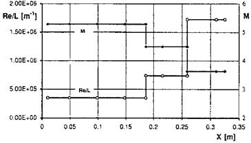
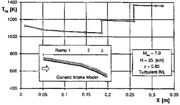
We illustrate this in Figs. 6.32 and 6.33 with results from a study with an approximate method of the flow past a generic three-ramp inlet [37]. The free – stream Mach-number is M^ = 7, the altitude H = 35 km, and the emissivity of the radiation-cooled ramp surfaces £ = 0.85. The flow is considered to be two-dimensional and fully turbulent.

The Change of the Unit Reynolds Number across Shock Waves

Fig. 6.32. Generic two-dimensional inlet model with three outer ramps (for the ramp geometry see Fig. 6.33) [37]: Mach number (M) and unit Reynolds number (Re/L = Reu) on the ramps.

The Change of the Unit Reynolds Number across Shock Waves

Fig. 6.33. Generic two-dimensional inlet model with three outer ramps [37]: radiation-adiabatic temperature Tra on the ramps.

We find in Fig. 6.32 a stepwise reduction of the Mach number, and a stepwise increase of the unit Reynolds number.[74] With the increase of the unit Reynolds number on each ramp the thickness of the boundary layer decreases. Therefore the radiation-adiabatic temperature on each ramp rises stepwise by almost 200 K to a higher level, Fig. 6.33, and then always decreases slightly with the boundary-layer growth, see Sub-Section 3.2.1, on each ramp.