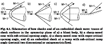
Consider streamline (1) in Fig. 6.1 a). It penetrates the bow-shock surface at a location, where the latter is inclined by approximately 45° against the free-stream direction. The streamline is deflected slightly behind the shock towards the shock surface.
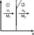
We employ the same reasoning as for the normal shock wave, and define the phenomenological model “oblique shock wave”, which is a plane shock surface, which lies inclined (shock angle 9) to a parallel and uniform supersonic stream. It is induced for example by a ramp with ramp or deflection angle S, Fig. 6.9. The flow is inviscid, and the ramp surface is a streamline. Behind the oblique shock wave the flow is again parallel and uniform,[62] but now it is deflected by S towards the shock surface, Fig. 6.9.
For a shock wave, like for any wave phenomenon, changes of flow parameters happen only in the direction normal to the shock wave. This means that the governing entity at any point of a shock surface is the normal Mach number M1n, i. e., the Mach number of the flow velocity component normal to the shock surface u1 at that point, Fig. 6.9:
u Vi sin9 ,, . „ .
MN = — = ————– = Msin6. (6.81)
The shock relations (again for perfect gas) are in principle the same as those for the normal shock, only that now Ui1 replaces u. Prandtl’s relation now reads
uyui = a2 – А“Тг~’2’ (6.82)
у + 1
where V is the component of Vi tangential to the oblique shock wave, Fig. 6.9, which does not change across it[63]
V = Vi = v>2 = VicosO. (6.83)
The Rankine-Hugoniot relations are identical to those for the normal shock wave.
We give now, as we did for the normal shock, some relations for the change of the flow parameters across the oblique shock, Fig. 6.9, in terms of the upstream Mach number M1, the shock-inclination angle O, and the ratio of specific heats у, again see, e. g., [11]:
We can at once take over qualitatively the results for the normal shock wave, when we deal with an oblique compression shock. This means that also across the oblique shock pressure p, density p, temperature T are increasing instantly, whereas speed V decreases instantly. The important difference is, that we get subsonic flow behind the shock too, but only for the flow component normal to the shock surface:
M2n oblique shock < 1 (OOO)
Then the question arises, whether the resultant flow behind the oblique shock is subsonic or supersonic, i. e., whether the Mach number M2 = V2/a2 < 1 (strong shock wave) or > 1 (weak shock wave). In fact, as we have indicated in Figures 6.1 to 6.4, behind a detached shock surface at a blunt or a sharp nosed body we find a subsonic pocket, which can be rather large, Fig. 6.3 b). This implies that in the vicinity of the point, where the shock surface is just a normal shock, the flow behind the oblique shock surface is subsonic, i. e., M2 < 1, while farther away it becomes supersonic.
With the help of eq. (6.87) we determine, at what angle в this happens. We set M2 = 1 and obtain the critical angle в* (sonic limit) in terms of the upstream Mach number Mi, and the ratio of specific heats 7
 1
1
47M2 ‘
(7 + 1)M2 + (7 – 3) + 07 + 1)[(7 + mi + 2(7 – 3)M2 + (7 + 9)] .
(6.1O1)
For —в* в +в* we have subsonic, and above these values supersonic
flow behind the oblique shock surface. Of course we cannot determine on this basis the shape of the sonic surface, i. e., the shape of the surface on which between a detached shock and the body surface М =1.
For large upstream Mach numbers, i. e., Мі ^ ж, we find the limiting values of в
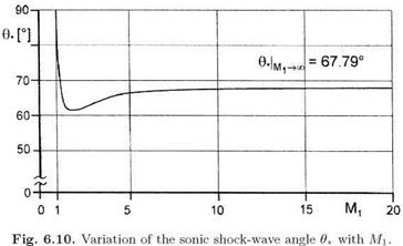
For a perfect gas with y = 1.4 they are 9*Ml^^ = ± 67.79°. In a large Mach number range 9* varies only weakly, Fig. 6.10. For 7 = 1.4 the value of 9* drops from 90° at Mi = 1 to a minimum of approximately 61° at Mi « 1.8, and rises then monotonously to the limiting value 9*Ml= 67.79°, see also Figs. 6.12 and 6.13.
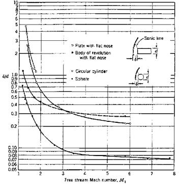
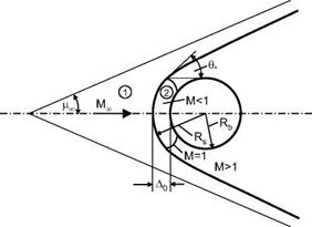
Because for a given Mach number MTO, 90° ^ 9* ^ pTO, Fig. 6.19, the sonic line can meet the bow shock, especially at low Mach numbers, far away from the body surface, Fig. 6.11.
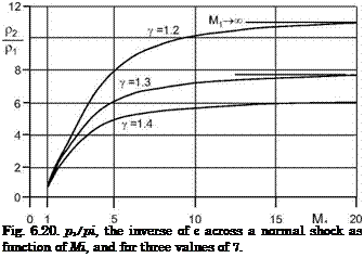
Now to the flow parameters at large upstream Mach numbers, i. e., M1 ^ ж. Generally we obtain the same limiting values across the oblique shock for the ratios of densities, temperatures etc. in the same way as those across the normal shock. We note here only the following exceptions

and finally
|
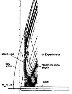
Fig. 6.11. Computed hemisphere-cylinder flow [12]. Mю = 1.05, a = 0°, inviscid flow, Euler solution with shock fitting. The shown characteristics (Mach lines) are those in the symmetry plane.
|
^ ж indeed is larger than that behind the normal shock portion. This holds for all finite Mach numbers Mi > 1, too.
The relations for the velocity components at M1 ^ ж behind the oblique shock are
V2 4y sin2 в
 ——- >■ 1—– — ——
П2 (7 +1)2′
We note finally that the shape of the bow-shock surface, either detached or attached, depends for a perfect-gas flow only on the free-stream Mach number Mi, the ratio of specific heats 7, and the effective body shape with its embedded shock wave and expansion phenomena.[64] All shock relations given above for normal and oblique shocks are valid always locally on bow shock and embedded shock surfaces. If real-gas effects, in particular high-temperature effects, are present, they influence the bow-shock shape, Sub-Section 6.4.1, but also the shock layer, Section 5.4.
Explicit relations, which connect the shock properties to the body shape, are available only for the two-dimensional inviscid ramp flow. These are the oblique-shock relations discussed above.
In Fig. 6.9 we have indicated the angle 5, by which the streamlines are deflected behind the oblique shock. If we select such a streamline, we obtain the two-dimensional ramp flow, Fig. 6.1 d). We find for it the relation between the shock-wave angle в and the deflection angle 5, in terms of the upstream Mach number M1, and the ratio of specific heats 7
|
2 cot 0(M2 sin2 0 — 1)
2 + Mf(7+ 1 — 2 sin2 0)
|
|
|
|
|
|
If the deflection angle 5 is given, the shock-wave angle в can be determined with an iterative scheme. For a quick look-up we give in Figs. 6.12 and 6.13 the shock-wave angle as function of the deflection angle for selected upstream Mach numbers M1 for air with 7 = 1.4 [11].
Eq. (6.114) can be rearranged to yield
|
7 + 1 д f2 sin a sin 0 2 1 cos(6 — 0)’
|
|
|
|
|
|
For small deflection angles 5 it becomes

 01<5 —л0 = A4 = sin
|
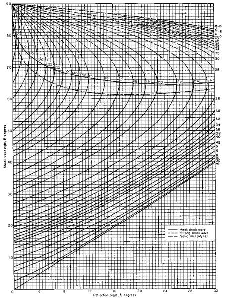
Fig. 6.12. Oblique shock waves: shock-wave angle в [°] as function of the flow – deflection angle 5 [°] for selected upstream Mach numbers Mi for perfect gas (air)
(Y = 1.4) [11].
|
|
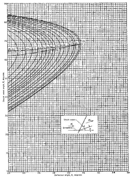
Fig. 6.13. Oblique shock waves (continued): shock-wave angle 0 [°] as function of the flow-deflection angle 5 [°] for selected upstream Mach numbers Mi for perfect gas (air) (y = 1.4) [11].
|
In Figs. 6.1 b) and c) we have noted that at a given free-stream Mach number a critical cone angle exists, at which the bow-shock surface becomes detached (this is called the strong shock wave). Such an angle, 5max, exists also for ramp flow. The (largest possible) shock-wave angle Qsmaxrelated to it—the weak shock-wave limit—is found with
This relation is similar to that for the sonic limit, eq. (6.101). The curves in the respective chart, Figs. 6.12 and 6.13, are similar, too.
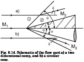
Cone flow, of course, is different from ramp flow, because it has, in a sense, three-dimensional aspects [7]. For a given upstream Mach number Mi and equal values of ramp angle 6 and (circular) cone half-angle a we find a larger shock-wave angle в for the ramp flow, Fig. 6.14.
The flow behind the attached oblique ramp shock is uniform and parallel to the ramp surface. The flow behind the attached shock surface of the cone at zero angle of attack of the cone is also circular, see, e. g., [4, 11]. It is first, i. e., directly behind the shock surface, deflected according to eq. (6.114). The streamlines then approach asymptotically the direction of the cone surface, i. e., the semi-vertex angle a. All flow quantities are constant on each concentric conical surface, which lies between the shock surface and the body surface. The Mach number on the body surface, and hence also away from it, can be subsonic or supersonic, depending on the pairing Mand a. Graphs of the flow parameters for circular cone flow can be found in [11].
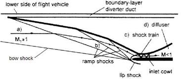
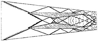
In closing this sub-section we have a look at shock intersections and reflections. Such phenomena can occur, see Chapter 9, in flows past ramps, at
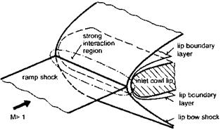
the interaction of embedded shocks and the bow shock but also in flows in propulsion inlets etc., Section 6.1.
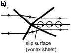
Intersections of shock waves belonging to opposite families in uniform and parallel flow are symmetric, if the incoming shocks are symmetric, i. e., of equal strength, Fig. 6.15 a), and asymmetric, if not, Fig. 6.15 b).[65] In the symmetric case the streamlines are first deflected towards the shock waves. Behind the intersected shocks they are again parallel and uniform. Indeed, this is the governing condition for the shock intersection.
This also holds for the asymmetric case. However, because the involved shocks are of different strength, we get behind the intersection two parallel and uniform streams with different total-pressure loss. Since the static pressures are the same, these two streams have different speeds. The result is, in terms of inviscid flow, a slip surface, which in reality is a vortex sheet, Fig. 6.15b). This vortex sheet can become unstable via the Kelvin-Helmholtz mechanism [13, 14].
 a)
a)
Fig. 6.15. Schematic of intersections of shocks belonging to opposite families : a) symmetric intersection, b) asymmetric intersection.
Shock reflection at a wall can be interpreted, in inviscid flow, as, for instance, one half of a symmetric shock intersection (the upper half of Fig. 6.15 a)). In viscous flow the interaction with the boundary layer must be taken into account. If the effective shock strength is small, a thickening of the boundary layer will happen, otherwise boundary-layer separation will occur, Section 9.1.
We note finally that intersecting shocks of the same family in a triple point T form a single stronger shock [4]. In T also a slip line and an expansion fan originate, see Fig. 9.6 c) in Sub-Section 9.2.1.
![]()




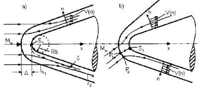
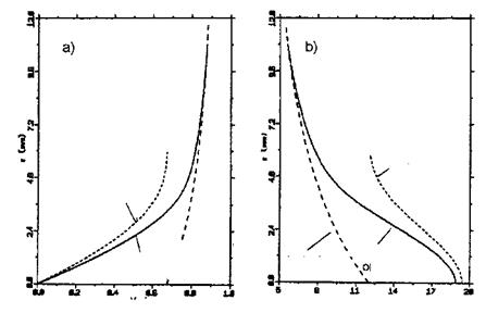 It is clear that we can make a similar consideration assuming constant M^ and constant nose radius Rs, and a changing unit Reynolds number Re Then we observe entropy-layer swallowing with decreasing Re^, because this increases the boundary-layer thickness.


 01<5 —л0 = A4 = sin


 a)
a)