Category Canonical impulse solutions

Compressible infinite swept wing

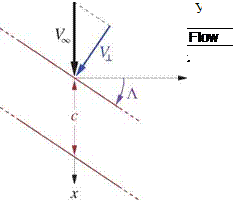
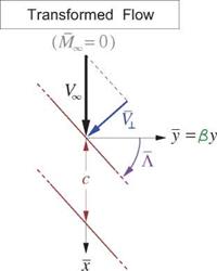
For the compressible infinite swept wing, the PG transformation gives the following modified geometry,

also sketched in Figure 8.17.

a = в a

(8.99)

or equivalently

Л 1

tan A = — tan A

в

-г в cosЛ

(8.100)

/ /і2 cos2A + sin2A

Figure 8.17: Prandtl-Glauert transformation of infinite swept wing.

Applying the previously-derived incompressible solution (8.97) we have

Подпись: (8.101)Cl = Cta a cos Л

Compressible infinite swept wing Подпись: (8.102) (8.103)

and the compressible Cl is then obtained using Gothert’s Rule and the reverse PG transformations.

dCL

да

~ Р ’

Л

х0° (2D)

dCL

cea cos Л

Л –

>90°

да

sin Л ’

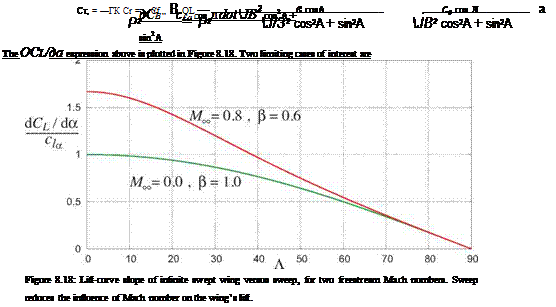
so that large sweep angles mitigate compressibility effects, as can be seen by the coalescence of the incom­pressible and compressible curves in Figure 8.18.

Low-speed infinite swept wing

We will now investigate the lift characteristics of an infinite swept wing. The incompressible case will be considered first, followed by the compressible case treated via the PG transformation in the next section.

Low-speed infinite swept wing Подпись: ■X Low-speed infinite swept wing Low-speed infinite swept wing

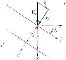
An infinite wing with sweep angle Л and streamwise chord c is shown in Figure 8.16. The angle of attack а is defined along the x-axis as usual, and hence it also appears in the streamwise section.

Figure 8.16: Lift of infinite swept wing is determined entirely by geometry and velocity in perpen­dicular x’z’-plane section.

‘ dv’

<* w +

Low-speed infinite swept wing Подпись: dp dy' Подпись: 0 Подпись: (8.89)

Consider the flow as described in the rotated x’, y’, z’ coordinates where y’ is along the wing, and the x’z’- plane is perpendicular to the wing. Since each y’ location is the same, we must have d()/dy’ = 0 for all flow-field quantities. The inviscid y’-momentum equation is then

which implies that v’ is everywhere constant, and equal to the wing-parallel freestream component

v'(r) = VL єіпЛ = V (8.90)

so as to match the freestream. The continuity and remaining x’, z’-momentum equations are

d pu

‘ d pw’

= 0

dxf

dz’

‘ du’

‘ du’

dp

(8.91)

PUM

+ a?

dx’

dw’

‘ dw’

dp

PUd:¥

~d^

which describe potential 2D flow in the perpendicular x’z’-plane. Specifically, the velocities and pressure fields have the form u’, w’,p'(x’,z’), and depend only on the projected airfoil shape, chord, freestream veloc­ity, and angle of attack, all denoted by the ()l subscript.

= c cos Л

(8.92)

Vl

= VL cosЛ

(8.93)

= а/ cosЛ

(8.94)

And since the pressure field depends only on these parameters, the lift must also, with the spanwise V velocity being irrelevant.

Assuming a± is defined from the airfoil’s zero-lift line, the incompressible 2D-section lift is

dL = pV? c*aa±dS (8.95)

where в£а ~ 2n is the 2D lift-curve slope, and dS = c± dy’ = c dy is an element of wing area on which the element of lift dL acts. The total lift is then

Подпись: L = dL= pV? cta a±_ S

= ^p(Ko cosA)2 C£a (a/cos A) S (8.96)

Подпись: LПодпись: CL =Подпись: 12PVJS дСь да = c£a a cosA (8.97)

= c£a cosA (8.98)

Low-speed infinite swept wing

so that sweep reduces the lift by the factor cos Л relative to an unswept wing at the same a.

Compressible 3D finite wing

Consider a simple, flat rectangular wing with aspect ratio AR and an uncambered airfoil. The objective is to determine its Cl and CD for a given angle of attack a and freestream Mach. Following the PG solution procedure we transform this to x, y,C space where the corresponding transformed wing has

AR = в AR (8.83)

a = в a (8.84)

Compressible 3D finite wing Подпись: (8.85) (8.86)

and its flow-field is governed by the Laplace equation for ф. For a high aspect ratio wing this is approx­imately solved by classical lifting line theory given in Appendix E. The final results for the lift coeffi­cient (E.37) and induced drag coefficient (E.23) can then be directly applied to the transformed problem,

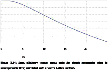
where cfa ~ 2n is the wing airfoil’s 2D lift-curve slope. An offset to a from the wing airfoil camber has been omitted from (8.85), so that a is in effect measured from the transformed wing airfoil’s zero-lift line. The span efficiency e(2R) depends on the transformed wing’s aspect ratio, as shown in Figure 8.14.

Подпись: 0 5 10 -15 20 25 Figure 8.14: Span efficiency versus aspect ratio for simple rectangular wing in incompressible flow, calculated with a Vortex-Lattice method. 1

0.98 0.96

e

Подпись: a Подпись: (8.87) (8.88)

0.94 0.92 0.9 0.88

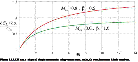
Подпись: Figure 8.15: Lift-curve slope of simple rectangular wing versus aspect ratio, for two freestream Mach numbers.

The 3D lift-curve slope of the wing dCL/да is now seen to depend on в as well as AR, as plotted in Figure 8.18. Two limiting cases or interest are

For a given Cl, the C^ is seen to be mostly unaffected by compressibility, except via the small effect of the span efficiency e which decreases slightly with AR. For a near-elliptical planform we would have e ~ 1,
in which case CD would be essentially independent of ML. This insensitivity of CD to the aircraft flight Mach is consistent with Trefftz-plane theory, in which the lift and the induced drag are implicitly related to each other via the aircraft’s trailing vorticity distribution. The aircraft’s compressible near-field has no bearing on this lift and induced drag relation.

Prandtl-Glauert equation solution procedure

The great practical importance of the PG transformation is that it allows small-disturbance subsonic com­pressible flow problems which are not transonic (not too close to = 1) to be solved by incompressible potential flow methods. This is accomplished by the following systematic procedure.

1. The real flow problem has geometry defined in x, y, z, with given > 0

2. Scale all y, z dimensions by the PG factor (3 = J 1 — . This gives a transformed geometry in the

PG space X, y, a, with a, nx, AR… all reduced by the same factor of в.

3. Calculate the flow over the transformed geometry using an incompressible flow method and related flow models. These include thin airfoil theory, vortex-lattice, panel, far-field approximations, images, etc. This gives the transformed perturbation potential ф(х, у,г), and/or the transformed perturbation velocities фх, фу, фг, pressures Cp, forces Cl, etc.

4. Calculate the physical perturbation potential and/or velocities using the reverse PG transformations.

Подпись: ф(8.71)

Подпись: Фх фУ Фг д(Ф/02)

dx

Подпись: (8.72)д{ф/02)

д(у/Р)

д(Ф/02)

d(z/(3)

With the velocities available, the physical pressure coefficient can now be calculated directly from its exact definition (8.12) . But since the small-disturbance approximation is assumed to be valid here, it’s useful to consider an alternative simplified small-disturbance form based on the asymptotic pressure expression (8.43).

The advantage here is that if the incompressible solution method directly reports the pressures Cp, forces Cl, etc., then the corresponding physical quantities can be obtained immediately. Relations (8.74) and (8.75) are collectively known as Gothert’s Rule [58].

5. To calculate the induced drag coefficient the Trefftz plane wake integral (5.47) can be used, since this only requires that the Trefftz plane’s perturbation flow be incompressible.

|V-V|2/аІ = |Уф|2M£ « 1

Prandtl-Glauert equation solution procedure Prandtl-Glauert equation solution procedure

This is certainly valid even if itself is not small. Applying the reverse PG transformation to the Trefftz plane wake integral gives the required induced drag transformation rule.

Compressible 2D airfoil

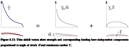
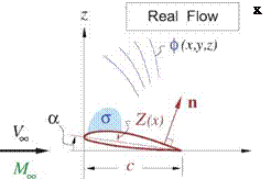
Consider the 2D airfoil problem for compressible flow, shown in Figure 8.12. Assuming the airfoil is very thin for simplicity, its geometry is defined entirely by its Z(x) camberline shape. As discussed in the previous unsteady-flow Chapter 7, and sketched in Figure 8.13, the vortex sheet strength representing the transformed incompressible flow will have the form

5(x) = Ya а + Yz є (8.77)

where ya(x) and Yz(x) are sheet strength distributions for a unit а and a unit camber shape Z(х)/є, respec­tively, with є being the maximum camber value. These unit distributions can be computed a priori. For example, first-order thin airfoil theory as derived in Appendix D gives

7 aO = 2C — — 1

x

and Yz(x) depends in a more complicated manner on the particular unit camber shape. The circulation and lift coefficient will then also have two corresponding independent components.
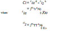
Подпись: Ci = cia a + ciZ Є where cia = f 2?r d№) 0 Кю ciz = f 2TT d№) 0 К» (8.78)

(8.79)

Подпись: Figure 8.13: Thin airfoil vortex sheet strength and corresponding loading have independent components proportional to angle of attack a and maximum camber C.

(8.80)

Prandtl-Glauert equation solution procedure Prandtl-Glauert equation solution procedure Подпись: 1 J2 Подпись: [ cia (ва) + ciz (вє) ] Подпись: 1 P Подпись: [ Cia а + Ciz Є ] Подпись: (8.81) (8.82)

The compressible ci is computed by applying the reverse transformations to the solution (8.78).

The final relation (8.82), called Prandtl’s Rule, states that the 2D lift coefficient for the compressible case increases by the factor of 1/в over the incompressible value (ci)inc for that same airfoil. This can be considered a “shortcut method” for 2D cases, since (ci)inc is the incompressible value for the physical (not transformed) airfoil shape and angle of attack. It also applies to calculation of Cp, cm, etc. However, Prandtl’s Rule does not hold for 3D cases, where it is necessary to perform the PG geometry transformation and then use Gothert’s Rule to obtain the correct compressible solution.

Prandtl-Glauert Analysis

8.6.1 Prandtl-Glauert interpretation

The significance of the Ml term in the PG equation (8.60) can be explained as follows. Starting with the velocity V written in terms of the perturbation potential (8.54) we have

IV (V2) • V

Ко (Фхх + фуу + Фхх) = V • V = а = ————————————– 2——- (8.62)

2 а

where the last term is the field source a as given by the compressible continuity equation (8.1). For small – disturbance flows where |V0| ^ 1 we can now make the following approximations to the quantities above.

Подпись: a Prandtl-Glauert Analysis Подпись: = Ml (VK фхх)

V(V2) — 2V2 (фхх x + фху y + фхх z)

Equation (8.62) then simplifies to

Подпись: (8.63)фхх + фуу + фХХ — MK фх

which is equivalent to the PG equation (8.60). Hence, the extra Mlфхх term in the PG equation is nothing more than an approximation to the field source distribution a(r). The great simplification here is that this ap­proximate field source is now linearly related (i. e. proportional) to the unknown ф(r) perturbation potential’s derivatives, and as a result can be eliminated through a linear variable transformation as follows.

8.6.2 Prandtl-Glauert transformation

The Prandtl-Glauert transformation applies to the overall flow problem, including the boundary conditions. It has a single scaling parameter

f3 = si I-Ml (8.64)

called the Prandtl-Glauert factor (not to be confused with the sideslip angle). The transformation of the flow problem has the form ф(х, у,х;Мто) ^ ф(х, у,х) where the PG variables denoted by the overbar are defined as follows.

{y| = |вУ| , ф = в2ф (8.65)

As sketched in Figure 8.12, the geometry is shrunk in y, z by the в factor. This reduces all the geometric angles, aspect ratios, and also the x components of all normal vectors n = {пх пу nz}T by the same factor.

{

Подпись:Подпись: (8.66)пх

пу

Пх

Подпись: ()x = ()5 ( )xx = ( )з Подпись: ()У = в ()y ()z = P()z ()yy = в ()УУ ()zz = ft2 ()УУ Подпись: (8.67)

It also gives the following relations between the various derivatives.

Prandtl-Glauert Analysis

Using the above transformation relations converts the PG equation and wall BC in physical space into the Laplace equation and wall BC in the transformed space.

фхх + фуу + фгг

= 0

(8.68)

Wall BC: фуПу + фупг or: фу

= – Пх

= Z(х) — cr

(in 2D)

(8.69)

(8.70)

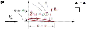
Figure 8.12: Prandtl-Glauert transformation from physical variables (left) to PG variables (right).

The fact that a compressible flow looks incompressible after the PG transformation can be explained or interpreted in a number of ways. One explanation is that the perturbation velocity field in the transformed space has zero divergence and zero curl,

а = V ■ (Vф) = 0 (equation (8.68))

uj = V x(Vф) = 0 (identity)

and hence is an incompressible and irrotational flow. Another useful although less rigorous explanation is associated with the thickening effect, which reduces percentage-wise streamtube area variations in the real flow. A low speed flow over a more slender body also has smaller streamtube area variations, so the y, z – scaled incompressible flow mimics the real compressible flow’s more uniform streamtube area distributions.

. Ranges of validity

Figure 8.11 diagrams the range of validity of the five potential equations considered here, versus |V0|aVg which is a measure of “non-slenderness,” and versus the freestream Mach number MTO.

The following observations can be made:

• At low speeds where ^ 1, all five equations are equally valid, even for non-slender bodies (viscous effects are not being considered here). The simplest Laplace equation is then the logical choice to use here.

• For low-subsonic Mach numbers, above MTO > 0.3 or so, compressibility effects become progres­sively more pronounced, in which case the PG equation becomes the logical choice to use.

• For flows sufficiently close to sonic, MTO ~ 1, specifically transonic flows, the PG equation becomes unsuitable because it cannot represent normal shock waves. In this case the simplest possible equation which can be used is TSD, since it can capture normal shock waves and their associated wave drag.

• For supersonic flows sufficiently far past MTO = 1, the PG equation again becomes valid. In this situation it becomes a form of the wave equation, and can represent weak oblique shocks for which the flow remains everywhere locally supersonic.

• For all but very low freestream Mach numbers, the PG or TSD equations become increasingly re­stricted to smaller body thicknesses and/or small angles of attack as MTO increases. The reason is that the leading terms which were dropped in the PG and TSD derivations were of the form M^фхфу, etc. Hence, for a fixed error from these terms, the upper limit on the tolerable | Vф|avg must decrease as MTO increases. [7]
equations for adequate accuracy. Solving PP2 is not any easier or less expensive than solving the FP equation, so PP2 is not used in practice (here it was only a stepping stone to TSD and PG).

• For all but low-speed flows, FP also has an upper limit on body slenderness, even though no small – disturbance approximations were used in its derivation. The reason is that high-speed non-slender flows will have strong shock waves and large shock-wake velocity defects, which invalidate the isen- tropy and irrotationality assumptions underlying the FP equation.

Perturbation potential flows

We now assume irrotational flow. This allows eliminating the three u, v, w perturbation velocity components in terms of the single normalized perturbation potential variable ф, which is the usual perturbation potential p normalized with the freestream.

ф

= P/V2

(8.52)

u X + v y + w z

= Vф

(8.53)

V = Vo + V2(u x + v y + w z)

= V2 [(1 + фх) X + фу y + фz z]

(8.54)

Note that ф has units of length, so that Vф is dimensionless.

Second-order perturbation potential equation

Подпись: [(i—M2 )Фх Perturbation potential flows Подпись: 0 (8.55) (8.56)

Replacing u, v, w with фх, фу, фх in equations (8.49),(8.51) gives the Second-Order Perturbation Potential (PP2) equation and associated flow-tangency condition:

Transonic small-disturbance equation

We now note that for a small-disturbance flow, most of the quadratic terms in (8.55) can be dropped, except when the freestream flow is close to sonic, ~ 1. In this case we can approximate Q ~ y+1 , and we also note that Qфф. ~ (y + 1) фХ may not be small compared to (1 — ) фх. Furthermore, for slender bodies

we have

Пх ^ Пу j nz

Perturbation potential flows Perturbation potential flows

so that the product фхпх in (8.56) is a higher-order quantity compared to фуny and фznz. Hence we drop all quadratic terms except for фХ, which results in the following nonlinear transonic small-disturbance (TSD) equation, and a first-order flow-tangency condition.

which looks like a Laplace equation except for the фх-dependent coefficient multiplying the фхх term.

Strictly speaking, the quadratic terms ф^ + ф2 in (8.56) should also have been retained in the TSD equa­tion (8.57). However, because of the strong lateral dilation effect shown in Figure 8.5 they are typically much smaller than QфХ and hence can be dropped. One possible exception is in cases with strongly swept shock waves, in which these may need to be retained.

Prandtl-Glauert equation

Подпись: (1 — m2 ) фхх + фуу + фzz = 0 Подпись: (8.60)

Provided the freestream flow is sufficiently far from sonic, we can in addition drop the quadratic term from the TSD equation (8.57) or (8.59) to give the Prandtl-Glauert (PG) equation.

The first-order flow-tangency condition (8.58) remains the same here. The most significant change from the TSD equation is that the PG equation is now linear, which is an enormous simplification which will be extensively exploited in the subsequent sections.

Laplace equation

As a final step, if we assume low speed flow, with M^ ^ 1, the PG equation (8.60) simplifies to the Laplace equation.

фхх + фуу + фzz = 0 (8.61)

Although this equation appears to be subject to the same small-disturbance approximations as its PG, TSD, and PP2 predecessors, it is in fact completely general for any low-speed flow. The reason is that all the higher-order terms which were dropped were also multiplied by M^ or higher powers, so that with M^ ~ 0 all these dropped terms were already negligible anyway. Alternatively, the Laplace equation could also have been obtained directly from the starting continuity equation (8.47) by a priori assuming that p is constant in the low speed case.

Second-order approximations

Using the Taylor series expansion in a small parameter є

(1-е)-1 = 1 + є + є2 + … (8.39)

the local Mach number expression (8.35) is converted from a rational form to a polynomial form,

M2 = MI 1 + (1 + ^M2 ) [2u+u2+v2 +w2] + V./2( 1 + ^M2 ) 4г/2 + … і (8.40)

where “…” denotes cubic terms O[М’Ж|u, v, w|3 ) and higher. Using the more general Taylor series ex­pansion

(1-е)6 = 1 – be + b(b-l)e2 + … (8.41)

Подпись: _p_ p ж p_ Рж Second-order approximations Подпись: (8.42) (8.43)

the isentropic density and pressure (8.36), (8.37) likewise convert from power-law forms to the following polynomial forms.

Again, the “…” denotes cubic terms and higher.

To put the continuity equation into a polynomial form, we first need to expand the components of the normalized mass flux pV/рж Уж. These are obtained by multiplying the р/рж expression (8.42) in turn
with each component of V/V2, and then collecting the various powers and products of u, v,w.

Подпись: — (1+U) = { 1 - Ml u + f.' l>'.l'2)ir + {v2+w2) po

Подпись: — w = 1 1 — M P2 < = w — M2 uw + ... CO 1 Second-order approximations

+ … (1+u)

Second-order approximations Подпись: (8.47) (8.48) (8.49) (8.50) (8.51)

We next insert these mass flux component expressions into the compressible continuity equation, and also put the flow-tangency boundary condition in perturbation-velocity form.

Small-Disturbance Compressible Flows

The full potential equation is very general, but it requires grid-based CFD solution methods which offer little insight into compressible flow behavior. For this reason we will now consider the more restricted class of Small-Disturbance Flows, which in many circumstances can be treated by superposition-based solution methods.

8.5.1 Perturbation velocities

The perturbation velocity is defined in the usual way, as the difference between the local velocity V and the freestream velocity V,. To minimize equation complexity, we will from now on assume that the freestream is along the x axis, so that the angles of attack or sideslip are in the geometry definition. Furthermore, u, v, w will here denote the perturbation velocity components, which are also assumed to be normalized by the freestream speed V,. The local total velocity V and its magnitude V are then expressed as follows.

Подпись:V, = V, X

V = V, [(1 + u)X + vy + wz] V2 = V ■ V = V,2 [ 1 + 2u + u2+v2+w2 ]

– ?r(V2-V*) = cd{l – (7-l)M2[u + i(u2+t;W)]} (8.34)

Small-Disturbance Compressible Flows Подпись: -i Подпись: (8.35) (8.36) (8.37)

The local adiabatic speed of sound, the local Mach number, and the isentropic density and pressure expres­sions can also be expressed in terms of the perturbation velocities as follows.

8.5.2 Small-disturbance approximation

The above restatement of the various flow quantities in terms of perturbation velocities has so far been exact, with no new approximations introduced. We now consider Small-Disturbance Flows, where the condition

u, v,w ^ 1 (8.38)

is assumed to hold. This is generally valid if

• The geometry is slender: t/c ^ 1 for an airfoil, or d/£ ^ 1 for a fuselage.

• The aerodynamic angles are small: a ^ 1 and в ^ 1

Under normal circumstances it is tempting to drop all higher powers of the perturbation velocities like u2,uv, etc. and retain only the linear terms to greatly simplify the flow equations. However, this will be seen to be premature for transonic flows, where some of the nonlinear terms always remain crucial. Hence we will perform the simplification in three steps:

1. First only the cubic and higher terms will be dropped.

2. Next, all the quadratic terms be dropped except the ones which remain indispensable.

3. Next, all the quadratic terms will be dropped, finally giving a linear problem.

Limitations of full potential solutions

One limitation of the FP equation is that it applies only to inviscid flows. This can be mostly remedied by using the Wall-Transpiration boundary layer model described in Chapter 3. For example, in the 2D case the flow-tangency BC (8.24) would be modified to

d m

pV Ф-П = — (8.28)

ds

where m = peue5* is the viscous mass defect. This is governed by a suitable form of the boundary layer equations which would need to be solved together with the FP equation.

Another limitation of the FP equation is that its resulting velocity field V = УФ is irrotational, and hence its solution will not have a shock wake like the one shown in Figure 8.8, even if the solution has a shock present on the airfoil. The wave drag as calculated by far-field integral (8.19) over the shock wake will then incor­rectly be zero. The correct calculation of wave drag therefore appears to require the direct pressure force integration over the airfoil surface via (5.5). However, this was shown to be very sensitive to cancellation errors in Section 5.1.2, so the following more accurate approach is needed.

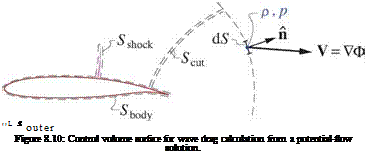
Consider the control volume surface shown in Figure 8.10, consisting of the four pieces Souter, Scut, St>ody, Sshock. The integral momentum theorem in the freestream X direction summed over all four pieces can be assumed to be zero, since the overall contour is topologically empty and contains only smooth potential flow which satisfies the momentum equation.

[ pn + p(V ■ n)V ] ■ X dS = 0 or [ ] dS + [ ] dS + [ ] dS + [ ] dS = 0

outer cut body shock

In addition, in 2D flow the Souter piece can also assumed to be zero since the outer flow is potential and has no momentum defect, and the Scut piece is also zero since its two П vectors are opposite. Hence the two remaining pieces must be equal and opposite, so we have

DWave = [ ] dS

body

= – [ pn + p(V■ n)V ] ■ X dS (8.29)

shock

and therefore the wave drag can be computed by evaluating integral (8.29) only on the contour surrounding the shock, noting that n points into this contour. This avoids the cancellation errors which would occur with evaluating the Sbody integral directly.

Similar arguments can be made for wave drag in 3D potential flows. In this case the Souter integral is only the induced drag Di, which can be evaluated by Trefftz-plane integration over the wake cut as discussed previously. The Sbody integral is then Di + Dwave, so that the integral over the shock-enclosing contour isolates the wave drag component.

Dwave = – S [ pn + p(V■ n)V ] ■ X dS (8.30)

shock

Limitations of full potential solutions

Limitations of full potential solutions