Our heavyweight helicopter equal in the world does not have
In Rostov started production of the most load-lifting rotary-wing car The Russian holding «Helicopt[...]

Everything about aircrafts and helicopters. News and events in aviation worldwide. Civil, transportation, military helicopters and airplanes.

Everything about aircrafts and helicopters. News and events in aviation worldwide. Civil, transportation, military helicopters and airplanes.

Everything about aircrafts and helicopters. News and events in aviation worldwide. Civil, transportation, military helicopters and airplanes.

Everything about aircrafts and helicopters. News and events in aviation worldwide. Civil, transportation, military helicopters and airplanes.


Inherently unstable/augmented aircraft systems are often highly augmented leading to very high-order dynamic systems (HODS) [47]. Mathematical description of aircraft and flight control system includes rigid and elastic body dynamics, actuator model, sensor models, and flight-control filters, and this would result in models of very high order. By LOTF approximation one can express the characteristics of an aircraft-control system in terms of flight mechanics models to appropriately evaluate the HQs. For this model, order reduction techniques for generation of equivalent LOTF are required. Generation of LOTF for analytical evaluation of HQs is a very important part of the overall FCS development process for a modern high – performance aircraft. The direct methods for evaluating HQs are piloted flight simulation and flight testing. The HQ criteria are often specified in terms of second-order TF constants with some additional parameters, such as time delay. Generation of LOTF with a specified structure and order becomes important for highly augmented aircraft. Because of increased control system integration, sophistication, and coupling, it becomes difficult to compute LOTF as additional modes are introduced in the region of pilot crossover.
There are several methods for obtaining LOTF models for HQ evaluation: (1) frequency response matching (amplitude and phase) over a selected range using numerical search routines, (2) system identification methods based on I/O data collected from flight tests and piloted simulation, and (3) balanced model reduction technique based on model decomposition of HOTF models in to high-, mid-, and low-bands and Hankel reduction of each of the three subsystems [6-8].
In the case of the frequency response matching technique, the cost normally used is
1 N
J = – V(AG/ + WDp2)
j=1
Here, N = number of discrete frequencies w,; AG is the amplitude difference, in decibels, between the actual (HOTF data) and (LOTF) model predicted response; AP is the phase difference in degrees; and W is the weighting factor, usually chosen as 0.018. The frequency range should be chosen to include the essential modes of the aircraft, the usual choice being 0.1-10 rad/s. For the frequency range, 20 points per
|
E-1 (Equation system bounds) E-1 (Equation system bounds)
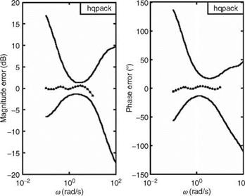
FIGURE 10.8 LOTF estimation error bounds for a configuration. (From Shaik, I., Evaluation of NLR handling qualities database for a large transport aircraft using HQPACK. Project Document FC 0519, National Aerospace Laboratories, Bangalore, December 2005. With permission.) |
decade can be used for model fitting. The structure of the LOTF model should be akin to the aircraft modes to be evaluated for HQ. Figure 10.8 shows error bounds obtained for fitting an LOTF to an HODS of a transport aircraft.
Due to augmentation of roll control, some low-frequency oscillations in roll could be possible. This could be mainly due to coupled roll-spiral modes and control surface rate saturation. too high or too low roll response could lead to lateral PIO tendencies.
TABLE 10.13
Pilot-Induced Oscillation Conditions for Bandwidth Criteria Condition Remarks
 Theta BW >1 and phase delay <0.14 s Theta BW >1, phase delay <0.14, and pitch rate overshoot (in frequency domain) >9 dB Theta BW <1 and pitch overshoot >12 dB If phase delay >0.14
If phase delay >0.14 and flight path BW <0.55 rad/s If phase delay >0.2
10.7.2.1 Ralph-Smith
Ralph-Smith criterion can be used for prediction of roll attitude PIO [33]. If the phase of the roll angle to roll control force TF (at the crossover frequency) is less than —180°, then the aircraft is prone to roll PIO.
10.7.2.2 Phase Rate
Phase rate criterion is used as a guide in control-law design [46]. The requirement is the same as for the APhR for the longitudinal PIO.
This criterion is based on phase margin [36,37]. The theta loop should have sufficient phase margin to avoid PIO sensitivity. The pilot model is not required. The flight is PIO sensitive if the phase angle of F j) TF (at the open loop gain crossover frequency) is less than —165°. It is PIO prone if the angle is less than —180°. Also, for the normal acceleration TF, if fm = 180 + f(j«c) — 14.3 «c < 0, then the flight is PIO prone.
10.7.1.2 Phase Rate Criterion
Excessive phase lags are encountered in modern high-performance aircraft. APhR (average phase rate) is the pitch attitude phase per unit frequency; the range of frequency is up to 2«180. This would capture the HO effects. APhR is computed as
![]() — (180 + f 2v180 )
— (180 + f 2v180 )
«180
10.7.1.3 Loop Separation Parameter
During landing, the flight path and theta loops could be treated as independent of each other, since during the flare the pilot would concentrate rather on flight path control [40]. This means that pilot models could be different for each loop and also the dominant resonance frequencies. If loop separation parameter (LSP) = pilot-aircraft closed loop system resonance frequency (of pitch attitude minus of flight path) is less than 2 rad/s, then the aircraft is prone to PIO. Appropriate pilot models are required.
10.7.1.4 Neal-Smith Time-Domain Criterion
The criterion uses the pilot compensation model defined as [14,41-43]
de(s) _ 400Kp(rleads + 1)e-0 23s Ue(s) s2 + 28s + 400
This model includes the second-order lag filter and an equivalent time delay of 300 ms. The pitch attitude control task is monitored for 5 s. The theta-errror (of the closed loop control) rms value is minimized. The rms value of the second derivative of the theta-error is computed. If this is greater than 100, the prediction is that the aircraft is PIO prone.
10.7.1.5 Bandwidth PIO Criterion
Bandwidth PIO criterion is specified in terms of the PIO rating boundaries in terms of BW and phase delay of the theta TF [34,44,45]. UBC also uses the flight path BW and the time-domain theta dropback. The parameters are obtained from the Bode diagrams of theta, pitch rate, and the flight path. Also, step response of the pitch attitude is used. The unified BW PIO criterion boundaries are defined. Table 10.13 specifies the PIO conditions.
10.7.1.1 Ralph-Smith Criterion
The longitudinal PIOs are classified in three types [32-35]: Type IPIO is expected to occur when the pilot ‘‘switches’’ control tracking pitch attitude to tracking of the pilot-felt normal acceleration. Type II PIO is expected to occur as a result of an abrupt turbulence or nontracking abrupt maneuver. Type III PIO tendency is caused by the pitch attitude tracking only. The main idea is that the aggressive tracking behavior (of pilot-aircraft) should not result in pilot-aircraft closed loop instability. The conditions for the Ralph-Smith (RS) criterion (Types I and II) are
Here, f (j«R) is the phase angle of the normal acceleration TF and 14.3 vR
is the phase lag as a result of pilot delay of 0.25 s. The condition for Type III PIO is that the phase angle of pitch attitude TF (with respect to force input at the crossover frequency) would be less than —180°. «R is the resonance frequency of the power spectral density (PSD) of the normal acceleration due to the closed loop control of pitch angle. In the case of the Type II PIO the resonance frequency is from the PSD of the pilot-aircraft open loop system. The pilot model for normal acceleration is simple gain with a pure time delay of 0.25 s, and for the theta loop it is a lead/lag model with a 0.3 s time delay, the time constants of which are ‘‘adjusted’’ according to the crossover pilot model. The RS criterion requires an explicit pilot model.
Pilot-induced oscillations (PIOs) are oscillations of the PAS occurring inadvertently. For high-performance aircraft with fully powered control systems, PIOs could occur rather frequently [5]. The pilot can be regarded as an adaptive controller (of the vehicle) whose capabilities exceed those of the most sophisticated unmanned control systems. The performance of the pilot and the system can be predicted under certain circumstances. The man-machine system is thus amenable to mathematical analysis. This is also because the system adjustments adopted by the pilot for uncoupled multiloop feedback systems are consistent with those of good feedback systems. For more complicated multiloop systems, the pilot model and analysis methods have a continuing practical usefulness. The mathematical models used in PAS analysis could be TF type. The inputs and outputs of the nonlinear elements (friction, breakout, nonlinear gearing) of interest in PIO can be approximated by a pair of sine waves. Before a PIO, the pilot adopts a quasistationary set of feedbacks and equalizations (phase lead/lag, gains) that amount to the performance of a good control system (stability, small error). After a PIO the airframe motion changes to a nearly sinusoidal motion. For pre-PIO adaptation, the simplified rule is |Yo| = |YpYc| ffi |y| in the vicinity of the crossover frequency 1-2 rad/s [5]. In the case of the actual PIO phase, the terminal phase of pilot adaptation is synchronous or precognitive behavior. The pilot essentially duplicates the sinusoidal with no phase lag and Yp ffi Kp. However, in most PIO cases the pilot has adapted the pre-PIO strategies. Before PIO the pilot uses visual and motion cues to perform the basic flying task. When the PIO limit cycle occurs, the dominant input is the acceleration felt by the pilot. The pilot outputs are the forces and displacements applied to the control stick/pedals. The pilot then has both force and displacement control loops within his or her neuromuscular actuator system.
While adapting to a flight operation/phase, some factors cause a sudden change in the situation dynamics [5]: (1) change in the pilot’s organization/adjustment of the system, (2) initiation of a large steady maneuver, or (3) a damper failure. Subsequently, the oscillations build up and are sustained for a few cycles—a limit cycle exists. Soon the pilot realizes or feels this and starts controlling, and pumps in the stick commands.
Unmanned aerial vehicles (UAVs) are finding increasing applications in military and other civilian operations, and the study of their dynamics is gaining importance in recent times. For remotely piloted vehicles several aspects are important: remote interaction of the test pilot with the vehicle, ground station interaction/software, flight displays, and data link time delays. UAVs are used for conducting specialized and complex missions. For the remote test pilot of the UAV the ‘‘seat-of-the pants’’ cues are not available. Data link/transmission time delays can have adverse effects
|
Condition |
v180 |
vBWp |
vBWg |
vBW |
TP |
Task A |
Task B |
Task D |
|
|
Pitch axis |
Hover |
6.298 |
2.8 |
4.12 |
2.8 |
0.078 |
1 |
1 |
1 |
|
Roll axis |
Hover |
12.27 |
8.09 |
4.87 |
4.87 |
0.042 |
1 |
1 |
1 |
|
Yaw axis |
Hover |
2.235 |
0.246 |
1.39 |
0.246 |
0.074 |
3 |
— |
— |
|
Pitch axis |
Forward flight |
5.862 |
2.56 |
3.49 |
2.56 |
0.081 |
1 |
1 |
1 |
|
Roll axis |
Forward flight |
12.06 |
5.47 |
6.56 |
5.47 |
0.048 |
1 |
1 |
1 |
|
Yaw axis |
Forward flight |
6.39 |
3.27 |
5.09 |
3.27 |
0.015 |
2 |
— |
— |
|
TABLE 10.11 Bandwidth Criteria Evaluation for BO 105 Helicopter |
|
HQ Levels |
|
Source: Shaik, I., Wolfgang, V. G., and Hamers, M. HAT—A handling qualities analysis toolbox. NAL Project document FC 0210, November 2002 (also as IB 111-2002/27, DLR). Note: Task A—target acquisition and tracking; Task B—all mission task elements, UCE = 1, and fully attended; Task D—all mission task elements, UCE > 1 or divided attention. |
on the system’s HQ. Small UAVs exhibit higher natural frequencies than large aircraft. Therefore, even if these UAVs are rated (by test pilots) to have good HQs they would fall outside the conventionally specified HQ boundaries for short period. A dynamic scaling method can be used [31] to adjust the military standard for short – period mode. One can use the dynamic (Froude) scaling to provide common ratios between inertia-to-gravity and aerodynamic-to-gravity forces for vehicles with different geometrical dimensions (large – to small-scale vehicles). The following relation is handy, with N as the scaling factor:
Table 10.12 shows a comparison of a few parameters of Cessna-182 aircraft and StablEyes UAV. StablEyes (BYU Captsone 2004) has a span of 0.61 m, mean aerodynamic chord (MAC) of 0.15 m, cruise velocity of 15 m/s, and an average wing sweep of 8°.
|
TABLE 10.12 Comparison of a Few Parameters of a Light Aircraft and an Unmanned Aerial Vehicle
Source: Foster, T. M. and Bowman, W. J. Dynamic stability and handling qualities of small unmanned-aerial-vehicles. 43rd AIAA Aerospace Sciences Meeting and Exhibit. Reno, NV, 10-13 January, 2005. |
Despite the differences in the size and dimension of these two aircraft, there is a good similarity between the nondimensional derivatives. Cessna-182 has an HQ Level 1. However, the UAV has an HQ Level 2. As rated by the pilot the UAV has good HQ rating. When the scaling of N = 80 was used, and the HQ boundaries were adjusted, the UAV fell within the adjusted HQ Level 1 [31].
Height response (HR) criterion: The HR criterion of heave axis response (HAR) is to evaluate the rotorcraft’s dynamic behavior following a step collective input in hover. While applying the collective input the pitch, roll, and heading excursions should be maintained essentially constant. According to ADS-33, the vertical rate response should have a quantitative first-order appearance for at least 5 s. The first-order TF can be fitted to this 5 s response:
h _ Ke-Ts d ~ 1 ± Ts,
where T is the equivalent time constant and t is the equivalent vertical axis time delay.
This criterion can also be evaluated in the frequency domain. For HQ Level 1 the max T is 5 s and max delay is 0.2 s, and for HQ Level 2 the max T is infinity and the delay is 0.3 s.
Torque response (TR) criterion: The torque displayed to the pilot is used as a measure of the maximum allowable power that can be commanded without exceeding the engine or transmission limits.
Some case study results of BW criterion for BO 105 helicopter data are given in Table 10.11.
Bandwidth criterion: The BW criterion of yaw axis response (YAR) is similar to the PAR BW criterion; however, the minimum limits imposed are higher than those for the pitch axis.
Dynamic stability criterion: Here, more relaxed limits are placed on the damping ratio than pitch – and roll-axis oscillations. For Level 1, the minimum value of 0.19 is specified for yaw damping ratio for all oscillations with a frequency of more than 0.5 rad/s.
Attitude quickness criterion: The parameters are the heading quickness and the minimum heading change Dcmin required.
Large amplitude criterion: The large amplitude heading changes is for yaw control power in terms of the maximum achievable yaw rate: the limit for moderate agility MTE is ±22°/s for Level 1 HQ.
Bandwidth criterion: The BW criterion of roll axis response (RAR) is similar to the pitch axis response (PAR) BW criterion.
Dynamic stability criterion: The dynamic stability criterion addresses the oscillatory roll modes following a lateral doublet in hover. These oscillations are dominated by DR mode. The limits on the natural frequency and damping of these oscillations are similar to the pitch axis limits.
Altitude quickness criterion: The altitude quickness criterion is for the bank angle changes of moderate amplitude between 10° and 60°.
Large amplitude criterion: This measures the absolute control power in terms of the maximum achievable roll rate (for a rate-command system). It measures the maximum achievable roll altitude change for an altitude command system. A typical limit for moderate agility MTE is ±50°/s for Level 1 HQ.
TABLE 10.10
Possible Handling Qualities Criteria Matrix for Helicopters
HLSR Forward Flight Requirements
 Direct Axis/Inter-Axis Coupling (Response Criteria) Direct Axis/Inter-Axis Coupling
|
Pitch |
Roll |
Yaw |
Heave Yaw due Pitch due |
Roll due |
Pitch |
Roll |
Yaw |
Heave |
Pitch due Pitch due |
Roll due |
|
to roll to roll |
to pitch |
to roll to roll |
to pitch |
|||||||
|
BW |
BW |
BW |
HR AA AA |
AA |
BW |
BW |
BW |
Flight path |
||
|
control |
||||||||||
|
DySt |
DySt |
DySt |
TR |
DySt |
DySt |
DySt |
||||
|
AQ |
AQ |
AQ |
Pitch control |
AQ |
||||||
|
power |
||||||||||
|
LA |
LA |
LA |
LA |
LA |
||||||
|
SpSt |
||||||||||
|
BW = |
Bandwidth |
criteria; |
Dyst = Dynamic stability criteria; |
AQ = Attitude |
quickness |
criteria; LA |
= Large-amplitude criteria; HR — Height response |
criteria; |
|
AA = Aggressive agility; and SpSt — Spiral stability. |
The handling qualities analysis tool is an integrated MATLAB/GUI-based SW for analytical evaluation of the HQs of aircraft and rotorcraft [27]. The HQ criteria for military helicopters specified in ADS-33 and the HQ and pilot-induced oscillation (PIO) prediction criteria specified for fixed-wing aircraft in MIL-STD-1797A are covered in this toolbox. The input information could be in the form of time histories, state-space models, TF, or frequency response data. It is important that an adequate theoretical/analytical evaluation of HQ is carried out at the design and development stage of an airplane, before thorough evaluation in flight. For this purpose mathematical models are used and experimental evaluations can be made on flight simulators. Table 10.10 gives a brief overview of certain possible HQ criteria to be evaluated for a helicopter. A brief description of some of the tabulated criteria is given next.
10.5.3.1 Hover and Low-Speed Requirements (HLSR)—Pitch Axis Response Criteria
Bandwidth (BW) criterion: It addresses the small amplitude and short-term pitch attitude changes to control inputs. vBW and phase delay tp are determined from the frequency response of the pitch attitude to longitudinal cyclic frequency sweep input. For rate command vBW should be lesser than wBWs and wBw For attitude command
vBW = wBw,. Phase delay criterion: tp = 5<723(2°v^l. v180 is the frequency at which the phase angle is —180°, vBW is the frequency at which the gain margin is 6 dB, and vBW is the frequency at which the phase margin is 45°. These quantities are computed for the given test conditions and are placed on the pitch BW HQ level templates to determine the criteria that meet the levels of HQ.
Dynamic stability (DySt) criterion: These are the natural frequency and damping ratio of the oscillatory mode especially of phugoid and Dutch roll. In hover, these modes are coupled. These parameters are determined from the responses and compared against the pitch axis dynamic stability HQ level boundaries.
Attitude quickness (AQ) criterion: Attitude quickness criterion measures the agility of the rotorcraft. The metrics are дЦ8// and the minimum attitude change.
These parameters are compared on the ADS-33 HQ level boundaries for the target acquisition and tracking task.
Large amplitude (LA) criterion: ADS-33 specifies minimum achievable angular or attitude change; for example, for moderate agility mission test element, Level 1 limit is ± 13°/s and +20/—30° altitude.