Our heavyweight helicopter equal in the world does not have
In Rostov started production of the most load-lifting rotary-wing car The Russian holding «Helicopt[...]

Everything about aircrafts and helicopters. News and events in aviation worldwide. Civil, transportation, military helicopters and airplanes.

Everything about aircrafts and helicopters. News and events in aviation worldwide. Civil, transportation, military helicopters and airplanes.

Everything about aircrafts and helicopters. News and events in aviation worldwide. Civil, transportation, military helicopters and airplanes.

Everything about aircrafts and helicopters. News and events in aviation worldwide. Civil, transportation, military helicopters and airplanes.


Boeing/Sikorsky RAH-66 Comanche military helicopters are designed to meet the HQ specifications of ADS-33D [29]. ADS-33D (aeronautical design standards)
|
TABLE 10.9 Comparison of Handling Qualities Evaluation Results for a Large Transport Aircraft (E5)
Source: Shaik, I. Evaluation of NLR handling qualities database for a large transport aircraft using HQPACK. Project Document FC 0519, National Aerospace Laboratories, Bangalore, December 2005. |
 |
|
sp
 |
FIGURE 10.5 CAP criterion evaluation for E5. (From Shaik, I., Evaluation of NLR handling qualities database for a large transport aircraft using HQPACK. Project Document FC 0519, National Aerospace Laboratories, Bangalore, December 2005. With permission.)
|
Large supersonic aircraft criterion (FC E-5)
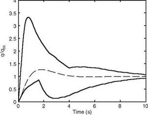
FIGURE 10.7 Pitch rate time-history criterion evaluation for E5. (From Shaik, I., Evaluation of NLR handling qualities database for a large transport aircraft using HQPACK. Project Document FC 0519, National Aerospace Laboratories, Bangalore, December 2005. With permission.) |
contains the requirements for the flying and ground HQs for rotorcraft [30]. These requirements should be complied with, by the process of analysis, simulation, and flight tests at various stages of the design and development of a helicopter. Some of these are the following: (1) Prior to the critical design review—analytical checks should be computed/made using the available math models; (2) Prior to the first flight—analytical checks should be made using full nonlinear math models, which include the feel system and SCAS elements. Also, the assessment should be done in flight simulators by the test pilots; (3) After the first flight, except for maneuvers that are hazardous or impractical, the flight test verification of all maneuvers should be carried out. ADS-33D defines the flying qualities in terms of Levels 1, 2, and 3 as well as UCE (usable cue environment) of 1, 2, and 3. UCE depends on the assessment of the displays and vision aids that are provided to the pilot. The UCE level is determined from VCR (visual cue rating) scale for at least three pilots. The ADS-33D requirements are specified in terms of small-, medium-, and large- amplitude changes. In essence, the ADS-33D HQ assessment relies upon objective analysis.
The HQ criteria are also evaluated by the pilot in a fixed-base or motion-based simulators or finally in an actual airplane by performing a flight operation/maneuvers as specified by the design engineer/analyst. The HQ evaluation pilot should have several qualities [1]: (1) motivation, (2) communication skills, (3) confidence in his or her own capability and courage to give a frank opinion of the performance, and
(4) objectivity, and (5) piloting experience. A minimum of three pilots are required for such exercises. It must be added that the pilot’s opinion (rating) and evaluation also form part of this exercise. The HQ criteria for fixed-wing aircraft applicable to fighter aircraft are detailed in Ref. [8].
10.5.1 HQ for Large Transport Aircraft
The large transport aircraft (LTA) here is under Class III. It is important to comprehensively study and evaluate the HQ of this class of aircraft. HQ criteria based on the dynamic characteristics of the aircraft only are [1,28] (1) LOTF of the aircraft, (2) open loop time response/pitch rate response criterion, (3) steady manipulator forces in maneuvering flight, (4) dynamic manipulator forces in maneuvering flight,
(5) compatibility of steady manipulator forces and pitch acceleration sensitivity,
(6) C* time-history envelope, (7) large supersonic aircraft criterion, (8) shuttle pitch rate time-history envelope, (9) dropback criterion, and (10) rise time and settling time criterion.
HQ criteria based on PAS are (1) pilot-aircraft closed loop dynamic performance, (2) pilot-aircraft ‘‘inferred’’ closed loop dynamic performance, and (3) modified
Neal-Smith criterion. HQ large transport aircraft software (HQLTASW) [28] is evaluated with the NLR’s database for Fokker F28/Mk6000 aircraft. This aircraft is a medium weight, twin-engined jet transport aircraft. The rate-command/altitude hold control system was selected for pitch and roll control. Longitudinal HQ evaluation for a transport aircraft is primarily important because the main purpose of a transport aircraft is takeoff, cruise, and landing. LOTF were used for the HQ evaluation studies. NLR evaluated HQ of this aircraft using the ground-based and IFS experiments, as well as various analytical criteria. A typical configuration, E5 [1], has a complete pitch rate TF:
q(s) 19.20 + 0.0831)0 + 0.706)0 + 0.870)
qCO) _ (s + 0.0775)0 + 0.838)0 + 10)(s2 + 2(0.699)(1.2)s + 1.44)
Some overall results of HQ evaluation using HQLTASW and compared with NLR’s predictions are shown in Table 10.9 (with entries as the HQ levels) for this configuration.
The HQ levels specified by the CAP criterion vs. short-period damping ratio for the configuration E5 (and also other configurations studied in Ref. [1]) are depicted in Figure 10.5 [28]. The chosen configuration E5 meets the Level 1 HQ. The HQ level requirements of short-period frequency and load factor (with respect to alpha) are depicted in Figure 10.6. The E5 configuration meets the Level 1 specification as can be seen from the figure. The pitch rate history in normalized form should lie within boundaries specified in Figure 10.7. The configuration E5 falls within the specified boundaries. It might be necessary to modify certain criteria (like BW/N-S) for their applicability to LTA.
Assessments are done in terms of normalized roll rate and bank angle oscillations for a step roll command input [23-26]. The roll rate oscillations should be kept to an absolute minimum. The requirements are based on the linear model of the aircraft. The roll rate and bank angle oscillation boundaries are defined. The roll rate at the first
|
TABLE 10.6 LD Modes Specified Values |
Flight Phase Category |
Level 1 |
Level 2 |
Level 3 |
|
Time to double the roll angle should be |
A, C |
12 |
8 |
4 |
|
greater than |
B |
20 |
8 |
4 |
|
Zrsvrs |
B, C |
0.5 |
0.3 |
0.15 |
|
Equivalent roll time delay should be less than |
— |
0.1 |
0.2 |
0.3 |
|
Source: Shaik, I. and Chetty, S. HQPACK User’s Guide, Vols. 1, 2. PC based SW package in MATLAB ver 5.2 for the prediction of handling qualities and pilot induced oscillation tendencies of aircaft. NAL Project document, PD-FC-9810, December 1998. |
|
TABLE 10.7 DR Mode Parameters Specified Values
Source: Shaik, I. and Chetty, S. HQPACK User’s Guide, Vols. 1, 2. PC based SW package in MATLAB ver 5.2 for the prediction of handling qualities and pilot induced oscillation tendencies of aircaft. NAL Project document, PD-FC-9810, December 1998. |
minimum, following a step input, after the first peak should have the same polarity. It should not be less than the specified percentage of the roll rate of the first peak: For Level 1 Categories A and C 60%, for Category B 25%; and for Level 2 Categories A and C 5%, for Category B 0%. For bank angle HQ level boundaries are specified in Ref. [8].
10.4.2.3 Roll Performance
Roll performance is indicated by the time to achieve the specified roll angle change [6,8]. Certain requirements for various classes of aircraft are often specified (Table 10.8).
|
TABLE 10.8 Time to Attain the Specified Change in Roll Angle for Classes I and II Aircraft Category A Category B Category C
Source: Shaik, I. and Chetty, S. HQPACK User’s Guide, Vols. 1, 2. PC based SW package in MATLAB ver 5.2 for the prediction of handling qualities and pilot induced oscillation tendencies of aircaft. NAL Project document, PD-FC-9810, December 1998. |
The pilot should be able to make certain necessary maneuvers and changes in the roll altitude. As far as possible the sideslip should be zero.
10.4.2.4 Sideslip Excursions
While making a turn, coordination between yawing and banking is required so that the aircraft does not ‘‘skid.’’ The pilot should be able to make precise changes in the heading. There should be minimum yaw coupling in roll entries/exits, and the sideslip excursions should be minimal. The pilot usually performs a coordinated turn. The required yaw control for coordination of turn entries and recoveries should not be objectionable to the pilot. The limits on the amount of the sideslip permitted after a small step roll command (up to the magnitude that causes a 60° roll angle within 2 s) are specified. The maximum sideslip excursions (during coordination in turn entry/exit) permitted are 6° for Level 1/Category A; 10° for Level 1/Categories B and C; and 15° for Level 2/all categories, for right roll command (this causes adverse beta). For left roll command (which produces the right sideslip/pro verse) the limits are 2° for Level 1/ Category A; 3° for Level 1/Categories B and C; and 4° for Level 2/all categories [6,8].
Unit step and pulse responses and the turbulence response of the aircraft are studied as is done in the case of the longitudinal mode. The idea is that these responses should be acceptable from the control point of view and the RMS value of the turbulence should be acceptable.
The ratio is computed at the Dutch roll (DR) frequency. This modal characteristic helps in deciding the damping factor (damping ratio and frequency product). It signifies the relative roll oscillations with respect to the sideslip excursions. The latter aspect is of high significance in turn coordination.
10.4.2.2 LD Modes
Various LD modes are evaluated. These are discussed here.
Roll mode: The requirements are specified in Table 10.5. A good correlation is found between roll mode time constant and pilot rating.
Spiral stability: The time to double the roll angle should not be less than the specified values (see Table 10.6) following a disturbance of up to 20° in roll angle. This would reduce the workload of the pilot.
|
TABLE 10.5 Handling Qualities Specified Values for Max Roll Time Constant
Source: Shaik, I. and Chetty, S. HQPACK User’s Guide, Vols. 1, 2. PC based SW package in MATLAB ver 5.2 for the prediction of handling qualities and pilot induced oscillation tendencies of aircaft. NAL Project document, PD-FC-9810, December 1998. |
Coupled bank-spiral oscillations: The aircraft should not have a coupled bank – spiral mode for flight phase of Category A. It should not have coupled bank-spiral oscillation for Category C. For Categories B and C, the roll-spiral damping coefficient Zrs vrs should not be greater than the specified values. The idea is that the roll control effectiveness should not be sacrificed. Also, the combined time delay due to various components in the aircraft-control loop should be limited so that the pilot’s tracking is not degraded (Table 10.6).
Dynamic LD response parameters: The minimum required values are specified in Table 10.7. The damping limits the DR oscillations.
Due to the importance of the flight at HAOA, lateral-directional (LD) criteria are also used [8].
10.4.2.1 Lower-Order Equivalent TF
LOTFs are computed as follows [21,22]:
f(s) Ke—TS ; Ke—TS ;
8a(s) s(s + 1fTRy 8r(s) s2 + 2Zd(Bds + w2d ’
f(s) _ LSa(s2 + 2£фШфs + vf)e—;
8a(s) (s ± 1fTs)(s + 1fTr)(s2 + 2Zd(Bds + (B2d) ’
b(s) Nda(s + 1/Tp1)(s + 1/Tp2)(s + 1/Tb3)e—Ts
8r(s) (s ± 1fTs)(s + 1fTr)(s2 + 2ZdBds + uj)
The values of the gains and time delay could be different for each TF. Poles and zeros of the open loop TF are computed. The roll angle and sideslip TF could be fitted independently to the given HODS frequency responses. From the LOTF model several modal characteristics are computed and are dealt with in the description of other criteria [6,8].
|
TABLE 10.3 Handling Qualities Specified Values for Transient Response Parameters
Source: Shaik, I. and Chetty, S. HQPACKUser’s Guide, Vols. 1, 2. PC based SW package in MATLAB ver 5.2 for the prediction of handling qualities and pilot induced oscillation tendencies of aircaft. NAL Project document, PD-FC-9810, December 1998. |
combination of both types of responses. The criterion is used by control system designers. The C* boundaries are specified for various categories of the flight phases. C* is given as
C*(t) = normal acceleration in g’s + 12.4 q(rad/s)
The value of 12.4 is arrived at as crossover velocity (121 m/s) divided by “g.”
10.4.1.4 Gibson’s Criteria
Gibson’s criteria are based on both time and frequency responses of the aircraft [19,20]. The pitch attitude after following the stick command remains constant when the input is removed. The attitude dropback is defined as the condition in which the attitude goes back to its previous value after the stick input is removed. These criteria are applicable to linear systems and mainly to maneuvering type of aircraft, as the criteria do not consider flight path control. Since the criteria are generally used for flight control development and optimization, the HQ level boundaries are not
|
TABLE 10.4 Handling Qualities Specified Values for Rise Time Terminal Flight Phase Nonterminal Flight Phase
Source: Shaik, I. and Chetty, S. HQPACK User’s Guide, Vols. 1, 2. PC based SW package in MATLAB ver 5.2 for the prediction of handling qualities and pilot induced oscillation tendencies of aircaft. NAL Project document, PD-FC-9810, December 1998. Note: All the rise time entries should be divided by the true velocity (in ft/s). |
really defined. The pitch attitude dropback should not be negative for Categories A and C flight phases. For Category A the frequency response specifications are = 0.55; <Bymax = 1.95. For approach and landing some boundaries are speci-
nfa nja
fied. The frequency at —120° phase (lag) is required to be within 0.25 and 0.5 Hz. The pitch attitude frequency response should have gained attenuation greater than 0.1°fdB at —180° phase. The phase rate should be lower than 100°fHz. Many other aspects of Gibson’s criteria are discussed in Refs. [16,17].
Closed loop criterion uses an additional cascade TF with the pilot’s model [15]: .
This term signifies integration at low frequency. The two forms used are given as
No HQ boundaries are given. The additional term is necessitated due to the use of 3DOF equations for computation. It might be necessary for the pilot to perform this integration to avoid the droop at frequencies lower than the BW frequency. The closed droop should not be more than —3 dB for Levels 1 and 2. The closed loop resonance should not be greater than 3 dB for Level 1, and 9 dB for Level 2 (over the range 0-10 rad/s).
10.4.1.3 Pitch Rate Response
The aircraft-control system’s state responses to a unit step can be obtained [16]. In addition, its response to turbulence can be obtained and RMS values can be computed. All the four longitudinal states are plotted. From the pitch rate response, several time-domain specifications can be studied. These specifications are standards from the conventional control system requirements: rise time, transient peak ratio, etc. The pitch rate peak ratio is computed as
(max value — steady-state value)/(steady-state value — min value)
The peak ratio signifies the damping of the system. A tangent line (extending from the steady-state horizontal line to the time axis) is drawn at the point of maximum slope. The effective time delay is computed as
time of the intersection of the tangent at maximum slope with the steady-state line — time of the intersection of the tangent with the time axis
The limits are given in Tables 10.3 and 10.4. The criteria are applicable to conventional and many pitch augmentation systems.
The HQs of an airplane, in a closed loop, can also be determined from its stability margins [12]. The bandwidth (BW) is taken as the lesser of the gain (6 dB) and phase (45°) margins’ frequencies. A phase delay parameter characterizes the phase roll off, and it is very similar to the equivalent time delay parameter. The phase delay is defined as
T v180_______________
ph ~ 57.3 x 2w180
v180 is the frequency at which the phase is —180°, f2vi80 is the phase at twice the v180 frequency. These parameters are computed from the Bode diagram of the pitch attitude TF. The phase delay vs. BW HQ level bounds are specified. The BW is also an important control design criterion. Higher BW would be preferable, but it might cause increased ‘‘dropback.’’ The unified BW criterion (UBC) considers the flight path dynamics and it is useful for the landing task [13]. It considers pitch attitude BW, phase delay, flight path BW, pitch attitude dropback, and the pitch rate overshoot. HQ level boundaries are defined for these parameters. The UBC also checks for the dropback.
10.4.1.2 Neal-Smith Criterion
 |
Neal-Smith criterion is used for assessment in terms of the pilot workload [14]. The aircraft is flown in closed loop as shown in Figure 10.4. The first block is the pilot model. It is assumed that the pilot performs the closed loop pitch attitude control
task, and hence the pilot’s compensation is a measure of the pilot’s workload. The HQ level boundaries are specified in terms of the closed loop response (resonance) amplitude and the pilot’s compensation. The pilot model parameters are tuned to obtain minimum closed loop resonance. The droop allowed is up to —3 dB. The lead/lag compensation used by the pilot (determined from the pilot’s control – theoretic model) is used in the HQ level boundaries. The point of this criterion is that it evaluates the closed loop performance.
The idea behind CAP is that the initial pitch attitude response of the aircraft is useful in ascertaining the ultimate response of the flight path [10,11]. The initial pitch acceleration is sensed by the pilot. The load factor parameter being related to the flight path curve is useful in defining this criterion.
CAP1: This criterion is defined as
u0 2 v2P
—— (rad/s /g); an approximation of this is given as (for LOTF)—.
Anzs n/a
Here, the numerator is the initial pitch acceleration and the denominator is the steady-state change in the load factor.
CAP2: This criterion is defined as UmaxHODS (rad/s2/g), based on the maximum pitch acceleration.
|
TABLE 10.1 Handling Qualities Specified Minimum Values
Source: Shaik, I. and Chetty, S. HQPACK User’s Guide, Vols. 1, 2. PC based SW package in MATLAB ver 5.2 for the prediction of handling qualities and pilot induced oscillation tendencies of aircaft. NAL Project document, PD-FC-9810, December 1998. |
CAP3: This criterion is defined as based on the quasisteady-state pitch rate.
nzs
—2 –
CAP4: This criterion is defined as qmaxHODS based on the peak value of the
pitch acceleration for step command from the pilot. CAP4 is approximately equal to the CAP1 approximation. The CAP values where applicable are computed from the parameters of the LOTF or the HODS.
The CAP and the equivalent short-period damping Zsp should be within the HQ level bounds. Table 10.1 gives the minimum values for the Category C flight phase.
The product — spTU represents the phase lag at —sp. It is also an equivalent time delay between the pitch attitude response and the flight path response. If the two responses are adequately separated then the pilot gets a proper cue for controlling the outer slow path. This nondimensional equivalent parameter should fall within the specified HQ bounds. Other limits are the following: For Category A flight phase! Level 1, —sp > 1.0, and for Level 2, —sp > 0.6. For Category C, Table 10.2 gives the HQ specified requirements.
|
TABLE 10.2 Handling Qualities Specified Minimum Values for Time Constant
Source: Shaik, I. and Chetty, S. HQPACK User’s Guide, Vols. 1, 2. PC based SW package in MATLAB ver 5.2 for the prediction of handling qualities and pilot induced oscillation tendencies of aircaft. NAL Project document, PD-FC-9810, December 1998. |
The time delay тв max limits are specified as the following: For Level 1 as 0.1 s, for Level 2 as 0.2 s, and for Level 3 as 0.25 s. The equivalent time constant is important in attitude dynamics as well as for the flight path. Additionally, the short-period frequency and the acceleration parameters are also evaluated. It is interesting to note here that the CAP1 approximation is related to the static margin. The vsp, boundaries for categories of flights and the levels are also specified in MIL-F-8785C.
The pitch acceleration, an important flight mechanics parameter, is related to pitch control derivative as
At high angle of attack a high value of the nose up pitch acceleration is encountered and adequate control recovery power is required to overcome this pitch acceleration.
Evaluation of aircraft’s longitudinal HQ is very important [8]. This is more so for any fighter aircraft than a transport aircraft. Next we discuss several such important criteria.
10.4.1.1 Lower-Order Equivalent TF
An adequate lower-order equivalent TF (LOTF) is required to assess the longitudinal HQs of an aircraft for short-period performance, and this is done in terms of the equivalent parameters [1,9]: Zsp, vsp, 1/T0, тв. This is because the aircraft with feedback controllers (filters with gains and time constants) and other subsystem dynamics becomes a very higher-order dynamics system (HODS). Thus, it would be very convenient to reduce this HO aircraft-control dynamic system to an equivalent lower-order system and judge the adequacy of the parameters mentioned here in terms of evaluation specifications. The HQ evaluation then becomes easy in a manner similar to that for conventional aircraft, more so if the responses are of the conventional type. If the responses are not of the same type as the conventional aircraft, then this approach is not preferable. LOTFs are obtained in the following forms:
Ф) _ Ku(s + 1/T)e~TeS ^ nz(s) _
SeO) S2 + 2ZspVspS + V2p Se(s) S2 + 2Zsp VspS + v2p
The frequency range for fitting LOTF to HODS is taken as 0.1-10 rad/s. The procedure for obtaining the LOTF is explained in Section 10.10. The parameters of LOTF are better used in conjunction with another criterion known as control anticipation parameter (CAP) discussed next.