Category Fundamentals of Modern Unsteady Aerodynamics

Weissinger’s L-Method

Weissinger’s L-Method
The Prandtl’s lifting line theory is not valid for the wings which have forward of backward sweep of more than 15°. For highly swept wings the method proposed by Weissenger is widely used. Weissenger’s method, rather than ignoring the terms with (x — П), it replaces by half chord, b, to simplify Eq. 4.11a. This approximation is justified physically because it considers the average value of term (x — П) rather than neglecting it. Rewriting Eq. 4.11a with this simplification we obtain

This alteration saves the second term on the right hand side of 4.28 being from singular. Now, we define the Weissenger’s L function

In this form Eq. 4.29 is valid for the wings with their quarter chord line parallel

to y axis

image66

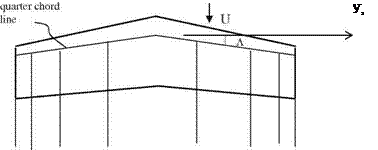
When the wing has a sweep, Weissinger places the bound vortex at the quarter chord line and applies the boundary conditions at the three quarter chord line. The bound vortex is placed at both sides of the wing with the sweep angle Л as shown in figure below where the wake vortices are also indicated as straight lines parallel to main stream

Let us now write down the Weissenger’s L(y, g ) function with sweep

Подпись:Подпись: (4.30)11 1 dG dg* l* dG

Подпись: L(y*, g*) Weissinger’s L-Method

The L function in 4.30 is more complex compared to the one in 4.29, (BAH 1996). For y > 0 ve g > 0 the function becomes

(4.31)

When sweep angle Л goes to zero, Eq. 4.31 becomes 4.29. If we transform the spanwise coordinates, as we did for the case of lifting line theory with y* = cosu and g* = cosh and expand the circulation term into Fourier sin series, the nec­essary aerodynamic coefficients are obtained through solution of 4.30 (BAH 1996).

Lifting Line Theory

Lifting Line Theory Lifting Line Theory

The Prandtl’s Lifting Line Theory is valid only for the high aspect ratio wings. For high aspect ratio wings, x — П value can be neglected compared to – — " in first term of the right hand side of Eq. 4.11b. While making this assumption here, we presume that as x approaches П and – approaches ", the vortex sheet strength is not too large. Now, if we use the fact that (- — ")2 is much larger than (x — П)2 we can simplify the double integral in 4.11b as follows

b

Substituting 4.12 into 4.11b we obtain

bi

Подпись:U0£a = 1 f 7a(n^dn – 1 f dr d"

0x 2л x – П 4л d" – -"

-b – i

In Eq. 4.13, if we neglect the second term at the right hand side we obtain the two dimensional steady state flow relation between the vortex sheet strength and the equation for the profile. The second term, on the other hand, is the contribution

Lifting Line Theory Подпись: b + x 9za(x, y) d b — x 8x Подпись: і 1C b dr dg 2 4 dg y — g —і Подпись: (4.14)

of the spanwise circulation change. In order to invert Eq. 4.13 we multiply the equation with J (b + x) /(b — x) and integrate with respect to x we obtain

Подпись: ci Lifting Line Theory Подпись: 1 + Г w(Q 1 — n* и Подпись: (4.15)

In two dimensional steady flow the sectional lift coefficient obtained before was

Lifting Line Theory Подпись: b + x 8 Zg(x, y) dx b — x 8x Lifting Line Theory Lifting Line Theory Подпись: 2 Ubci (y) (4.16)

If we compare the left hand side of 4.14 with the right hand side of 4.15, and consider the spanwise dependence also for any section on the wing we obtain

In small angles of attack the sectional lift coefficient is proportional with the angle of attack. This enables us to define the lift line slope as a(y) = 9c/ 9a. The lift coefficient becomes

ci(y) = 88a(y) = a(y)a(y) ^4.17)

Подпись: r(y) Подпись: Uba(y) Подпись: a(y) Подпись: і 1 dC dg 2a(y)U dg y — g —і Подпись: (4.18)

Using 4.16 and 4.17 in Eq. 4.14 we obtain the formula for Prandtl’s lifting line theory as follows

In Eq. 4.18 the expression given in brackets is a function of y and it is the effective angle of attack. The effective angle of attack is nothing but the difference between the sectional angle of attack a and the angle induced by the downwash which is also induced by the tip vortices of the wing.

An efficient method of solving Eq. 4.18 to find the spanwise circulation is the Glauert’s Fourier series method. Let us first transform the spanwise y and g coordinates from і to — і with

y = і cos / and g = і cos в

Expansion of the circulation distribution into sin series only enables us to have the vanishing circulation values at the tips. Having the Fourier coefficient with no dimension suggests the following form for the circulation expression

Г(ф) = Uaobo^^An sinn/. (4-19)

n=1

Подпись: Г(ф) Подпись: Uab Lifting Line Theory Подпись: (4.20)

In Eq. 4.19 the coefficient aobo denotes the lift line slope and the half chord values at the root. Using 4.19 and its derivative in 4.18 we obtain

Подпись: sin пф P ; sin ф P

The integral tables give that / coc°/ПОСОО o

0 co co

Lifting Line Theory Lifting Line Theory Подпись: bnn sin пф 2l sin ф Подпись: (4.21)

Hence, we obtain

Equation 4.21 is valid for the whole span from left tip to right tip with An being the unknown coefficients once the geometry of the wing is specified. In order to determine these unknown coefficients we have to pick first N terms in the series together with the sufficient number of spanwise stations along the span so that we end up with the number of unknowns being equal to number of equations written for each station. After solving the system of equations for the unknown coeffi­cients, we obtain the circulation value at each station using 4.19. If we examine Eq. 4.19, we observe that for odd values of n, n = 1, 3, 5, … , the circulation values will be symmetric with respect to wing root and for even n, n = 2, 4, 6, ., will be antisymmetric. The integration of the circulation along the span with the Kutta-Joukowski theorem gives the total lift and the lift induced drag. For a symmetric but arbitrary wing loading the total lift and the induced drag coeffi­cients in terms of the aspect ratio AR and the wing area S become

CL = na0lb0lA1/S, (4.22a)

CDi = CL/(nAR)Y^ nA/A. (4.22b)

n=1

Prandtl’s lifting line theory helps us to find the pitching moment distribution along the span of a wing. At a section of a wing, the moment is determined as the summation of the moment acting at the center of pressure (mcp = 0) with the moment at the aerodynamic center (mac) where the moment is independent of angle of attack. Thus, we place the bound vortex at the quarter chord where the lifting force is acting. To find the moment at the quarter chord, the moment at the aerodynamic center is transferred to the quarter chord.

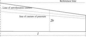
Shown in Fig. 4.2 is the line of centers of pressure and the line of aerodynamic centers for a swept wing which is symmetric with respect to its root. Let us first
find the distance XAC between the aerodynamic center of this wing to the reference line with integrating the sectional characteristics along the span

і

Cl(y)Xacb(y)dy

Xac = —l (4.23a)

Ci(y)b(y)dy

0

Now, the moment with respect to the aerodynamic center can be found with defining Dxac(y) = Xac – xac(y) at each section as follows

і

Mac = j (mac – L Axajdy (4.23b)

0

Here, L0 denotes the sectional lift.

Example 1: A rectangular wing which has an aspect ratio of 7 has a symmetrical profile. Find its lift coefficient in terms of the constant angle of attack a.

Solution: Since the wing is symmetric with respect to its root, we take only the value of odd n. It is sufficient to choose 4 station points with /, = p/8, p/4, 3p/8 and p/2 to find 4 unknown coefficients An, n = 1, 2, 3, 4 with four equations written for each station.

For a being constant at each station Eq. 4.21 gives

Подпись: 14

Подпись: 1Подпись:Подпись: 2AR sin /,

Подпись: Fig. 4.2 Lines of enter of pressure and aerodynamic centers on a wing
image65

a,- = ^2 An sin n/i

n=1

Since the angle of attack is constant the solution of the final equation gives A1 = 0.9517a, A3 = 0.1247a, A5 = 0.0262a, A7 = 0.0047a The lift coefficient for the wing then becomes

Steady Flow

Подпись: and Подпись: 0y Ox 0dw Ox Steady Flow

Under steady flow conditions the terms involving time derivative vanish in Eq. 4.3b and, since the pressure difference at the wake is zero, the spanwise vortex sheet strength at the wake also vanishes, i. e., yw = 0. This results in the continuity of the vortices

Equation 4.7b dictates that dw is only the function of y. At the trailing edge the Kutta condition imposes the following restriction on the chordwise component of the vortex sheet

dw(x, y) = dw(xt, y) = da(xt, y)

which means its value is constant along x at a constant spanwise station. If we integrate Eq. 4.7a with respect to x and differentiate the result with respect to x, the Leibnitz rule gives the following for the chordwise component of the surface vortex sheet strength

Xt Xt

0ya d dx/ dxt

da(xt, y) = Oydx + 0 = dy 7adx + Уа(x/; У)dy _ 7a(x‘; У)"dy

x/ x/

The last two terms of the last expression vanish because of the character of the vortex sheet. Only contribution comes from the first term which is the derivative of the bound circulation to give

dw(y) = da(xt; y) = (4.8)

dy

Equation 4.8 tells us that the wake vorticity has a component only in stream wise direction and its strength varies with the bound circulation. The downwash expression then reads as

Incompressible Flow About Thin Wings

Thin wing theory is an efficient tool for the study of the spanwise variation of aerodynamic characteristics which has effect on the total lift and moment coefficient of a finite wing. This variation is considerably slow except at the tip region of the high aspect ratio wings. For low aspect ratio or delta wings, on the other hand, the aerodynamic characteristics vary rapidly in their short span. Another characteristic of the finite wing theory is the downwash generation because of the tip vortices, which in turn induces drag. The magnitude of the induced drag is proportional with lift and inversely proportional with the aspect ratio. The physical model we use for the three dimensional aerodynamic analysis is based on the two dimensional vortex sheet spread over the wing surface and its wake. In this model, imposing the boundary conditions on the wing the spanwise and the chordwise components of the vortex sheet strength are expressed in terms of the downwash as an integral equation. The remaining task now is the inversion of this integral equation with different assumptions relevant to the flow conditions. Let us now build our model for different wing shapes to find the aerodynamic coefficients.

4.1 Physical Model

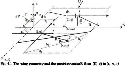
Let the unsteady components of the vortex sheet strength on the wing surface immersed in a free stream with angle of attack be given by y(x, y, t) in spanwise direction and be given by d(x, y, t) in chordwise direction, respectively. In Fig. 4.1, shown are the wing surface in the free stream and the relevant geometry for the point (x, y, z) at which the vortex sheet induces the downwash under consideration.

According to the Biot-Savart law the infinitesimal vortex with intensity of Tds located at a point (П, g) induces a differential velocity dV at a point (x, y, z) as

follows

U. Gulfat, Fundamentals of Modern Unsteady Aerodynamics, 95

DOI: 10.1007/978-3-642-14761-6_4, © Springer-Verlag Berlin Heidelberg 2010

Incompressible Flow About Thin Wings

The relations between the distances and the angles become

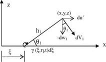
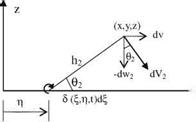
R = (x – П)2+(у – g)2+z2, Й1 = R cos b1, h2 = R cos b2-

Incompressible Flow About Thin Wings
image63

Viewing the x-z plane from у-axis, we can find the differential velocity dVj induced by the spanwise vortex sheet component у as follows

Similarly, looking at y-z plane from x axis, dV2 component induced by y d can be written as

1 S(у – q)d%dq 2 _-4n R

Подпись: *■ yimage64

Подпись: S dq cos в2 4n R2

1 Szd^dq

‘4П R

The induced velocities given above are in differential form of the perturbation velocities. If we want to find the effect of whole x-y plane we have to find the integral effect to obtain the total induced velocity components at a point (x, y, z) as follows

Подпись:,, + 1 Z c(n f)zdndg

(-Гy, z, 0 = — – – – -3=2,

Подпись: w Incompressible Flow About Thin Wings Incompressible Flow About Thin Wings

4p (x – П)2 + (y – g)2 + z2

The components of the induced velocities at the lower and upper surfaces of the thin wing have the following relations for z = 0±

u'(x, y, 0+, t) = – u'(x, y, 0-, t) and v(x, y, 0+, t) = – v(x, y, 0-, t).

Now, we can write the relation between vortex sheet strength components and the perturbation speeds.

c(x, y, t) = u'(x, y, 0+, t)-u'(x, y, 0 , t)=°x – 0/1 and,

d(x У, t) = v(x У, 0+, t)-v(x, У, 0- t) = 0/u – ^y1.

In the last two lines, if we take the derivative of the first equation with respect to y, and the second equation with respect to x, they become equal, i. e.,

Due to the presence of the wing in a free stream, there are three distinct flow regions: (i) the wing surface Ra, (ii) wake region Rw, and (iii) rest of the area in x-y plane.

In addition, we can define the lifting pressure as the pressure difference between the lower and upper surfaces of the wing as follows,

Dp = pi – pu

The Kelvin’s equation can be written for the pressure differences of the wing surface and the wake region

X

“p = o~tj t)dn + UУ; t) (43a)

Xi

Xt X

= Ojt Уа(П; V; t)dn + Ojt У Cwfe V; t)dn + U7w(X; У; t) (4-3b)

X

Incompressible Flow About Thin Wings Подпись: (4.4)

At this stage, we can consider the downwash as the velocity induced separately by the vortex sheet of the surface and the wake region

Подпись: wa(X; У; t) Подпись: 0za 0za ~dt + UaX; (x,y)c Ra Подпись: (4.5)

If the equation of the wing surface is given as z = za(x, y, t), the downwash on the surface becomes,

In the wake region, since there is no lifting pressure the unsteady Kutta con­dition becomes

—Pw(x, y, t) = 0; (x, y) c Rw (4.6)

In the rest of the x-y plane, there is no vortex sheet in our model.

The remaining task here is to find the lifting pressure in terms of the surface vortex sheet strength given as 4.3a. The surface vortex sheet and the wake vortex sheet strengths are related to each other via unsteady Kutta condition, 4.3b and 4.6, This relation is used to eliminate the wake vortex from Eq. 4.4. If we now use 4.5 to express the downwash in terms of the equation of surface, we obtain the integral relation giving the surface vortex sheet strength in terms of motion of the wing. The resulting integral equation contains double integral, and quite naturally it is not analytically invertible! Depending on the geometry of a planform we can make simplifying assumptions to this integral equation and find approximate solutions. It is convenient to start inverting the equation for steady flow.

Gust Problem, Kussner Function

The unsteady aerodynamic response of an airfoil to an arbitrary gust is going to be studied here. An airfoil under the gust load undergoes a motion which consists of arbitrary rotation about any arbitrary point and arbitrary heaving. Therefore, its behavior cannot be modeled with the downwash at the three quarter chord point. The downwash changes with respect to time and position on the airfoil as the gust impinges on. Hence, we need a new independent variable to express the downwash on the surface. This new variable depends on the free stream speed with which the gust moves on the surface of the airfoil. For this reason the downwash at the surface becomes:

Wa(x, t) =Wa(x — Ut).

The gust velocity impinging on the airfoil surface is due to the motion of the air. The downwash on the other hand has an opposite sign to that of gust. If the gust profile is given as wg then the downwash reads as

wa (x — Ut) = — wg(x — Ut).

In Fig. 3.12 the downwash distribution caused by impinging gust on airfoil surface.

As we did before, let us find the response of the airfoil to unit excitation impinging on to the leading edge as a gust at t = 0. If the constant gust speed is wo, time dependent gust function

If the gust is not simple harmonic, we have to consider all the harmonics of the gust and integrate the expressions for the aerodynamic coefficients in the fre­quency domain. The integral representation gives us

1

Ф) = W° J 1{C(k)[J0(k) — iJi(k)] + iJ(k)}eik(s—1) dk

—1

and

Подпись: cm (s)2 Ф).

Now, let us relate the lift coefficient to a new function called the Kussner function as follows

Ф) = 2pUjv(s).

Here, the Kussner function is the indicial admittance for a sharp edged gust.

The Kussner function in terms of the reduced time reads as

1

v(s) = {C(k)[J0(k) — iJi (k)] + iJi(k)}eik(s—1)dk.

pi k

—1

Let us write the coefficient in the curly bracket of the above integral with its real and imaginary parts as Fg(k) + i Gg(k), and write the exponential multiplier with its sin and cosine components, the unilateral integral then reads as a real function of s

v(s) = 2 [F,(k) — Gg(k)]sin(ks)sjnkdk. (3.44)

p k

0

The approximate and convenient form of 3.44 function becomes

v(s) ffi 1 — 0.5e—013s — 0.5e—s. (3.45)

The Kussner function now can be interpreted as the indicial admittance of a sharp edged gust and can be implemented in the Duhamel integral to obtain the responses as the unsteady aerodynamic coefficients expressed in reduced time s,

s

2p,

Ф)= U wg(r)V(s — r)dr] (3.4-ба)

0

and

cm (s)=2 Ф). (3.46b)

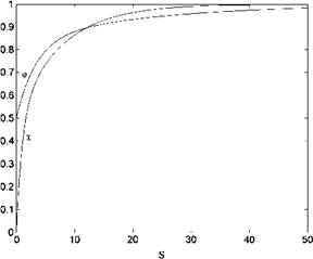
In Fig. 3.11, also shown is the graph of Kussner function which changes more rapidly in time as compared to Wagner function.

There are two other gust problems which are going to be considered here. These are: (i) sinusoidal gust and, (ii) moving gust problems.

(i) Sinusoidal gust, Sears function: Here, the gust acting on the profile is

assumed to change sinusoidially with respect to time and space. The gust intensity with amplitude wo and frequency xg has the functional form

Wg (x, t)=w0ei2KSi (t-U)

Here, k is the wave length of the gust. For the sake of convenience, we choose the form the gust such a way that at the midchord it starts with a zero effect, i. e.,

wg (t) = woelkgt

If we let kg = 2 p U/k to be the frequency of the gust, the lift coefficient in terms of the Theodorsen and Bessel functions

ci(kg, t) = 2pU°fc(k)[Jo(k)- iJ1 (k)] + iJ (k)}elkgt

A new function, the Sears function, can be defined as

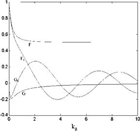
S(kg) = C (kg )[Jo (kg)- 1J1 (kg)] + 1J1 (kg) = F + lGs
whose graph is shown in Fig. 3.13. The corresponding lift coefficient then reads

Подпись: Fig. 3.13 Sears, S = Fs + l Gs and Theodorsen functions, real and imaginary parts
image58

ci (kg; t)=2pUs(kg)eikgt •

(ii) Moving gust problem, Miles functions. Here, we consider the effect of a gust moving with speed of Ug against or in the direction of free stream speed U. The resulting indicial admittance is the Miles function which is given in terms of a ratio

U + Ug

This function has a significance in rotor aerodynamics. There is a sufficient amount of information about this function and its implementations in Leishman. The parameter k takes the value between 0 and 1. When the gust speed is zero k becomes unity and the Miles function becomes Kussner function. On the other hand, for very large gust speeds k approaches zero and Miles function behaves like Wagner function (Fig. 3.11).

We have given, in summary, some analytical expressions involving the Wagner and the Kussner functions. Let us now look at another application for which a ‘time varying free stream problem’ is considered. This problem can be used to model the unsteady aerodynamics for the forward flight of a single helicopter blade.

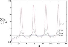
Example 5 A rotating blade in a forward flight is modeled at its section with a sinusoidally varying free stream speed under constant angle of attack. Obtain the unsteady variation of the sectional lift coefficient in terms of the quasi steady lift coefficient and plot its variation by time for different intensities of the changing sinus term.

Подпись: Fig. 3.14 Effect of the time varying free stream on the lift coefficient
image59

Solution: We can write the sinusoidally varying free stream speed at a section with U(t) = Uo (1 + k sin mt). The formulae 3.43-a, b for the arbitrary motion can be used to obtain the sectional coefficient as follows

s

pb • 2p

Ф) = UUa + U[U(s)a0/2 + U(r)aoU0(s – r)dr]

0

For k = 0.2 and k = 0.2,0.4,0.6,0.8 values of the ratios of the unsteady sectional lift coefficient to quasi steady coefficient are plotted with respect to time (Fig. 3.14).

The plots are obtained for four period of free stream starting at zero time. The intensity of the change in the free stream causes peaks at the lift coefficient. In each plot, there is a transition period after the onset of the motion.

As observed from the graphs the difference between the minimum and maxi­mum of these curves increase with increasing k.

Arbitrary Motion

There will be two different arbitrary motions to be studied. First, we will see the unsteady aerodynamic force and moment created by the arbitrary motion of the airfoil. Afterwards, the response of an airfoil to a sharp edged gust will be studied.

3.2 Arbitrary Motion and Wagner Function

Подпись: Fig. 3.10 Change in the amplitude of Loewy function with (h/b) and k
image56

The response of the linear system to a unit step function is defined as the indicial admittance function, A(t), see Appendix 6. The response of the same system to the arbitrary excitation is given by the Duhamel integral as x(t)

t

x(t) = A(0)f (t) + J f (x)A'(f – x)Ax.

0

Подпись: Za(x, t) Подпись: h — ax, and w(x, t) = —A + U—a K J —t —x Подпись: (h + ax + Ua).

Let us find the indicial admittance, A(t), as the unsteady aerodynamic response of the system for the arbitrary motion of the airfoil. As a two degrees of freedom problem let the airfoil pitch about its midchord while undergoing vertical trans­lation. As is given in the previous section the equation for the chordline for a = 0 reads as

This downwash expression w can be used in Eq. 3.32a, b, for a simple harmonic motion with regarding the time derivative of the downwash as the apparent mass terms. This gives

Arbitrary Motion Подпись: (3.35a, b)

ci = arm—U2 || ж*

and the quasi steady terms from 3.31a, 3.31b

2p p

cqs = (h + ckb/2 + Ua) and c^, = (h + Ua).

In Eq. 3.35a, b regarding noncirculatory terms which are the time derivatives of the vertical translation h and the angle of attack a, the coefficients become

2p Pb

Подпись: (3.36a, b)c7 = C(k)(h + ab/2 + U a)+ y(h + Uck)

U U2

p pb

cm = C(k)(h + ab/2 + Ua)— y(ba/4 + Ua)

U 2U2

The first terms of both coefficients given by 3.36a, b depend on the Theodorsen function and they are valid for simple harmonic motions only. The second terms, on the other hand, are independent of the type of motion and they are just time derivatives of the vertical translation and the rotation. If we closely examine the expression in the parenthesis of the first term, (h + ab/2 + Ua), we observe that this is nothing but the expression for the negative of the downwash at the three quarter chord, i. e.,

w(b/2, t) = —(h + ab/2 + Ua).

We have seen in Eq. 3.36a, b that the circulatory terms of the aerodynamic coefficients are the function of the reduced frequency. Here, the downwash at the three quarter chord point is sufficient to find the sectional coefficients. When there is an arbitrary motion, the downwash will change arbitrarily. Since the problem is linear, we can write the Fourier components of the arbitrary downwash and superimpose the contribution of the each component on integral form to the sec­tional coefficients. For this purpose let us define the Fourier integral in the fre­quency domain

w(2; ^ = 2P J f (m)ewxdm (3.37)

— 1

Here, Дю) is the Fourier transform of the downwash and covers its full fre­quency spectrum. The inverse Fourier transform in terms of the downwash value at the three quarter chord becomes

f (x)= J, tje m‘dt (3.38)

—1

The circulatory lift at a given frequency ю can be defined as the Fourier component of the total circulatory lift. This component, on the other hand, can be written for a unit amplitude of the downwash as follows

eixt

Подпись: 2n u

Подпись: Acc[(m, t) Подпись: C(k)eixt.

The corresponding Fourier component for the circulatory lift at time t becomes

This component can be put into the Fourier integral

11

cci(t)=— J Accl(m, t)elx‘dm = —^J f (x)C(k)elx‘dm.

—1 —1

If we employ the same procedure for the moment coefficient, the total coeffi­cients read as

pb 1

c() = U# + Ua)—~U f (m)C(k)emtdrn

—1 і (3.39a, b)

pb 1

cm (t) = —Uji(b’a/4 + Ua)— — f (x) C(k)elxtdx

Equations 3.39a, b are applicable for the arbitrary downwash and covers piecewise continuous functions with finite Fourier transform.

Since the aerodynamic system we consider is linear, the step function repre­sentation of the downwash and the superposition technique will be applied for the aerodynamic effect of the unit change in one of the followings

(a) for a = 0, change in h,

(b) for h= 0, change in a for U = constant,

(c) for h= 0, change in U for a = constant.

Now, let us consider case (b) when U is constant the angle of attack changes from zero to a finite value ao. The downwash becomes

w(f, f) = — aoU1(f). The Fourier transform of this reads as

Подпись: aoU iw f(w) = —aoU J 1(f)e-ixtdf

—1

Substituting this function into the circulatory lift expression we obtain

1

cc,( f) = ao C(k)ei“fdro.

ix

—1

Подпись: cC (s) Arbitrary Motion Arbitrary Motion

If we use the reduced time s = Uf/b instead of f we get

Подпись: u(s) Подпись: 1 2n Arbitrary Motion

From this integral we define a new function

—1

as the Wagner function u(s), the circulatory lift coefficient becomes

cC (s) = 2naoy(s). (3.40)

The Wagner function is a time dependent function whose limit for t going to infinity approaches unity so that according to 3.40 the lift coefficient goes to 2nao-

Let us reduce the Wagner function into a numerically integrable form. If we write the complex exponential with sin and cosine terms, take the Fourier trans­form of the unit step function and consider the symmetry and antisymmetry involved in the integrands, we obtain the Wagner function in terms of the real and imaginary parts of the Theodorsen function as follows

u(s) = 2 ^-^sin (ks)dk = 1 +2 G(k)cos (ks)dk (3-41)

p k p k

0 0

For practical uses an approximate form of the Wagner function is given in BAH as

u(s) ffi 1 – 0.165e_00455s – 0.335e-03s. (3.42)

The graph of the Wagner function, based on the Jones approach and given by 3.42 is plotted in Fig. 3.11. The function at zero time takes the value of 0.5 and reaches unity at infinity. This means, after the sudden angle of attack change it takes a long time to reach the steady state value given by 3.40.

Arbitrary Motion

Knowing the expression for the Wagner function, we can give the unsteady aerodynamic coefficients for the arbitrary motion as functions of the reduced time in the form of Duhamel integrals.

(3.43a, b)

Подпись: Fig. 3.11 Wagner, u and Kussner, v functions
image57

We have previously seen that the Wagner function is 0.5 at t = 0. This means, the immediate lifting response of an airfoil to a sudden angle of attack change is half the lift value attained steadily. These responses are seen explicitly in the circulatory terms of 3.43a, b.

Another example for the arbitrary motion of the profile is the response to a sharp edged gust which will be studied next.

Loewy’s Problem: Returning Wake Problem

The theory of Theodorsen is developed for an airfoil whose wake extends to undisturbed farfield. On the other hand, more complex motions of an airfoil can be studied by the aid of the Theodorsen function. A representative example for that is the study of a helicopter blade or a blade of a propeller. Loewy and Jones sepa­rately studied this problem with the parameters N being the number of blades and h being the distance between the blade and the returning wake. Now, let us give the related formulas for the modified version of the Theodorsen function for a single blade and the multi-blade rotors.

(i) Single blade: The modified Theodorsen function is given in terms of X being the rotational speed of the blade in radians per second and h:

C'(kAh) «T(k>+J.(k>W and

Подпись:V X ‘ Hf>(k> + /H02>(k>+2[/1(k> + i70(k>]W

where W, – = (ekh/be‘2p-/X) _ 1>-

b X

Here, in Eq. 3.34a, b if we let h go to infinity we recover the Theodorsen function as expected. In addition, if the ratio given by XX is an integer, which means the oscillation frequency of the profile is multiples of rotational speed of the blade then the vortices shed are in phase according to 3.34a, b.

(ii) N-blades: For this case W as function is altered with number of blades N and AW as follows

—, – AW, N = ekh/bei2nx/NX)e(AWx/n) – 1 bX

If we take DW = 0 and study the phase difference only for the distance between the blades the form of W becomes

w(kh > X’ DW; N) = (ekh/bei2rao/wX) – l) -.

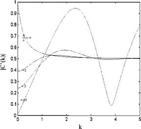
Loewy’s approach applied to a single blade rotor causes the unsteady lift to increase or decrease depending on the reduced frequency. In Fig. 3.10 given is the change in the amplitude of the Loewy function with h/b and k.

So far we have examined the response of a simple harmonically oscillating airfoil in a free stream or in a returning wake. Now, we can study the unsteady aerodynamic response of an airfoil to its arbitrary motion or to an arbitrary external excitation.

Simple Harmonic Motion

In the previous section we have obtained the lifting pressure coefficient in Laplace transformed domains. In order to express the pressure coefficient in time domain we have to invert Eq. 3.23 either with the Bromwich integral or use some other technique for some type of time dependent motions. One of the special types of motion is a simple harmonic motion of the airfoil for which we can invert 3.23 directly. Let us now find the lifting pressure coefficient, sectional lift and moment coefficients for an airfoil which undergoes a simple harmonic motion. If we let za be the amplitude and ю be the frequency of the motion then the equation of the motion for the chordline in its exponential form reads as

Za(x, f)=Za(x)e‘-t (3.25)

According to Eq. 2.20 the downwash expression becomes

w(x, t) = Oza + и-Х = Шa + uOx вш = W(x)eixt (3.26)

In Eq. 3.26 the complex downwash amplitude is defined as

W (x) = iXZa + U-0^

The za(x) is a real valued function of x in Eq. 3.25, whereas in 3.26 the amplitude of the downwash, w(x) expression becomes a complex function. That is when the flow is unsteady there is a phase difference u between the motion and its response as a downwash.

This phase difference is somewhat a measure of the unsteadiness and can be represented in the complex plane as shown in Fig. 3.7.

Let us compare the two downwash expressions, the Laplace transformed one, 3.20, and the simple harmonic one, 3.26. The comparison shows that there is a resemblance between the variables (s) and (ію). On the other hand, the nondi­mensional parameter (sb/U) of pressure coefficient can be identified with another nondimensional parameter i(bm/U) = i k, where k = Ью/U is the previously defined reduced frequency. We can now give a physical meaning of reduced frequency as ‘number of oscillations in radians per half chord travel of the airfoil’. Hence, the reduced frequency is regarded as the nondimensional measure of the unsteadiness.

Подпись: Cpa (X*, k) Подпись: 4 /1 -X* r - 1 + x* -1 4 + -[1 - C(k) — Simple Harmonic Motion

Instead of the variable (sb/U) of Eq. 3.23, if we use (ik) then for the amplitude of lifting pressure coefficient we obtain

(3.27)

Подпись: CPa (x*; k; t) Simple Harmonic Motion Подпись: (x*; k)eiXt Подпись: (3.27a)

The time dependent form of it reads as

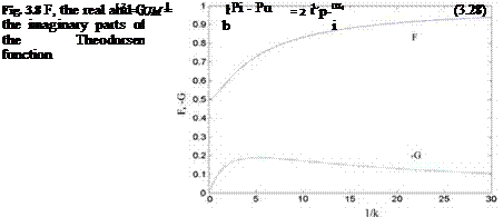
The Theodorsen function, C(k) = F(k) + i G(k), in the last term of Eq. 3.27 is the complex function of the real valued reduced frequency k. In Fig. 3.8, shown is the graph of the real and the imaginary parts of the Theodorsen function in terms of 1/k.

Equations 3.25, 3.26 and 3.27-a are expressed in their exponential terms for their time dependency. This means because of their different amplitudes there is a phase difference between the motion, the downwash and the corresponding lifting pressure coefficient.

Fig. 3.7 Phase difference u between the motion and the downwash

image50

The sectional lift and moment coefficients of a profile now can be found by integrating the lifting pressure coefficient along the chordline, i. e. the lift coeffi­cient becomes

Подпись: m Simple Harmonic Motion

and the moment coefficient with respect to mid chord reads as

Подпись: ci = aemt Подпись: Cl Подпись: - 2 CPadX* Подпись: and Simple Harmonic Motion Simple Harmonic Motion Simple Harmonic Motion Подпись: 2 CpaX*dx*

In Eqs. 3.28 and 3.29, the positive lift is defined as upwards and the positive moment is defined as the leading edge up. Accordingly, the simple harmonic change of the aerodynamic coefficients read as

Подпись: Ci(k) Подпись: 2C(k) Simple Harmonic Motion Подпись: і + n* w(f)df і - n* U Подпись: 2lk Simple Harmonic Motion Подпись: 7iw (n*)dn* U

After performing the integrals, the coefficients in terms of the amplitude of the downwash become

Подпись: 11 1 + n* w(f)df , „ f W* U + 2 1 -1 n n U
Подпись: -[1 + C(k)} 1 + ik j J~1 -1
Подпись: 1 + n* n*w(nw 1 - n*n и
Подпись: cm (k)

(3.30a, b)

Подпись: CT = kim{Q(k)} Simple Harmonic Motion Подпись: 1 + n* w(f)df 1 - n* и Подпись: (3.31a)

The integrals of Eq. 3.30a, b with (ik) as the coefficients are the noncirculatory terms which are the apparent mass terms. The expressions of the aerodynamic coefficients can give us the quasi steady forms if we take the limits while the reduced frequencies go to zero. The limiting process yields

Simple Harmonic Motion Подпись: limfcm (k)} k!0 Подпись: 1 + n* w(n*)dn* 1 - n* и Подпись: 1 + n* «wnw 1 - n*n и (3.31b)
image51 image52

and

Simple Harmonic Motion Подпись: (3.32a, b)

We can express the unsteady forms of the coefficients in terms of the quasi steady coefficients as

The aerodynamic coefficients given by Eqs. 3.32a, b give us the relation between the quasi steady and the quasi unsteady coefficients in terms of the Theodorsen function as well as the contributions coming from the apparent mass terms. If we consider only the circulatory terms, the ratio of the quasi unsteady lift to the quasi steady lift is given by the Theodorsen function which measures also the phase difference between the two coefficients as the effect of the circulatory wake term. Another significance, attributable to the Theodorsen function is as follows. If we know the quasi steady coefficients from the experiments or through some other means we can obtain the corresponding quasi unsteady coefficient by multiplying the former by the value of Theodorsen function at desired reduced frequency.

Let us now give some examples ranging from simple to more complex flow cases.

Example 2 Vertical oscillation of a flat plate in a free stream.

The profile motion is in z direction with amplitude za, therefore the motion for the equation reads as za(x, t) = zaelxt. The corresponding downwash becomes

w(x, t) = lmZaelxt = welxt; (w = ixZa) ■

Simple Harmonic Motion

As easily seen, the amplitude of downwash differs from the motion with coefficient im, which shows that the phase difference between them is 90°. Substituting the downwash expression in 3.31a, b we have

cl = —2nlkz*aC(k) + nk2z*a and cm = —nikz*aC(k):

From aerodynamic coefficients we observe that the apparent mass contributes to the sectional lift coefficient but not the moment coefficient.

Let us now analyze the response of a thin airfoil to pitch oscillations about its midchord.

image53

Example 3 Flat plate pitching about its midchord.

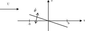
As seen from the picture, the chordline equation of a pitching airfoil reads as za(x, t) = —Ox = —x()elx‘, and the corresponding downwash

w(x, t) = —Ox — UO = (—imbx* — U)0e, xt■

Simple Harmonic Motion

Considering the steady term Uh also, Eq. 3.31a, b gives cf = ткв + 2пв and c®s = пв. For the unsteady motion

hl = (пікв + 2пв)С(к) + пікв and cm = пікв—————————- Ь пвЄ(к)+ —к2.

2 8

Подпись: x
image54

The last terms in both amplitudes indicate the effect of apparent mass terms. We have so far seen the single degree of freedom problems. As a more complex problem we are going to study a two degrees of freedom problem where the airfoil translates vertically and rotates around a fixed point.

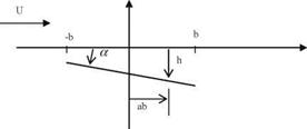
Let the vertical translation in z be h = heia>‘, and the rotation about the point ab (where a is a nondimensional number) be a = aeixt as shown in the Figure. The equation of the profile reads as

za(x, t) = aba — h — ax, and the downwash

Simple Harmonic Motion Подпись: a+ I 2+a Подпись: 1— 2с (к)

w(x, t) = {iwh(ab — x) — h] — Ua}eixt. If we use the downwash expression in 3.32a, b we obtain the amplitude for the unsteady coefficients we obtain

(3.33 —a, b)

The moment coefficient here is computed with respect to mid chord. The moment coefficient about any point a using the coefficients from 3.33a, b becomes

cma cm Ь cia

Example 4 Find the sectional lift coefficient change for an airfoil pitching about its quarter chord with the angle of attack a = 10o sinrot, and the reduced frequency к = 0.1.

Solution: Let us consider the terms of 3.33 which depends on angle of attack only. For the simple harmonic motion for к = 0.1 the sectional lift coefficient reads as

Here, the angle of attack changes with a sinus term. Therefore, we have to write the relation between the sinus term and the exponential form of the angle of attack.

Let us expand the exponential form with Euler’s formula as follows

aeixt = acosxt + lasinxt

As seen from the expanded form, the contribution to the lift coefficient will be from the second term which is imaginary and contains sinus term. Therefore, the contribution will come from the second term of Eq. 3.33a, b which is also imaginary. The general expression of the lift coefficient becomes

cielxt = (clR + їсц )(cosxt + Isinxt)

= ClR cosxt — Сц sinxt + l(clR sinxt + Сц cos xt)

Hence, the imaginary part which we are interested, is

(clR sinxt + clI cosxt)

If we form the linear combination with real and imaginary parts of the sectional

Lift coefficient then we obtain

Cl = clR sinxt + Сі/ cos xt = 0.92832sinxt — 0.0428cosxt
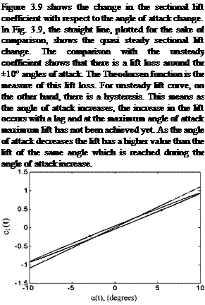
Подпись: Figure 3.9 shows the change in the sectional lift coefficient with respect to the angle of attack change. In Fig. 3.9, the straight line, plotted for the sake of comparison, shows the quasi steady sectional lift change. The comparison with the unsteady coefficient shows that there is a lift loss around the ±10° angles of attack. The Theodorsen function is the measure of this lift loss. For unsteady lift curve, on the other hand, there is a hysteresis. This means as the angle of attack increases, the increase in the lift occurs with a lag and at the maximum angle of attack maximum lift has not been achieved yet. As the angle of attack decreases the lift has a higher value than the lift of the same angle which is reached during the angle of attack increase. Fig. 3.9 Unsteady sectional lift coefficient change

Here, The Theodorsen function was utilized for the analysis of unsteady flows about plunging-heaving thin airfoil. The comparison between the theoretical and the experimental studies are given by Leishman for The NACA 0012 airfoil at low Mach and high Reynolds numbers for the reduced frequency range of

0. 07 < k < 0.4, where the lift coefficients are in good agreement. The disagree­ment for the moment coefficients on the other hand, can be remedied by slightly moving the aerodynamic center in front of the quarter chord. In addition, Leish – man gives the experimental results for an airfoil pitching about its quarter chord for the reduced frequency range of 0.05 < k < 0.6. The experimental and the theoretical values at low Mach numbers and not so large reduced frequencies agree well.

Unsteady Flow

Our unsteady analysis of the flow is going to be similar to that of steady flow except now, we are going to assume a vortex sheet strength ya = ya (x, t) as the function of two variables x and t. There will also be continuous vortex shedding to the wake from the trailing edge because of having unequal vortex sheet strength from the lower and upper surfaces right at the trailing edge. Since there is a vortex sheet at the near wake there will be a velocity field induced by it as well as its effect on the bound vorticity. Let us now see the effect of the both vortex sheets on the induced downwash with the aid of Fig. 3.6.

Denoting the near wake vortex sheet strength with yw, the downwash w at z = 0 with the aid of Biot-Savart law

b 1

Подпись:Подпись:1 f Уа(П; t)dn _ 1 f Cwfe t)dn

2p x _ П 2p x _ П

_b b

The first integral at the right hand side of Eq. 3.9 is singular but the second integral is not. We can write the equivalent of the second integral in terms of the bound vortex using the unsteady Kutta condition.

Подпись: CPa (X)
Подпись: Pi - Pu 2 P1U2
Подпись: 0, x > b

In case of steady flow we have expressed the Kutta condition as the zero velocity at the trailing edge or no vortex sheet at the near wake or no pressure difference at the wake region. In case of unsteady flow, however, there is a nonzero velocity at the trailing edge and non zero vortex sheet at the near wake. Therefore, the unsteady Kutta condition is expressed as the zero pressure differ­ence at the wake. Accordingly, the unsteady Kutta condition is more restrictive, and therefore in formulation it reads

Подпись: CPa (X) Unsteady Flow Подпись: «+§ Подпись: M 0x Подпись: M 0x

In terms of perturbation potential, using Eq. 2.21 it becomes

Подпись: Cw(X; t) = U'(X; 0+; t)- U'(X; 0 ; t)= ( ^ - ^ Подпись: w Подпись: xb

Equation 3.1 gives the relation between the perturbation potential and the vortex sheet strength for the steady flow case. Similarly, we can write this relation for the unsteady flows at any time t as follows

The integral relation between the perturbation potential and the perturbation velocities are

X X X X

/U = J 0/rdn = j UUdn ve /i = J 0/dn = j uidn

—1 —1 —1 —1

Подпись: /u Подпись: x b x —b —b b bx

Before the leading edge we do not have any velocity discontinuity between upper and lower surfaces therefore, for x < —b there is not any contribution to the integrals evaluated for x > b

Подпись: 0 0t Unsteady Flow

If we take the derivatives of the above expression with respect to t and x, the unsteady Kutta condition becomes

The first integral at the left hand side is evaluated to the bound vortex Га (t). Hence, the final form of the unsteady Kutta condition reads

X

~ГГ + 0J t’)dn + U ^ ^=0 (3’10)

b

Equation 3.10 is an integro-differential equation which relates the bound vortex to the vortex sheet strength of the wake. Our aim here is to eliminate the wake vorticity appearance from the downwash expression so that all the terms in Eq. 3.9 are expressed in terms of the bound vortex sheet strength. If we transform time coordinate to some other coordinate and then differentiate the result with respect to x we can succeed to do so. Let us now take the Laplace transform of Eq. 3.10, remembering the definition and a property of the Laplace transform (Hildebrand

1976) ,

Lff(t)g e slf(t)dt = я» and L{~dr}= sf(s)~/(0+)’

0

The Laplace transform of 3.10 then becomes

X

sCa + J syw(n, s)dn + UCw(x, s)= 0 (3:11)

b

Here, at t = 0+, Га and yw (x) are both zero. If we take the derivative of Eq. 3.11 with respect to x, the first term becomes zero and we end up with a first order differential equation in x.

sCw(-T s) + U0xCw(x; s)= 0 (3’12)

The solution to this equation becomes

Cw(-T s) = B(s)e U’

In order to determine B(s) we utilize the value of 3.10 at x = b. This gives

sC

sfa + Uyw(b, s) = 0 and yw(b, s) = B(s)e—U combined B(s) = — aeU:

substituting B(s) gives

Подпись: Cw(x; s)sCae U(x b) or with x* = x/b U ‘

Unsteady Flow

a

U


Unsteady Flow

1)


Cw(x* ; s)


(3:13)


Unsteady Flow

Now, we can express Eq. 3.9 in non dimensional coordinates and in its Laplace transformed form as follows


, 1 П. (1’. Aif 1 [US’, АЧ*

w(x. s) = —p – 2 x’ — n

-1 1

1 _ 1 ,

= _± Уа(1’. S)dl* sCa f е-її dS

2p x’ — 1’ 2nU x’ — 1’

11


(3.14)


Equation 3.14 can be rearranged to give a Fredholm type but non homogeneous equation as follows


Unsteady Flow

(3.15)


In Eq. 3.15 the second term at the right hand side of the equation is the non homogeneous term. Inverting the integral as described in Appendix 1 we obtain


Unsteady Flow
Unsteady Flow
Unsteady Flow
Unsteady Flow Подпись: 1 + f dn 1 - f x* — f Unsteady Flow Подпись: 1 + n* dn 1 — n* n* — k

and evaluate the inner integrals as follows

Unsteady Flow

Adding those two together

Подпись: 1 J 7a(x*; s)dx* —1 Подпись: Ca b image46

In Eq. 3.16, the bound vortex Га plays the role of a coefficient at the right hand side to determine the bound vortex sheet strength itself. Therefore, if we integrate 3.16 with respect to full chord we obtain the bound vortex also. In non dimensional coordinates the integral reads as

image47

If we interchange the order of integrals at the right hand side, we can then perform the integrations with respect to x* and obtain the following equation Га in terms of the downwash

The second term at the right hand side of Eq. 3.17 can be integrated with respect to k. The resulting integral is expressible as an Hankel function of second

kind in terms of the complex argument (-isb/U). A useful relation between the Bessel functions and the Hankel functions are provided in Appendix 5.

Unsteady Flow Unsteady Flow

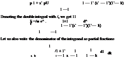
Denoting the integral at the second term of Eq. 3.17 by I2 with the help from Theodorsen, we obtain

1

and write the result for the bound circulation in terms of the downwash

Подпись: — s sb гa eU = ■ a U Подпись: 4/pПодпись: HПодпись: s)dn*image48(3.19)

The relation between the downwash w and the time dependent motion of the airfoil was given by Eq. 2.20. We need the Laplace transformed form of Eq. 2.20 to implement in 3.19, which is

w(X*, s) = sZa(X*; s)+ +bO0^Za(X*, s)] (3.20>

At this stage, we can use 3.20 in 3.19 and obtain the bound circulation in s domain. After inverting the result to time domain by inverse Laplace transform, we can get the time dependent bound circulation and the lift. For more detailed analysis, the relation between the lifting pressure coefficients and the bound vortex sheet strength we obtain

x

. . 2 0 2 0/ 0/ 2 0 2 cPa(x,,) = UT* 05(/-/’) + U?(aT – = U 0,J ‘!-(i-,)dn + v>a(x, t)

-b

(3.21)

Подпись: CPa (X*; s) Подпись: 2 U Подпись: sb U Подпись: x* f Ca(n* ; s)dn + Ca (x*; s) 1 Подпись: (3.22)

We can now take the Laplace transform of Eq. 3.21 which in s domain reads as

Substituting Eq. 3.16 in 3.20 and integrating the fist term on the right hand side we obtain

Unsteady Flow
(3.23)

Functions F and G are real although their arguments are imaginary. The The – odorsen function takes the value of unity for s approaching to zero, i. e.

Подпись: 1й C ‘U

Подпись: 1 + n* 1 w (n*)U n* 1 - n* x* - n* d n

Подпись: 1 4 /1 - x* p 1 + x* =1
Подпись: hm{cp (x*, s)} s^0

which simplifies the pressure coefficient for s = 0 as follows

This term is called the quasi steady pressure term and it is equivalent to the steady pressure term.

Подпись: hm{U2cp (x*, s)} Unsteady Flow

As is well known for steady flow that the zero free stream means zero lift. For unsteady flow however, during the vertical translation of the airfoil we expect to have a lift generation even under zero free stream. We can show this with a limiting process performed on the second term of Eq. 3.23 with multiplying the term with U2 and letting U go to zero as follows.

From the last line we see that the vertical force is proportional with s2za. Since za is independent of s then inverse Laplace transform of s2za gives us

Подпись: efza 0f2 L {s2Za}

The last expression shows that even at zero free stream speed there exists a lifting force which is proportional to the acceleration in vertical translation. This force is an inertial force generated by the motion of the profile and it is called the apparent mass. Since there is no circulation attached to it, it is also called non circulatory term.

The third term at the right hand side of Eq. 3.23 is the circulatory term due to wake vortex sheet. For unsteady flows we do not have to take into consideration all three terms of Eq. 3.23. Depending on the unsteadiness we can ignore some of the terms in our analysis depending on the accuracy we look after. Now, we can discuss which term to neglect under what physical condition. According to a classical classification:

(i) ‘Unsteady aerodynamics’: All three terms are included. Motions with about 40 Hz frequencies are analyzed by this approach.

(ii) ‘Quasi unsteady aerodynamics’: The apparent mass term is neglected. Motions with 5-15 Hz frequencies are analyzed using this approach.

(iii) ‘Quasi steady aerodynamics’: Motions with frequency of 1 Hz or below is analyzed using the circulatory term only.

After making this classification, we can now derive a formula for the lifting pressure coefficient for simple harmonic motions and obtain the relevant aero­dynamic coefficients such as sectional lift and moment coefficients.

Steady Flow

Once the Kutta condition is satisfied, the picture of the flow field remains the same, which means the flow is steady. In a steady flow around airfoil as stated before, there is a bound vortex and the starting vortex. Since the starting vortex is located far away from the profile it has practically no effect. The only vortex in effect is the vortex sheets of upper and lower surfaces. If the thickness of the profile is <12%, it is assumed that the upper and lower surface vortex sheets are close enough and they add up to a single vortex sheet which is easily modeled as a vortex sheet of strength ya. That means, for yu showing the upper surface vortex sheet strength and c showing the lower surface then they add up to

Ca(x) = Cu(x) + Cl(x)-

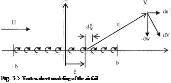
With this mathematical modeling the Kutta condition and the Laplace’s equations, Eq. 2.15, are both satisfied. Figure 3.5 shows the vortex sheet modeling an airfoil with its chord is in line with x axis and has length of 2b.

According to the Biot-Savart law (Kuethe and Chow 1998), the vortex sheet of strength ya(x) and length di induces the differential velocity of dV at a point (x, z).

Ca (x

2nr

The x and z components of dV reads as

Steady Flow

du’ = dV sine, dw = —dV cos в, sinh = z/r and cosh = (x — <f)/r. The induced components, from Fig. 3.5, can be expresses as

At this stage, it is essential to note that there is no contribution to the pertur­bation velocities from the free stream speed. If we closely examine the sign of z in the integrands of the above integrals we see that u is antisymmetric and w is symmetric. That is

u (x, 0+) = — u'(x, 0 ) and w(x, 0+) = w(x, 0 )

Подпись: Fig. 3.5 Vortex sheet modeling of the airfoil

Let us now find the relation between the perturbation speed u and the vortex sheet strength as follows

Steady Flow

The rectangle shown with the dimensions of dx. dz has the circulation given as

ya(x)dx = [U + u'(x, 0+)]dx — (w + dw)dz — [U + u'(x, 0—)]dx + wdz = [u'(x, 0+)— u'(x, 0—)]dx — dwdz

Neglecting the second order terms we get

ya(x) = u'(x, 0+) — u'(x, 0—) = 2u'(x, 0+) (3-1)

Equation 3.1 tells us that the perturbation speed in x direction is given by the local vortex sheet strength. In addition, the physical meaning of a vortex sheet strength is that it is the discontinuity of the velocity between the upper and lower surfaces.

Let us now find the downwash at the surface, z = 0,

b

Подпись: w(x, 0)Подпись: (3-2)1 Уд(ПЖ

2p x — П

—b

The integral given in Eq. 3.2 has an integrable singularity at x = П. These type of singular integrals are called the Cauchy type integrals and in Appendix 3 we show how to evaluate this type of integrals at the complex plane.

Подпись:Подпись: (3-3)

Steady Flow

Equation 3.2 is an integral equation if we consider ya(x) as unknown function and w(x) as the known downwash. This type of integral equation is called Fred­holm type and its inversion is provided in Appendix 2. Accordingly, if we use the non dimensional coordinates x* = x/b and П* = П/b and utilize the Eq. 3a, b of Appendix 3 we obtain the inverted form of 3.2 as

Equation 3.3 satisfies the Kutta condition at the trailing edge because it has a zero value as x* takes the value of 1. The integrand in the equation is obtained from Eq. 2.20. In case of steady flows the downwash is function of angle of attack, free stream speed U and camber of the airfoil.

After finding an expression for the bound vortex sheet we can now relate it with the lifting pressure coefficient. For the steady flow the pressure coefficient was given by Eq. 2.21 as

cp(x)

Подпись: c Steady Flow Подпись: (3.4)

Let us now find the lifting pressure cPa as the pressure difference between the lower and upper pressures

Подпись: cpa(x) Подпись: 2Ca (x) u Подпись: (3.5)

The lifting pressure coefficient can be expressed in terms of the upper and lower perturbation speeds. With the aid of Eq. 3.1

According to Eq. 3.5, the lifting pressure coefficient behaves similar to that of the vortex sheet strength. This behavior can be seen with a limiting process applied at the leading and the trailing edges as follows

lim [cpa(x)] = lim — and lim[cpa(x)] = lim — = 0

x!-b £—0 e x – Ь £!0

With these limiting values we see that the singular lifting pressure at the leading edge becomes zero at the trailing edge. Now, the sectional lifting force i can be found using Eq. 3.5 with integration

b b b

1 = 2P“u2 / cpa (x)dx = Pi U j Ca(x)dx where Ca(x)dx (3.6)

Подпись: bПодпись: bb

gives: І = р? иГа which is known as the Kutta-Joukowski theorem which gives the lifting force acting on a vortex immersed in a free stream speed U and has a strength Г (Kuethe and Chow 1998). If we combine Eqs. 3.3 and 3.6 we obtain the bound vortex sheet strength given in terms of the downwash distribution as follows.

1

Подпись: /1 + Т 1 - f Подпись: (3.7)Га = -2b J -1

Example 1 For an airfoil at an angle of attack a find (i) sectional lift coefficient, (ii) moment coefficient and (iii) center of pressure and aerodynamic center.

Solution: This the flat plate immersed in a free stream of U with angle of attack a as shown in the following figure.

Equation 3.8 for x0 = 0 gives

Cmo pa

(iii) The center of pressure xCP in terms of this moment reads as

m0

xcp — x0 i

in general. Using the result of (ii) for the flat plate

b

Подпись: 2

image44

xcp

This result proves that for a symmetric thin airfoil the center of pressure is located at the quarter chord point. Now, let us find the aerodynamic center xac.

By definition the aerodynamic center is the point where the sectional moment is independent of the angle of attack a. With Eq. 3.8 and 9mo/9a = 0 gives us xac = —b/2. This again proves that the aerodynamic center and the center of pressure are at the same points for a symmetric thin airfoil.

Hitherto, we have given the formulation for the steady flow for which flow conditions remain the same with respect to time. When the flow conditions change slowly with time, we can assume quasi steady flow as it happens for a slow change in the angle of attack so the force and the moment change in phase with the angle of attack. The picture is not the same when the changes are fast because we observe a lag between the motion and the response of the airfoil to the motion. Let us now extend our external flow model for the unsteady treatments which gives us the lag as well as the deviations from the steady flow conditions because the presence of near wake effects.