Category HELICOPTER AERODYNAMICS

Blade Thrust and Its

Подпись:Azimuthal Variation

Подпись:During rotation of the main rotor in the forward flight regime, there is continuous variation of the blade position relative to the flight velocity vector or the velocity vector of the undisturbed flow approaching the main rotor. This situation in­fluences the nature of the flow over the blade and the forces which arise, the reason for many phenomena which special concept is introduced to

The azimuth, or the angle of the azimuthal position of the blade, is the angle between a reference line and the blade longitudinal axis at a given moment of time (Figure 29).

It is customary to take as the reference line the blade longitudinal axis when the blade is positioned directly aft of the main rotor hub.

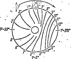
The azimuth is reckoned from 0 to 360° in the direction of rotation of the main rotor and is represented by the letter p. The blade traveling from /44 from the 0° azimuth to the 180° azimuth is called the advancing blade. The blade travelling from the 180° azimuth to the 360° azimuth is called the retreating blade. The concepts of "advancing" and "retreating" blades are associated with the variation of the direction of the undisturbed stream approaching the blade.

In the case of the advancing blade, the undisturbed flow created by helicopter flight is directed at some angle to the blade leading edge, while

in the case of the retreating blade, this flow is directed at the trailing edge, increases the vibration of the main rotor and the variation of the blade thrust as a function of azimuth, and reduces the main rotor thrust in the forward flight regime. The main rotor blade has a section of the lifting surface removed in the root region in order to reduce these undesirable phenomena (Figure 30). Increase of the cutout reduces the influence of reverse flow, but increases the root losses and, consequently, the magnitude of the thrust in the forward flight regime. An optimal size of the root cutouts is established for each main rotor.

Подпись:The thrust of an individual blade can be found from the same formula used to obtain wing lift

rb = S5b^TF2’

where C is the blade thrust coefficient;

Tb

S, is the blade planform area; b

W is the resultant blade tip velocity.

The blade thrust coefficient depends on its shape and incidence angle;

consequently, for a fixed pitch ф the quantities C and S are constants.

b

Then for constant air density the blade thrust will vary similarly to the variation of the resultant velocity over the blade.

In the forward flight regime the blade thrust reaches its maximal value at the 90° azimuth, since in this case the resultant velocity over the blade is maximal. Conversely, at ф = 270° the blade thrust is minimal, since the resultant velocity is least at this azimuth (see Figure 31c).

How can the maximal flight speed of the helicopter be increased?

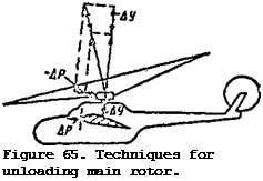
In order to avoid blade tip stall at the 270° azimuth with increase of the forward speed, it is necessary to reduce the main rotor pitch. But this leads to reduction of the thrust and creation of a deficiency of the lift force (-AY) and of the propulsive force (-ДР) (Figure 65). In order to avoid these phenomena, use is made of an auxiliary wing, which creates the additional lift force ДУ.

The additional propulsive force AP necessary to increase the speed is /98 created either by increasing the engine thrust or by the thrust of additional propellers. Helicopters with an additional wing and additional propellers are called compound helicopters. In these helicopters there is an unloading of the main rotors such that they can operate with lower incidence angles, and blade stall occurs at higher speeds. Helicopters of this type include the

Mi-6 and Kamov’s prop-wing design with side-by-side rotors. The speed of the compound helicopters reaches 400-450 km/hr. However, they also have draw­backs : increased structural weight

Подпись: Figure 65. Techniques for unloading main rotor. and increased parasite drag as a result of the slipstream from the main rotor flowing over the wing.

This situation is particularly charac­teristic for the vertical flight regimes with low horizontal velocities.

Helicopter Static Stability

General analysis of static stability. Static stability is the capability of the helicopter to restore disturbed equilibrium by itself after removal of the factors causing this disturbance. Static stability is attitude stabil­ity. The helicopter will be stable if after equilibrium is disrupted stabili­zing moments develop on the helicopter, i. e., moments directed to restore the previous attitude. Static stability is amplified as a result of damping moments. A damping moment is one which is directed opposite the oscillatory motion of the helicopter about some axis. The difference between the stabili­zing and damping moments is that the former arises as a result of equilibrium disruption and acts after the termination of this disruption. The damping moment acts only in the process of equilibrium disruption and is directed opposite the deviation.

If during and after equilibrium disruption, moments appear on the helicopter which deflect it still further from the previous attitude, such moments are termed destabilizing. The helicopter on which destabilizing moments arise is termed statically unstable. The helicopter on which no moments arise during and after the equilibrium disruption process has indiffer­ent equilibrium and is termed statically neutral.

The factors which disturb equilibrium are:

(1) unsettled state of the air ("turbulence");

(2) random deflection of the control levers;

(3) failure of some part of the helicopter;

(4) change of the eg location.

Characteristic of helicopter equilibrium is the intimate interconnection of the individual equilibrium modes with one another. For example, if longitudinal equilibrium is disrupted, i. e., if the helicopter rotates about the transverse axis, the main rotor angle of attack changes. This involves a change of the thrust force and the reactive moment of the main rotor. The change of the reactive moment disrupts the directional equilibrium. Disrup­tion of directional equilibrium leads to change of the tail rotor thrust force /160 and change of the moment of this force relative to the longitudinal axis, which means disruption of the helicopter transverse equilibrium. The intimate interconnection among the equilibrium modes requires constant action from the pilot, directed toward restoring the disrupted equilibrium, i. e., helicopter control becomes more complicated. Does the helicopter have static stability?

In order to answer this question we must examine the static stability of the main rotor, the static stability of the fuselage, and the effect of the stabil­izer and tail rotor on the static stability.

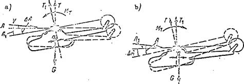
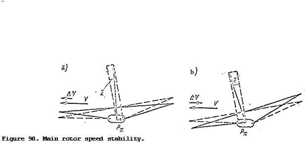
Main rotor static stability with respect to velocity. When the helicopter equilibrium is disrupted, two motion parameters of the main rotor change: the flight velocity and the angle of attack. Let us assume that the helicopter is performing horizontal flight at the velocity V (Figure 98a). For some reason the flight velocity is increased by AV. As a result there is an increase of the flapping motions of the blades, the main rotor cone axis is deflected aft from the previous position, which is shown dashed in the figure, by the angle є. The tilt of the coning axis leads to the appearance of the force P, directed opposite the flight direction. Under the influence of this force the main rotor velocity will decrease.
Подпись: Figure 98. Main rotor speed stability.
If the flight velocity is reduced by AV (Figure 98b), the cone axis is deflected forward, the force Px in the direction of flight develops, and the flight velocity will increase. The conclusion is that the main rotor has static stability with respect to velocity.

Main rotor static stability with respect to angle of attack. The heli­copter is flying horizontally and the main rotor angle of attack is A. Under the influence of a vertical air current, the helicopter drops its nose and the main rotor angle of attack is reduced by AA (Figure 99a). Prior to dis­ruption of equilibrium, the main rotor thrust force vector passed through the helicopter center of gravity and the moment of the thrust force was zero.

Upon disruption of the equilibrium, the thrust force vector T is deflected forward and the moment Mz = T^a develops relative to the helicopter transverse axis; this moment rotates the helicopter and the main rotor in the direction to reduce the angle of attack. Consequently, this moment will be destabili­zing.

If for some reason the main rotor angle of attack is increased (Figure 99b), the thrust force vector tilts aft and a nose-up moment M^ = T^a is created, which causes the angle of attack to increase. A destabilizing thrust moment is created. The conclusion is that the main rotor is unstable with respect to angle of attack.

Helicopter Static Stability

Figure 99. Main rotor angle-of-attack stability.

Helicopter fuselage static stability. The fuselage has the second largest influence, after the main rotor, on the static stability of the helicopter.

The fuselage of the single-rotor helicopter has static instability about all three axes. A small stabilizer is installed at the aft end of the fuselage to improve longitudinal static stability in horizontal flight. In the hover regime and in flight at low velocity the stabilizer has practically no effect on longitudinal static stability. But with increase of the flight velocity and with reduction of the angle of attack, the longitudinal instability present in a hover decreases, and at negative angles of attack the fuselage plus stabilizer has longitudinal static stability. Thus, the fuselage of the Mi-1 has static stability at angles of attack from -10 to -2°. At positive angles of attack, the fuselage has indifferent longitudinal equilibrium.

The helicopter stabilizer is controllable. Stabilizer control is accomplished with the aid of the collective-throttle lever. When this lever is moved upward, main rotor pitch and stabilizer incidence angle are increased. The controllable stabilizer makes it possible to tilt the helicopter fuselage to a negative angle at the maximal slight speed. If the stabilizer angle were constant, a large negative lift force would develop on the stabilizer at a negative angle of attack, and this force would create a large nose-up moment to prevent tilting of the fuselage. When the rotor pitch is decreased the

stabilizer incidence angle becomes negative and a nose-up moment is developed, which aids in transitioning the main rotor into the autorotative regime. The main rotor angle of attack becomes positive, and as a result of the increase /162 of the angle of each blade element the rotor rpm increases.

The tail rotor also affects the fuselage static stability. The fuselage acquires directional stability as a result of the tail rotor. Thus, when directional equilibrium is disrupted, if the helicopter turns to the right for example (with right-hand rotation of the main rotor), the angles of attack of the tail rotor blade elements increase, and the tail rotor thrust force increases by ДТ. The moment of the tail rotor thrust also increases and equilibrium is restored.

If the helicopter turns to the right, the blade element angles of attack will decrease and therefore the thrust will decrease. The tail rotor moment becomes less than the main rotor reactive moment, and this leads to restoration of the equilibrium.

Since the tail rotor is mounted above the helicopter longitudinal axis and creates a transverse thrust moment, this leads to increase of the trans­verse static stability. Therefore, the tail rotor gives the fuselage directional and transverse static stability.

The conclusion is that the helicopter has slight static stability in horizontal flight and indifferent equilibrium in hover and in the other vertical flight regimes.

The static stability of twin-rotor helicopters differs somewhat from that of the single-rotor helicopter. The two-rotor helicopter with tandem arrangement of the rotors has considerably greater longitudinal static stability, while the two-rotor helicopter with side-by-side arrangement has higher transverse stability. This is explained by the variation of the thrust of the lifting rotors when equilibrium is disrupted.

Effect on helicopter static stability of horizontal hinge offset. If the main rotor huh has offset horizontal hinges, the horizontal hinge moments have considerable effect on the longitudinal and transverse static stability of the helicopter. The larger the horizontal hinge offset and the higher the main rotor rpm, the larger the main rotor damping moment and the greater the helicopter static stability. Thus, increase of the static stability is achieved by increasing the horizontal hinge offset. The appearance of the damping moment is explained by the gyroscopic properties of the main rotor.

As is well known, the basic property of the gyroscope is its ability to maintain the attitude of its axis of rotation fixed in space. This property shows up more strongly, the larger the mass and the higher the rpm of the rotating body. What effect does the gyroscopic effect of the main rotor have on the behavior of the helicopter? We shall use an example to investigat this question.

Подпись: /163Let us assume that the longitudinal equilibrium of the helicopter has been disturbed and it has started to rotate about the transverse axis in the nose-
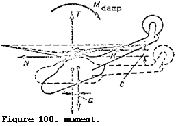
Подпись: Figure 100. moment. down direction (Figure 100). In view of its gyroscopic properties the main rotor will lag behind the helicopter rotation, therefore the main rotor hub axis is deflected from the cone-of – rotation axis. The horizontal hinge moment = Nc will be directed

Подпись: Main rotor dampingopposite the tilt of the helicopter; therefore it will be a damping moment. When equilibrium is disrupted, the helicopter will rotate relative to the stationary cone-of-rotation axis of the main rotor as a result of the gyroscopic effect. And this means that the helicopter center of gravity will also displace together with the helicopter

A


relative to the cone-of-rotation axis (shown dashed in Figure 100). The result is the formation of the thrust moment = Та. The damping moment will be equal to the sum of the two moments + Hj, = Nc + Та. The

damping moment will be larger, the. higher the main rotor rpm, the larger the horizontal hinge offset, and the lower the position of the helicopter center of gravity, i. e., the larger the vertical eg displacement. The arm a and the thrust force moment will increase with increase of the distance Y from the hub rotation plane to the center of gravity.

Azimuthal Variation of Rotational Resistance Forces and Reactive Torque

Both the rotational resistance forces and the thrust forces of the blades vary azimuthally as a function of the resultant flow velocity over the blades.

Azimuthal Variation of Rotational Resistance Forces and Reactive Torque

Figure 44. Blade element angle of attack diagram.


Azimuthal Variation of Rotational Resistance Forces and Reactive Torque

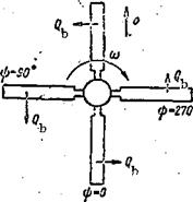
Figure 45. Blade rotational resis­tance forces at different azimuths.


The resistance to rotation of a single blade reaches its maximal value at the 90° azimuth and minimal value at the 270° azimuth.

At the 0° and 180° azimuths the rotational drag in the forward flight regime is equal to the drag in the axial flow regime, if the main rotor pitch and flight altitude remain the same (Figure 45).

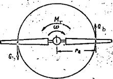
As a result of this variation of the resistance to rotation, there will /61 be azimuthal variation of the main rotor reactive torque from the maximal value when the blades are at the 90° and 270° azimuths to the minimal value when they are located at the 0°and 180° azimuths.

The variation of the reactive torque causes vibration (torsional oscil­lations) with a frequency equal to the main rotor rpm or some multiple thereof.

For two blades at opposite azimuth angles the rotational resistance forces are directed oppositely relative to the rotor diameter. At the 0° and 180° azimuths their sum is zero; however, at the 90° and 270° azimuths the sum of these forces is not equal to zero and is directed opposite the helicopter

flight direction, since is larger at the 90° azimuth than at the ф = 270° azimuth. This force is the profile drag of the main rotor.

Effect of Number of Blades on Main Rotor Aerodynamic Characteristics

Single-blade main rotors are not used because of the high degree of /60

unbalance.

The primary advantage of the two-blade main rotors is the simplicity of the construction. But the two-blade rotor has low solidity and consequently poor aerodynamic characteristics (low thrust coefficient C^).

Increase of the solidity with increase of the area of each blade (by increasing its width) leads to increase of the profile drag and reduction of the main rotor efficiency.

Moreover, the blades of any rotor cannot be made perfectly identical.

They always differ from one another in their characteristics; therefore the overall blade thrust varies in the forward flight regime. The main rotor resistance to rotation will also vary, i. e., the load on the rotor shaft will vary, and torsional vibrations of the shaft, main rotor vibrations, and vibrations of the entire helicopter will develop.

These problems can be resolved by increasing the number of blades. The larger the number of blades, the smaller the amplitude of the main rotor thrust variations and the smaller the azimuthal variation of the rotor torque, i. e., the rotor becomes more balanced. However, at the same time rotor fabri­cation and blade balancing and adjustment become more difficult. On this basis, main rotors with 4-5 blades are most frequently encountered.

Thrust required for various flight regimes and its variation in the different regimes

Answer 1. The thrust required for a given regime is the force necessary to provide flight along the given trajectory at the required velocity. For constant velocity the thrust required is practically the same for horizontal flight, climbing flight, and descending flight.

Answer 2. The thrust required for a given flight regime is the force required necessary to balance the airplane weight and create the propulsive force. In a climb the thrust required will be considerably greater, and during descent it will be considerably less than in the horizontal flight regime.

Answer 3. The thrust required for a given regime is the force necessary to overcome the parasite drag. At a constant speed the thrust required will be the same for horizontal flight, inclined climb, and inclined descent.

Power and Torque Required to Rotate Main Rotor

In order for the main rotor to turn, the action of the reactive torque must be overcome, i. e., driving torque must be supplied to the rotor.

The torque Mt ^ which must be supplied to the main rotor is termed the /22

required torque. In magnitude, it equals the reactive torque — in direction, it opposes the latter

= пі F £ (toR)2 R tor tor 2

where in is the torque coefficient, tor

The torque coefficient is a composite quantity, i. e.,

m = m + m

tor tor tor.

pr і

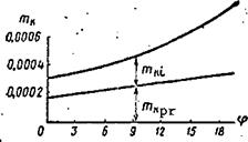
Подпись: where m.Подпись:Подпись: m.Подпись:is the part of the torque coefficient due to profile drag forces. This part depends on the condition of the blade surface, the rotor rpm, and the blade shape; is the part of the torque coefficient due to the induced drag forces and depends primarily on the main rotor pitch (Figure 18).

The formula for the required torque, and also the curve of this torque coefficient versus rotor pitch, makes it possible to conclude that the main rotor required torque will increase with increase of the pitch, rpm, and air density.

We recall that power is work per unit time. The concept of the power required to turn the main rotor can be obtained if we examine the work ex­pended in overcoming the forces resisting the rotation of a single blade, and then the work expended in overcoming the reactive torque of the entire rotor (Figure 19).

The work of a single blade during one revolution of the main rotor is

A,“°b2’V

The main rotor work per second, i. e., the power required, is /23

Power and Torque Required to Rotate Main Rotor

Figure 19. Action of rotational resistance forces.


Power and Torque Required to Rotate Main Rotor

Figure 18. Torque coefficient versus main rotor pitch.


N = A, kn req b s

where к is the number of blades;

n is the rps.

s

Consequently,

N = Q. 2irr_kn req b Q s

since

Q rnk = and 2Ttn. — «),

Q P J

then

Подпись: (IDN = M o) .
req p

Both the power required and the torque required for the main rotor
change with change of the pitch, rpm, and air density. In order to turn the

J


rotor, engine power equal to the power required must be supplied to the rotor shaft. This equality is the condition for constant rpm

N = N sup req

where Ng Is the power supplied to the rotor from the engine.

If the power supplied NgUp > rotor rPm will increase. However,

if N < N the rotor rpm will decrease, sup req r

Vertical Climb

Helicopter flight along a vertical trajectory with constant velocity is

termed the vertical climb regime. The following forces act on a helicopter

in vertical climb (see Figure 53): the helicopter weight force G, the main

rotor thrust force T, and the tail rotor thrust force T.

t. r

In order to balance the tail rotor thrust force, the main rotor thrust force vector must be inclined at the angle 6, which results in the creation of the vertical thrust force component Y and the horizontal component S^.

The steady-state climb conditions will be expressed by the equalities:

Since the force X is small and may be neglected and the force YftS T, the equality Y = G + X can be replaced by the equality T = G. Then the vertical climb conditions will be analogous to the hovering conditions. The condition T = G assures constant helicopter speed in the vertical climb regime./82 The equality Tt r = Ss assures rectilinear flight.

Power required for vertical climb. The difference between the hovering

and vertical climb conditions is that, first, the force X in the vertical

par

climb is larger than in hovering, since it depends on two velocities: the

vertical velocity and the induced velocity V^.

Second, while in hovering the equality T = G assures a state of relative rest; in climb the same equality must assure constant velocity of the vertical motion.

Consequently, the work per unit time of the thrust force in a vertical climb is different from that in a hover; during climb this work is made up of the work expended on creating the thrust force equal to the weight (TV^ =

= GV^), and the work expended in creating the vertical velocity (TV ). During hovering, the work per unit time of the thrust force is expended only in creating the induced flow velocity and is equal to TV_^.

Therefore, while the induced power required for hover is found from the formula

the induced power required for vertical climb is expressed by the formula

For a low climb velocity (2-3 m/sec) the induced velocity differs very little

from the induced velocity in hovering, i. e., V. « V. . But this implies

that the induced power in a climb is greater than the hovering power by the magnitude AN (the excess power required for climb in comparison with the hovering power required). Bearing in mind that the profile power in climb is practically equal to the profile power in hover, we can express the formula for the power required for vertical climb through the hovering power formula

Vertical Climb Vertical Climb

Vertical climb is possible only if excess power is available. To transition from hover to climb, the pilot increases the main rotor pitch with the aid of the "collective-throttle" lever; in this process the main rotor rpm remains nearly constant while the thrust increases. The helicopter transitions from hover to vertical climb. The thrust in a vertical climb can be determined from the formula of ideal rotor momentum theory T = 2pFV^V. In this case

+ V. As the vertical velocity increases the induced velocity will /83 decrease. Therefore, the main rotor thrust again decreases to the value the rotor had in hovering prior to increasing the collective pitch. Thus, in transitioning from hover to climb the pilot actually increases the power supplied to the rotor, but the main rotor thrust force remains nearly unchanged. Therefore,

Подпись:T, , but N = N, + AN. hov cl hov

Vertical climb velocity. The vertical climb velocity is the height through which the helicopter center of gravity displaces in one second.

For vertical displacement of any body it is necessary to perform work equal to the product of the weight of the body by the height change, i. e.,

A = GH. Work performed per second is power. This means that to perform a climb additional power must be supplied to the main rotor, which is expended in creating the vertical velocity. This power is the excess power AN = GV^. Hence we find

Подпись: AA/75

(25)

The vertical velocity depends on the excess power and the helicopter weight. If the helicopter is heavily overloaded, there is sufficient engine

Vertical Climb

Figure 56. Aerodynamic characteristics in the climb regime.


power only for hovering in the air cushion zone and in this case vertical climb is not possible.

Vertical Climb Vertical Climb

The excess power used for vertical climb is equal to the difference between the power available and the power required for hover

Usually the helicopter excess power is not large and near sea level does not exceed 10-15% of the total engine power.

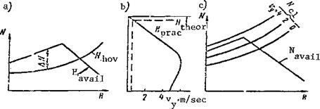
The vertical velocity at sea level amounts to 2-3 m/sec. The power available and engine power depend on the flight altitude, and with change of the altitude the vertical climb velocity will also change. The variation of the vertical climb velocity is determined by the altitude characteristics of the engine and is shown graphically (Figure 56a).

For a supercharged reciprocating engine the effective power will increase with increase of altitude from sea level to the critical altitude. The power required also increases. Therefore, the excess power may increase slightly or remain constant up to the critical altitude. After reaching the engine’s critical altitude the excess power decreases rapidly. Since the vertical velocity depends on the excess power, it will also decrease.

Using the graph of the variation of engine power and power required for /84 hovering as a function of altitude, we can use (25) to calculate V for various altitudes. On the basis of these calculations we can plot the vertical velocity as a function of altitude (Figure 56b), from which we see that the vertical velocity reaches its maximal value at the engine’s critical altitude, and then decreases.

The altitude at which the vertical climb velocity equals zero is called the helicopter’s static ceiling. The static ceiling is the highest altitude at which the helicopter can be hovered. At the static ceiling the excess power AN = 0.

However, since both AN and AV approach zero as the helicopter approaches the static ceiling, it is not possible to reach an altitude equal to the theoretical static ceiling. The "practical ceiling" concept has been intro­duced on this basis. The practical ceiling is the altitude at which the vertical climbing velocity equals 0.5 m/sec.

The static ceiling is defined in terms of rated engine power. A specific power required corresponds to each vertical velocity. Therefore, we can plot the power required for climb as a function of altitude for different vertical velocities (Figure 56c). From this graph we can find the vertical climb velocity at various altitudes for different power required. The altitude characteristic can be used to evaluate the possibility of climbing with a given vertical velocity.

Transition From Flight With Engine Operating to Flight. in the Main Rotor Autorotation Regime

Gliding in the autorotative regime is not an emergency flight mode ; rather it is a normal, stable flight mode which is often used even with a normally functioning, sound engine. Gliding in the autorotative regime is

used for working out basic piloting techniques or for rapid loss of altitude. However, in order to assure safety, a definite order and sequence of actions must be followed in transitioning from flight with the engine operating into the autorotative regime. What happens with the helicopter in the case of sudden engine stoppage or in case of rapid decrease of the engine rpm?

The main rotor continues to rotate momentarily, and the rpm does not change, since the freewheeling clutch automatically disengages the engine from the transmission. The rotor continues to turn by inertia, since it has definite angular momentum. The greater the mass or weight of the blades, the larger the moment of inertia, the longer time the rotation will continue by inertia. Therefore, heavy blades have an advantage in the autorotative regime.

Under the action of the reactive moment, the main rotor rpm decreases, and therefore the thrust decreases. If the engine fails in the hovering regime, then as a result of main rotor thrust reduction, the helicopter will transition to vertical descent. However, if the engine fails in horizontal flight, reduction of the thrust and lift will cause the helicopter to descend along an inclined trajectory. In both cases, the air flow will approach the main rotor from below.

The presence of the vertical velocity causes increase of the blade element angles of attack by the magnitude Да and deflection of the force vector AR forward, i. e., a driving torque appears; therefore, there is an increase of the rpm or at least no further reduction of the rpm. Moreover, along with reduction of the main rotor rpm, there is reduction of the centrifugal force of each blade, which leads to increase of the main rotor coning angle, i. e., simultaneous upward flapping of the blades. When the flapping angle increases, there is a reduction of blade pitch under the influence of the flapping compensator, i. e., there is an increase of the main rotor rpm.

Thus, we conclude that in the case of engine failure, there are objective factors which facilitate transition of the main rotor into the autorotative regime. But the pilot must not rely on these conditions and expect the rotor

itself to transition into autorotation. Therefore, in case of engine failure, /135 the pilot must immediately reduce main rotor pitch to the minimal value. To this end, the collective-throttle lever is lowered fully. The main rotor rpm increases, and the circumferential velocity of the blade elements increases.

This leads to reduction of the blade element angles of attack and aft deflection of the force AR. Therefore, the main rotor rpm will increase up to some limit, and then the constant rpm regime is established, i. e., the autorotation becomes steady. However, if the rpm is too high, the pitch must be increased somewhat. During flight with the engine not operating, the rpm should correspond to the engine rated power rpm. In this case, the rotor will develop the maximal thrust force, and the vertical rate of descent will be minimal.

Transition of the main rotor into the autorotative regime is facilitated

by the stabilizer mounted on the tail boom. The stabilizer incidence angle

changes with change of the main rotor pitch: when the pitch is reduced to

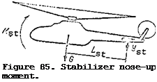
the minimal value, the stabilizer incidence angle becomes negative (Figure 85).

If at the time of transition into the autorotative regime the helicopter is

moving with a horizontal velocity, the negative lift force Y develops on

the stabilizer. The moment of this force M = Y L causes helicopter

st st st

nose-up pitch. The main rotor angle of attack becomes positive, and the air flow approaches the rotor from below. The angle Да of each blade element increases, and the rpm increases, i. e., the main rotor transitions into the autorotative regime.

So far, we have discussed the factors which accelerate or decelerate autorotation of the main rotor. We have devoted considerable attention to this factor, since main rotor rpm in autorotation is the primary index of flight safety. If the rpm is less than the minimal permissible value during autorotation, the rotor can come to a stop — which is a problem which cannot be rectified.

However, during transition into the autorotative regime, the pilot must devote some attention to factors other than main rotor rpm. The helicopter behavior at this time differs markedly from the behavior in steady-state flight:

First of all, there is a marked reduction of the main rotor reactive moment. As a result of this, the helicopter tends to turn to the right about the vertical axis. Moreover, if there is a horizontal velocity, there will be flapping motions of the blades, and this means that the main rotor coning axis will tilt to the right.

Подпись:As a result of the main rotor thrust force side component, the helicopter will bank and slip to the right.

Подпись: /136At the moment of transition into the autorotative regime, the pilot must prevent rotation of the helicopter about the vertical and longitudinal axes by reversing the tail rotor thrust force and deflecting the main rotor cone of rotation to the left. The tilt of the helicopter fuselage relative to the horizon depends on the flight speed. At low speed, the tilt reaches 10-15°, i. e., the nose of the helicopter is quite high. This cannot be permitted, as the helicopter tail rotor may come in contact with the ground, and tail rotor failure may occur.

In steady-state autorotation the main rotor blades develop a driving torque. Under the influence of this torque, the blades are rotated forward relative to the vertical hinge to a negative lag angle. During glide, the driving torque depends on the azimuth angle. Therefore, the lag angle will vary, i. e., during glide, the blades will oscillate about the vertical hinges.

Resultant Flow Velocity over Blade Element in the Hub Rotation Plane

It is well known that in the vertical flight regime each blade element is in a stream whose velocity is equal to the circumferential velocity of the element u = шг.

The situation is different in the forward flight regime. If the main /45

rotor angle of attack A = 0° , the resultant velocity with which the stream flows over the blade element depends on the element circumferential velocity, the

Подпись:flight speed, and the azimuth angle p. In this case the resultant velocity will not be equal to the geo­metric sum of the circumferential velocity and the flight velocity, since only the flow directed perpen­dicular to the blade longitudinal axis has an influence on the aero­dynamic forces of the element.

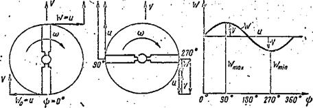
Therefore, we must take as the resultant blade element velocity in the forward flight regime the sum of the vectors of the circumferential velocity of the blade element and the projection of the flight velocity vector on the line of the circumferential velocity vector (Figure 31).

V/ = Vclnb. (16)

Consequently, for a constant flight speed and constant angular velocity the resultant velocity will vary as a function of the azimuth angle.

Let us examine the variation of the resultant velocity as a function of blade azimuth (Figure 32) .

V I/ У

Resultant Flow Velocity over Blade Element in the Hub Rotation Plane

Figure 32. Blade element resultant velocity as a function of azimuth.

It is not difficult to see that for ip = 0° and 180° the resultant velocity equals the circumferential velocity, since the projection of the flight velocity on the circumferential velocity vector equals zero (Figure 32a)

W0 = U+V sin 0° == U,

V/m = u + Vsin 180° = U.

For ф = 90° the resultant velocity is /46

V7fl0 = и + V sin 90° = U – f – V.

For ф = 270° the resultant velocity equals the difference of the veloci­ties (Figure 32b)

y270 — u-i-V sin 270° = 11- V.

If we use (16) to calculate the resultant velocity for several azimuths, we can plot the relation W = f(4>) (Figure 32c).

Figure 32 makes it possible to conclude that:

the maximal blade element velocity will occur at ip = 90°, the minimal will occur at ip = 270°; for ф = 0° and 180° the resultant velocities of a given element are equal to the circumferential velocity of this element. Consequently, the forward flight regime differs from the vertical flight regime in the vari­ation of the blade element velocity. In the vertical flight regime this velocity remains constant W = u and is independent of the azimuth. In this regime the "blade azimuth" concept has no meaning. In the forward flight regime the resultant blade element velocity in the hub rotation plane varies continuously.