Category Helicopter Test and Evaluation

Main rotor power

It is now possible to combine all these improvements into a single relationship for the power required by a single main rotor (including an estimate of the effect of tip losses on the induced power), for example:

1 f 1

Подпись: (2.17)Cp = L2XCT + — p3 — + p sCd(1 + 43p2) + Cpm + Cp,
CP — Cpj + Cppa r + CPpr + Cpm + CPs

where the subscripts represent: i – induced; par – parasite; pr – profile; m – Mach and s – stall.

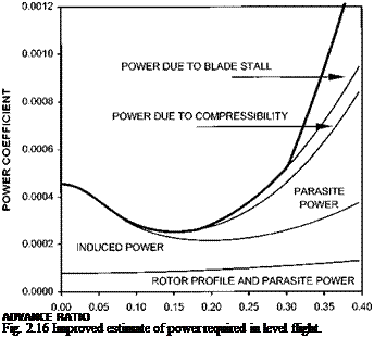
Подпись: ADVANCE RATIO Fig. 2.16 Improved estimate of power required in level flight.

Figure 2.16 shows a more realistic variation of power coefficient with advance ratio.

Note how the induced power rises at high forward speed as larger disk tilts and higher thrusts are required to balance the drag. Likewise, note the significance of compressibility and blade stall at high advance ratio. These two factors are often combined under a single term ‘tip effects’.

Blade stall and drag divergence

The high subsonic Mach numbers and high angles of attack experienced by rotor blades cause reductions in lifting performance (stall) and increases in drag (drag divergence). As both these effects cause an increase in the power required by a rotor they are typically included as additions to the power coefficients already determined. Although the variation of angle of attack and Mach number around the azimuth of a rotor in horizontal flight is complex these additional coefficients are calculated by assuming that drag divergence is most significant at ^ = 90° and blade stall at ^ = 270°. Estimation of the power increment due to compressibility (CPm) begins by determining the tip Mach number at ^ = 90° (M90). This Mach number is then compared with the

image18

Fig. 2.15 Variation of main rotor skew angle with forward speed.

drag divergence Mach number that is itself dependent on the local angle of attack (a9C)). Thus after Gessow and Crim [2.19]:

CPm = 40.012 *Md + 0.1(*Md )3 ]

where:

*Md = M90 – Md – 0.06

and, as an example, from Prouty [2.6] for NACA 0012:

Md = 0.726 – 2.45«90

The local angle of attack is found by combining collective pitch (0C), blade twist (9T), longitudinal cyclic pitch (B1) and an inflow angle obtained from the mean induced velocity (vi0) [2.4]:

X

a90 = 90 + 9T + B1 + "j

1 – h

The increment in power coefficient due to retreating blade stall (CPs) is handled by assuming that the stalled region is diamond-shaped and centred about ^ = 270°. Within this region the section profile drag coefficient is taken to increase by 0.08 (for a NACA 0012 section). Hence, from Castles and New [2.20]:

cPs = 4z (1 – h2 )(1- X) V1 – X 2

where Xs is the dimensionless radius beyond which blade stall is present. This radius can be found by setting the general equation for angle of attack along the radial at ^ = 270° equal to amax [2.4 and 2.21]:

X

^max = 00 + XS0T — B1 + TP

Xs — p

Although amax varies with Mach number it is often sufficiently accurate to use the angle of attack above which low speed separation occurs (12.5° for a NACA 0012 section [2.21]). A correction to CPs is included if an unstalled section at the retreating tip bounds the stalled region.

Non-uniform inflow

Although Glauert [2.11] provides a simple method of calculating the mean induced velocity for a rotor in horizontal flight he, along with others who have studied lifting

1 + * [r

Подпись: V = vi0 Подпись: cos ^ Подпись: (2.16)

rotors [2.15 and 2.16], appreciated that the induced velocity over a rotor is far from uniform. Consequently they proposed additional formulae designed to generate an upwash ahead of the rotor disk and a steadily increasing inflow along the rotor diameter similar to that seen along the chord of an aerofoil. The formula proposed by Glauert is sufficiently accurate for our purposes:

Note that if К is set to a value greater than 1 (typically 1.2 [2.17]) an upwash results and a linear fore/aft variation in induced velocity is predicted. Lateral variations, although present in reality, have been ignored at this level of simplification. The term vi0 represents the mean induced velocity found using Equation (2.12). Before determining the effect of non-uniform induced velocity on the induced power required in forward flight, it is necessary to consider the skew angle of the rotor wake. This skew angle (%) is measured from the vertical and indicates the direction taken by the ultimate wake from the rotor disk. Once again several formulae exist to predict % [2.6, 2.15 and 2.18]. Although some include wake contraction, the simplest assume a cylindrical wake. The following relationship from Prouty [2.6] is most often quoted:

1 = Vo

tan % V

Note that since a cylindrical wake is assumed, the induced velocity at the rotor hub is used rather than the ultimate wake value of 2vi0. Now from Equation (2.12):

1 = гг ИГ

tan % J 2 + V 4 + V4

Figure 2.15 shows a typical variation in skew angle with horizontal speed. As with tip losses in axial flight it can be shown [2.17] that the extra induced power required by non-uniform inflow can be taken into account by applying a factor к to the estimate of induced power based on a uniform inflow. Therefore, for small disk tilt:

Pi = кРі0 = KTvi = KWvi

Estimates for к vary from 1.17 [2.17] to 1.2 [2.10].

Reversed flow

It has been shown that the chordwise velocity of a blade element is given by:

U = )r + V sin ^

On the retreating side the components of rotational velocity and horizontal velocity are subtractive and a region of reversed flow will exist. It can be shown that this region is circular in nature with a diameter equal to pR. At low forward speed this region is usually of little consequence as the aerodynamic section of the blade does not begin until some distance from the hub (0.25R is typical). Since the flow in the reversed flow region is from trailing edge to leading edge it has the effect of pushing the rotor around the mast thereby extracting power from the airflow. Although the amount of negative power is usually quite small and often ignored, it may, however, be approxi­mated by an 8% reduction in the forward speed dependent component of rotor power

[1.4] , thus, for example, reducing k from 4.65 to 4.30. Hence the power required in forward flight may be estimated using:

Cp=2 (a ) + ^Ct +1 ^ + 4.3^2)

Figure 2.14 shows the variation of angle of attack across a rotor disk at a high advance ratio (p = 0.34). Note that the reversed flow region is clearly delineated.

HORIZONTAL FLIGHT: IMPROVED THEORETICAL ESTIMATES

When blade element theory was applied to axial flight, it proved useful in identifying the profile power required. Unfortunately, the theory failed to capture the complexities of the real situation requiring both theoretical and empirical adjustments. Likewise the relationships so far developed for horizontal flight can be modified to account for:

• Spanwise flow;

• Reversed flow;

• Non-uniform inflow;

• Blade stall and drag divergence.

2.9.1 Spanwise flow

The method of accounting for the hub force generated by the asymmetry of drag around the azimuth (introducing d. D sin ^) fails to consider the flow of air along the blade, the so-called spanwise flow. This omission becomes clear if one considers a blade aligned with the longitudinal axis of the helicopter and situated over its nose. Here the freestream flow is along the blade from tip to root. Although the drag associated with this flow will generate a hub force the sin ^ term fails to account for it since sin 180° = 0. The practice of replacing the factor 3 with a larger empirical value k in Equation (2.15) rectifies this omission. Studies have suggested that appro­priate values lie between 4.5 and 4.7 [2.13 and 2.14].

image17

Fig. 2.14 Variation of angle of attack across rotor disk.

Rotor profile power

From Fig. 2.13 the elemental rotor profile power is given by:

SP = ) 82 = )r 8D = )r1 p()r + Vsin ^)2c Sr CD

The profile power can be obtained by multiplying SP by the number of blades, b, and integrating both along the radius and around the azimuth:

1 P 1

Ppr = 2^b I I 2P )rCD()r + Vsin^)2cdrd^

Подпись: J0 J0 Note that 1/2 л is introduced because the average power required around the azimuth is needed. Now:

1 1 C2n P

Ppr = — pbc) 2 CD I I r()2r2 + 2 Vr sin ^ + V2 sin2 ^)dr d^

Jo Jo

Thus from Layton [2.4]:

PPr = 8 pbcVT RCD(1 + P) (2.13)

Comparison with Equation (2.6) shows that the profile power in horizontal flight can be found by calculating the profile power required in the hover and scaling it by a factor equal to (1 + p).

1.7.2 Rotor parasite power

Likewise from Fig. 2.13 the elemental rotor parasite power is given by:

SP = VSH = VSD sin t = V2 p()r + Vsin tP Sr CD sin t Therefore:

Ppar = 4 pbcV3 RCDp2 (2.14)

1.7.3 Power required for horizontal flight

We are now in a position to determine the power required for horizontal flight using Equations (2.11), (2.13) and (2.14). It is customary to add the contribution from rotor parasite power to the rotor profile power rather than the fuselage parasite power. Thus:

P = T(Vsin у + vi) +1 pbcRVf CD(1 + p2) +1 pbcRVT CDp2 8 4

P = 2 p V3f + Tvi + 8 pbcRVT CD(1 + 3p2) and in coefficient terms:

Cp = 1P3 f + XCT +1 "CD(1 + 3p2) (2.15)

Equation (2.15) is another important result since it suggests that for a helicopter (fixed f /A) at a given weight (fixed CT) the power coefficient will depend solely on the advance ratio (p). Also if the advance ratio is fixed and the rotor profile drag coefficient is constant then the power required to drive the rotor will vary as ) so that CP remains unchanged. This relationship gives us a mechanism for assessing the effect of changes in rotor drag on the level flight performance of a helicopter.

HORIZONTAL FLIGHT: BLADE ELEMENT THEORY

Although momentum theory can be used with some success to determine the power required by a helicopter in horizontal flight it does not gives us a complete analysis of the situation. As with axial flight we have to adopt a blade element approach if we are to understand the power requirements more fully. The elemental thrust, torque and power can be written as:

ST = SL cos — SD sin ^

82 = (SL sin ^ + SD cos ^)r

SP = (SL sin ^ + SD cos ^) )r

On integrating the torque equation, it was found to contain elements that matched those obtained using momentum theory. These elements can be traced to the presence of SL sin ^ in the elemental torque equation. It is therefore possible to simplify the mathematics associated with using blade element theory by only considering the drag component. The estimate of power required using this method is then added to that

the hub. By integrating the drag force acting normal to the blade element a relationship for the profile power is obtained. Unfortunately, this is not the complete picture. Although the power required to drive the rotor around the hub has been found, in the face of a horizontal airstream (V), it has not accounted for the power required to drive the rotor system forward: the rotor parasite power. This additional power arises because there will be a hub force acting rearwards which must be matched by a component of the rotor thrust. The hub force appears because there is an asymmetry of drag acting on opposing blades. When a blade reaches the advancing side, it will see increased drag, a component of which will act rearwards. An opposing blade will see reduced drag as it enters the retreating side. Although a component of the drag on the retreating side acts forwards, it will be less than on the advancing side and a net rearward hub force will result.

Estimating the induced velocity

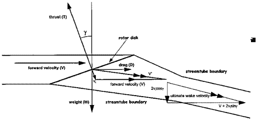
If a helicopter in horizontal flight at speed V (see Fig. 2.10) is considered then in order to sustain level flight the rotor disk must be tilted forward. This is so that the thrust vector, T, can provide both the forward propulsive force (Tsin y) and support the weight of the helicopter (Tcos y). Now the rotor will induce a flow through itself at right angles to its plane of rotation. The combination of the forward speed, V, and this induced velocity, v1, is the oblique flow across the disk, V’. From Equation (2.10):

T

v =———

1 2pAV’

and from Fig. 2.10:

V’ = V(V + V1 sin y)? + (v1 cos у)? = V(V? + 2Vv1 sin yv?

Подпись: Tcos у = W Tsin у = D Estimating the induced velocity

Also:

Estimating the induced velocity Estimating the induced velocity

Thus:

or:

Подпись:___________ 1__________

cos у V V? + 2 Vv1 sin у + v?

1

Подпись: V, = -image14
‘VV2 + v2

and using the quadratic solution of V4 with a positive root:

_ , V 2 V4

v=-l _t+vt +1

which can be approximated at higher forwards speeds, when V is much greater than V,, by:

W

v =—–

1 2pAV

Figure 2.11 shows the predicted variation of induced velocity ratio with forward velocity ratio. At speeds in excess of twice the induced velocity in the hover the simple approximation can be used. (For the example helicopter this equates to a forward speed of around 30 m/s or 60 KTAS).

1.7.1 Estimating the ideal power:

From Fig. 2.10 it can be seen that by using Equation (2.11) it is possible to write the ideal power in coefficient terms:

Подпись: pAVT Подпись: pAVT Подпись: pAV

PDEAL T (V sin у + V,) DV + Tv, 13/ f

image15

where f = SCD = drag area (area of flat plate that produces equivalent drag to helicopter body) and p = advance ratio (V/VT). Thus the ideal power coefficient comprises two components: one proportional to the cube of the advance ratio – the parasite power; and one proportional to the inflow ratio (X) – the induced power. Figure 2.12 shows the variation of ideal power coefficient for the example helicopter, note the presence of the familiar ‘power bucket’.

Elliptically loaded wing analogy

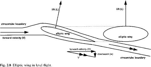
The analogy with an elliptically loaded wing, suggested by Glauert, provides us with a relationship for thrust. From Fig. 2.8 it can be seen that a lifting wing imparts a downwash velocity, w, on the flow as it passes over the aerofoil. If the wing is elliptically loaded then its effect on the air will be the same as a rotor with uniform inflow, (Fig. 2.9). Induced power, Pi, equals Tvi; since the rotor is assumed to act like a wing, Pi is considered to be the power required in overcoming the induced drag. Thus:

1

P = Tvi = V Di = 2 P^(V @ )3CDi

image12

image13

Fig. 2.9 Momentum disk in level flight.

Elliptically loaded wing analogy Подпись: T 2 2pAV'

But for an elliptically loaded wing (after McCormick [2.12]):

and so:

T = 2pAV’v1 (2.10)

Equation (2.10) provides the means to calculate the induced velocity in horizontal flight since T and V’ can be estimated from Fig. 2.8 and by considering the forces on the helicopter. The power required to drive the helicopter (PIDEAL) can be determined, as before, from the product of the thrust and the axial component of the relative speed of flow through the disk. Thus, the ideal power is given by:

pIDEAL=T (V sin у + v) (2.11)

The windmill-brake state

At rates of descent in excess of vih the vortex ring rises above the disk and the rotor is said to be operating in the turbulent windmill-brake state. Although less problematic it is still a working state for which momentum theory is inappropriate. For still higher rates of descent (the windmill-brake state) momentum flow is restored with the rotor extracting sufficient energy from the rising air to maintain the rotor speed and generate thrust. In theory, the rotor can operate satisfactorily up to very high rates of descent in the windmill-brake state. A rotor is said to be operating in an ideal autorotative state if there is no mean flow through the rotor. Consequently the induced power is zero and the helicopter is able to make a controlled descent with potential energy being used to meet the power requirements of the rotorcraft. Theoretically, autorotation is achieved in vertical flight at a rate of descent equal to 1.8 vih. In practice however the requirement to overcome the profile drag of the rotor blades changes the rate of descent to 1.7 vih.

1.7 HORIZONTAL FLIGHT: MOMENTUM THEORY

It has already been stated that the momentum theory is inaccurate for low rates of descent. It is also true that these inaccuracies will persist if the theory is applied at low forward speed. Glauert [2.11] proposed that if the forward speed is large compared with the induced velocity then the momentum theory could be applied successfully. He also suggested that it was possible to make a direct analogy between a rotor and an elliptically loaded wing.