Category Model Aircraft Aerodynamics

MO DESIGN OF CAMBER FLAPS

Піе design of variable camber wings is not easy. The air must not be forced to flow round sharp comers or meet severe adverse pressure gradients, since the boundary layer can easily separate and cause very high drag. Flap hinge lines must be carefully sealed to prevent leakages from high to low pressure sides of the wing, or from inside the wing to the jutside. Ideally, the whole aerofoil should be designed for use with flaps. The flap should

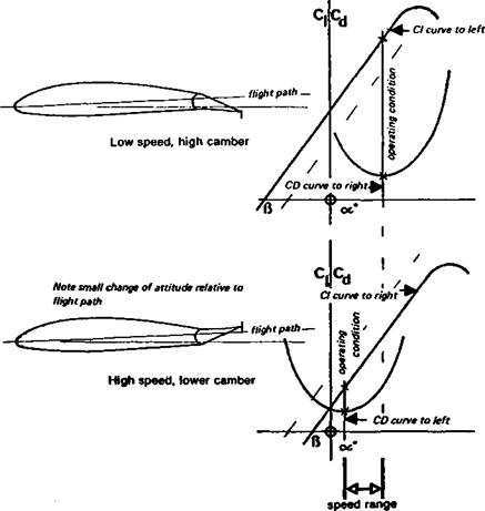
Fig. 7.9 Plain flaps used to widen the speed range of a sailplane

extend across the whole span, not terminating at the ends of the ailerons. The ailerons should droop or rise together with the flaps. This is particularly important at low speeds, since the sharp change in angle of attack caused where the flap ends amounts to giving the wing a very pronounced and abrupt washout, with bad effects on the carefully designed elliptic lift distribution, and hence high induced drag. The flaps may also be used by themselves as landing aids. Some successful multi task sailplanes use ailerons and flaps opposed for landing, both the ailerons being deflected up as the flaps go down. This creates both high profile drag and vortex drag where the flap and aileron meet at very different angles. Advances in electronic coupling of controls has greatly eased the problem of engineering involved in such a system. It is commonly found that, with this arrangement, some aileron control is lost at low speed.

A true variable camber wing, with a flexible skin on one or both surfaces and internal levers to increase or decrease curvature, is aerodynamically superior to a wing with flaps. Some full-sized sailplanes have adopted such devices (e. g. the HKS series, and the Polish Jantar). With modem plastic materials it is quite feasible for a model to have a flexible surface on one side, so that the simple flap joint is fully sealed and smoothly curved, rather than sharply kinked (Fig. 7.11).

VARIABLE CAMBER

Models which are required to perform efficiently over a wide range of airspeeds present great difficulties. This applies particularly to cross-country and multi-task radio controlled sailplanes. When soaring, they must be trimmed for a high Cl and for low drag should have a strongly cambered wing. At speed, a low-camber or even a symmetrical profile is required. As noted previously, a high aspect ratio is the chief means of achieving a low sinking speed, but profile drag is not negligible. At speed, profile drag is most important. No one value of camber can be ideal for all flight conditions. If a simple wing is used, the camber should be on the low side, for high speed, relying on high a. r. for the soaring flight The aerofoils used should be chosen to give low drag coefficients over wide range of angles of attack. Preferably a laminar flow aerofoil with a wide low-drag-range or ‘bucket’ should be used (Chapter 9). Even better, such a profile combined with a variable camber wing allows the drag to be reduced in all conditions. Plain flaps widen the speed range as shown in Fig. 7.9. Most modem full-sized sailplanes combine flaps with wide – drag-range aerofoils. In thermals or hill lift, the flaps are depressed, shifting the drag curve to the right and the lift curve left Between upcurrents, to achieve good penetration, the flaps are raised, usually beyond the neutral position, to shift the drag and lift curves in the opposite directions. The pilot constantly adjusts the flaps as the airspeed is changed. With a well-balanced design, the attitude of the fuselage to the airflow hardly changes, in fact one well-known high performance sailplane could be trimmed by means of a spirit level – at any speed with appropriate flap setting, the attitude remained exactly the same. The advantage of this was that the fuselage presented the same aspect to the airflow at all speeds, and thus parasite drag was a minimum for the particular shape used. (See also 11.4). With less refined design, the fuselage changes its angle of attack somewhat, and produces more drag, with different flap settings.

For powered duration models the advantage of variable camber is also clear. The low 3l required for the high speed climb is achievable by trimming the tailplane, to hold the ring at a low angle of attack, but with a high camber, this produces much too much profile lrag. It is better to reduce the wing camber for the climb, cutting profile drag at speed. Піеп for the glide, the low drag and high Cl required may be achieved by increasing :amber, lowering wing flaps after the motor cuts. Re-trimming the tail will also probably ye necessary.

CAMBER AND DRAG

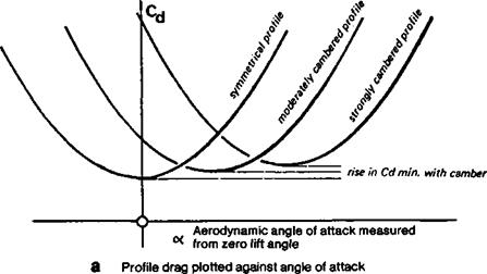
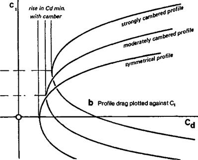
For most of the time the landing condition is not particularly significant for models. The reason that slow flying models should have well cambered profiles, and fast models less cambered ones, is entirely a matter of drag reduction. The influence of camber on drag of an aerofoil is shown in Figure 7.7. Compared with symmetrical wings, the cambered surface has a slightly higher minimum profile drag, but far more significant is the movement of the drag curve as the camber increases. The angle of attack in Figure 7.7a is the aerodynamic angle, measured from the absolute zero. In some earlier wind tunnel testing, the drag graph was plotted against angle of attack measured geometrically. The rightward shift of the curve was to some extent concealed, since it was easy to overlook the /е/1-ward shift of the lift curve with camber. In modem practice, the drag curve is always plotted against ci directly (Fig. 7.7b) and the true relationship is then clear. (The angle of attack has to be found by cross plotting to the ci curve.) In practice the modeller seldom knows at what angle of attack the wing operates, since the model’s attitude changes frequently. Downwash in any case induces a different angle from the simple geometric expectation, but the wing Cl is controlled by trimming. It is of utmost importance that the camber should be correctly chosen to give minimum drag at the particular Cl at which the model is flying. This is particularly vital for high speed models

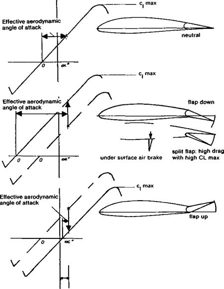
Fig. 7.6 Hinged control surfaces

Geometrically the angle of attack is always measured from the chord or other reference line with zero control deflection. The aerodynamic effects are as shown when controls are deflected.
Подпись: rise in с/ for min Cd as camber increases

where profile drag is such a large item in the drag budget; it is less important, though still significant, for slow flying models.

Some pylon racers have been built with the wrong camber As Figure 7.7 shows, there is one value of q at which profile drag is a minimum for each value of camber. If a symmetrical wing is trimmed to fly at a positive angle of attack, as it must be for flight in equilibrium, it will operate at some point on the drag curve above the minimum. On the other hand, if a cambered profile is trimmed at too low a q, it too will produce too much drag.

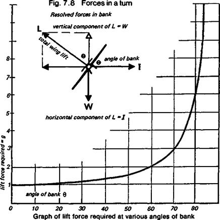
With the help of a little arithmetic it is possible to determine the best camber for any speed model, if its actual speed, or the speed hoped for in the design stages, is known. This is explained in Appendix 1. At maximum speed in level flight very little camber is required, with a light model, but racing models spend comparatively little of their flying time in equilibrium, they not only fly straight and level, but have to bank round the pylons. This, as shown in Figure 7.8, increases the ci at which the profile operates, to generate the extra lift force to counteract inertia in the turn. How much extra force is needed depends entirely on the angle of bank; a bank angle of 60 degrees doubles the effective lift required, a further eleven or twelve degrees triples the load, and banking angles of 80 degrees or more send the ‘g’ forces rocketing. In such steep turns the wing is forced to a higher angle of attack, and with the thin slightly cambered profiles commonly used, this may cause a considerable increase in drag or even a stall The extra drag slows the model down, reducing the average speed for the lap in any case. It may be much more significant than that The reduction of V in the lift formula means that the Cl must go still higher. With a thin, slightly cambered wing, this too can produce a stall and the race ends immediately for that model. The model needs either a wing which produces low drag over a range of ci values, such as one of the laminar flow aerofoils discussed in Chapter 9, or it needs a variable camber wing, i. e. flaps which can be lowered slightly at the turns; not so much to increase Cl, but to shift the drag curve to give minimum profile drag at the higher angle of attack in the turn.

For duration models and gliders which are trimmed to fly at Cl’VCd maximum, it is necessary to reduce profile drag as far as possible by moving the drag curve to a high ci position, accomplished by cambering more. This also raises the ci maximum, enabling the model to be trimmed for slow flight The ideal camber is harder to determine than for a speed model, since the calculation method requires detailed wind tunnel test results for the profile used, and these are rarely available. Given such figures, like those presented in Appendix 2, the value of Cl1 5/Cd, duly corrected for the aspect ratio and with allowance for parasite drag, may be calculated by arithmetical methods and plotted on a graph to find the best operating Cl and check the camber again. The model may then be trimmed to fly at the airspeed appropriate to the Cl – Some examples of the type of calculation required are given in Appendix 2.

FLAPS AND CONTROLS

Highly cambered aerofoils are often referred to as ‘high lift’ sections. It is true, as Figure 7.4 shows, that the highly cambered section has a higher ci max. This is familiar enough and is the reason why full-sized aircraft and some models have landing flaps. The point is not that such surfaces, or their equivalent, highly cambered wings, develop more lift force. In equilibrium, lift equals weight. The wing with flap down has to support only the same aircraft weight, but, operating at a high Cl, it can do this work at a lower airspeed. Hence the value of flaps for landing and take off. Figure 7.6 shows the effect of moving any hinged surface such as an aileron, rudder or elevator, or a wing flap of the plain variety, to different angles. As the flap goes down, the whole ci curve moves to the left on the graph, and upwards. At the same time, if the attitude of the aircraft to the flight path is not altered, the effective angle of attack increases because the chord line of die wing is in a new position. On raising the flap, the converse happens. The effect of such hinged surface movements is a combination of increased camber and increased angle of attack, or vice versa. Split flaps have similar camber-changing effects, but have the advantage for landing of also creating high profile drag. This decreases the L/D ratio and steepens the glide path on the approach, helping the pilot to judge his touch down position accurately. Such flaps have value on models required to carry out precision landings. Under-surface airbrakes, mounted at about 50% of the chord, also change the wing camber and increase ci max. slightiy, with high drag. This type of brake has been used in some full-sized sailplanes but is vulnerable to ground damage. All camber-changing devices change the pitching moment of the aerofoil, as discussed more fully in the last section of this chapter.

STALL CONTROL BY CAMBER CHANGES

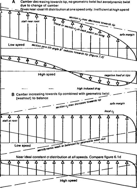
By varying the camber along the span, the stalling characteristics may be controlled. If the camber is reduced towards the tips, with no geometric twist (i. e. the true chord line of each rib is at the same angle to the building board or datum line), the wing will have an aerodynamic washout because the aerodynamic zero angle of attack at each point will differ. Assuming a nearly elliptical planform, the wing roots, because of the greater camber there, will reach their stalling angle before the tips. This is good in the sense that it prevents tip stalling. At high speeds, however, when the roots are still lifting, the tips will already be close to their aerodynamic zero. The lift distribution will not be elliptical, and at some speed the tips will begin to bend downwards like a wing with marked geometrical washout (Fig. 7.5). To restore elliptical lift distribution, the tips should really be twisted the other way (wash-in), which will unfortunately cause tip stalling because the less – cambered profile has a lower ci maximum. Many models have been built with reduced camber at the tips plus a few degrees of washout. This combines both aerodynamic and geometric washout; the total effect may be as much as six or seven degrees of aerodynamic twist The tip stall is controlled, but the efficiency suffers.

If, instead of camber decreasing at the tips, it is increased, or decreased at the roots, the tips will tend to stall first which is highly undesirable. However, if the aerodynamic twist or ‘wash-in’ caused by the increased tip camber is counteracted by an equal geometric twist or washout in the opposite direction, the result is excellent If, for example, the differ­ence in absolute zero of the aerofoil at the wing root and that at the tip is two degrees, with the more cambered form at the tip the geometric twist should be two degrees washout or, to be on the safe side, a little more. The whole wing then reaches its aerodynamic zero at the

same angle, and the ci from tip to root is nearly constant The lift load thus approaches as closely as possible to the ideal (assuming the planform of the wing is a good approximation to an ellipse). There is no tip stall, because the more cambered profile has a higher ci max., and, measured from the aerodynamic zero, stalls later. Hence the root reaches the stalling angle first The wing is efficient over a wide range of speeds. This technique is widely used by designers of full-sized sailplanes and may be applied to models in exactly the same way. In design it is essential to know the zero-lift angle for the’ profiles used. This may be obtained from wind tunnel results if available. In some cases the figures are given with the aerofoil ordinates (as with the Eppler profiles whose ordinates are given in Appendix 3). Wind tunnel results do not always confirm the computed figures. On the building board it is of course very important to lay out such a

Fig. 7.5 Camber, aerodynamic and geometric twist

«

wing accurately. The ribs may be cut by the sandwich method between templates of the appropriate aerofoils at tip and root, or the section may be constant to the semi – or two – thirds span position and changed progressively from there to the tip. Cutting foam plastic wings is equally straightforward. On assembly, careful work should ensure that the angle of each rib is correct relative to its designed chord line. A casual chocking up of the trailing edge to some angle or other is not good enough.

THE AERODYNAMIC ZERO

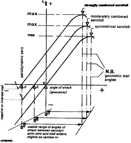
If a symmetrical aerofoil is at zero angle of attack, it yields no lift, whereas a cambered one will lift when its chord line, i. e. the straight line from extreme leading edge to trailing edge, is parallel to the general airflow. But a cambered profile can be moved to some negative angle at which it, too, will produce no lift This angle is most important and is known as the aerodynamic or absolute zero angle of attack for a particular aerofoil. The more cambered the mean line, the more negative, relative to die chord line, will the absolute zero angle be. On graphs of lift against drag for aerofoils in one family the more cambered profiles’ lift curves are always to the left, i. e. towards the negative side, as shown in Figure 7.4. However, the slope of the lift curve on such graphs, for one aerofoil family, is the same in each case. This remains true so long as the camber is not so great that streamlining breaks down. As shown, the more cambered aerofoil of a family tends to reach a higher value of Cl before stalling than the less cambered, but the geometric angle of attack at which the stall occurs is earlier. Only if the angle of attack is measured from the absolute zero in each case does the more cambered profile stall later. This suggests some important practical points for the design and construction of model wings.

DESIGNING A NEW PROFILE

Knowing the mean line of any aerofoil, it is possible to experiment with a family of profiles based on it Different thickness forms may be fitted to it, and new aerofoils created in this way. Alternatively, a preferred thickness form may be fitted to various differing mean lines to try the effects of increasing or decreasing camber, moving the point of maximum camber forward or aft, and so on. Methods of doing these things are outlined in Appendix 3.

7.3 ERRORS AMONG MODELLERS

Modellers sometimes have mistaken ideas about camber. For example, aerofoils such as the well-known Clark Y, with flat undersides may be more cambered than some thinner sections which have concave undersides. In the same way, changing the thickness form of a profile does not change its camber – the NACA 4415 and 4409 are cambered both by 4%, but while one appears ‘undercambered’ the other is convex on both surfaces. For these reasons, the widespread habit of classifying aerofoil sections as ‘undercambered’, ‘flat bottomed’ and even ‘semi-symmetrical’, is very misleading and should be abandoned. The so-called semi-symmetrical profile is a cambered section and the camber may vary greatly from one such aerofoil to another, depending on the shape of the camber line itself in combination with the thickness form. Even perfectly symmmetrical sections differ considerably in flight because of their various kinds of thickness distribution. From the table of ordinates used to plot an aerofoil, the camber can be found by arithmetic, or from an accurate drawing it may be found graphically. (See Appendix 1). It is seldom possible to judge it by eye. It is also undesirable to modify camber arbitrarily. Some modellers, in the hope of obtaining more lift without increasing drag, ‘droop’ the trailing edge of their aerofoils. This introduces a kink in the mean line with effects usually bad. It would be better to choose a new properly designed mean line with an increased camber. In a similar fashion, either by design or by various tricks and dodges on the building board, modellers sometimes ‘reflex’ the trailing edge of a wing near the tips, intending to give a’ desirable ‘washout’. The effect in many cases is the opposite: a reflexed profile tends to stall sooner, rather than later, than an ordinary one of similar leading edge shape. The purpose of the reflex camber line is to reduce the pitching moment of the aerofoil, not to delay stalling (Fig. 7.3b). Another common term, referring to the leading edge of the

Fig. 7.2 NACA camber lines. Scale up or down to required maximum camber

а МСЯ fel.0 MOM LINE


Ь NRCR №0.» (CM LUC


c nrcr ни hern Luc


d NRCR ffcO. O HERN LUC


Fig. 7.3


a М3) 210 MEM LINE a IOERL 0.3


b REFLEX HERN LUC FOR ZERO FtTCHINB ROKNT. SORLE TO REQUIRED CRROER


Fig. 7.2 Mean line ordinates.

To obtain a mean line of a desired maximum camber, muliply each YU figure in the table by an appropriate factor.

abed

NACA A =

1.0 Ml:AN LINE

NACA A =

0.9 MEAN LINK

NACA A =

0.5 MEAN LINE

NACA A =

0.0 MEAN LINE

NACA 210 MEAN LINE

REFLEX MEAN LINE

CHORD

ORDINATE

CHORD

ORDINATE

CHORD

ORDINATE

CHORD

UPPER

CHORD

ORDINATE

CHORD

ORDINATE

STATION

STATION

STATION

STATION

SURFACE

STATION

STATION

XU

YU

XU

YU

XU

YU

XU

YU

XU

YU

XU

YU

0.000

0.000

0.000

0.000

0.000

0.000

0.000

0.000

0.000

0.000

0.000

0.000

.500

.250

.500

.269

.500

.345

.500

.460

1.250

.596

5.000

3.240

.750

.350

.750

.379

.750

.485

.750

.641

2.500

.928

10.000

5.770

1.250

.535

1.250

.577

1.250

.735

1.250

.964

5.000

1.114

15.000

7.650

2;500

.930

2.500

1.008

2.500

1.295

2.500

1.641

7.500

1.087

20.000

8.940

5.000

1.580

5.000

1.720

5.000

2.205

5.000

2.693

10.000

1.058

25.000

9.700

7.500

2.120

7.500

2.316

7.500

2.970

7.500

3.507

15.000

.999

30.000

9.990

10.000

2.585

10.000

2.835

10.000

3.630

10.000

4.161

20.000

.940

35.000

9.880

15.000

3.365

15.000

3.707

15.000

4.740

15.000

5.124

25.000

.881

40.000

9.430

20.000

3.980

20.000

4.410

20.000

5.620

20.000

5.747

30.000

.823

45.000

8.700

25.000

4.475

25.000

4.980

25.000

6.310

25.000

6.114

40.000

.705

50.000

7.760

30.000

4.860

30.000

5.435

30.000

6.840

30.000

6.277

50.000

.588

55.000

6.660

35.000

5.150

35.000

5.787

35.000

7.215

35.000

6.273

60.000

.470

60.000

5.460

40.000

5.355

40.000

6.045

40.000

7.430

40.000

6.130

70.000

.353

65.000

4.240

45.000

5.475

45.000

6.212

45.000

7.490

45.000

5.871

80.000

.235

70.000

3.040

50.000

5.515

50.000

6.290

50.000

7.350

50.000

5.516

90.000

.118

75.000

1.940

55.000

5.475

55.000

6.279

55.000

6.965

55.000

5.081

95.000

.059

80.000

0.990

60.000

5.355

60.000

6.178

60.000

6.405

60.000

4.581

100.000

0.000

85.000

0.260

65.000

5.150

65.000

5.981

65.000

5.725

65.000

4.032

90.000

-0.190

70.000

4.860

70.000

5.681

70.000

4.955

70.000

3.455

95.000

-0.300

75.000

4.475

75.000

5.265

75.000

4.130

75.000

2.836

100.000

0.000

80.000

3.980

80.000

4.714

80.000

3.265

80.000

2.217

85.000

3.365

85.000

3.987

85.000

2.395

85.000

1.604

90.000

2.585

90.000

2.984

90.000

1.535

90.000

1.013

95.000

1.580

95.000

1.503

95.000

.720

95.000

.467

100.000

0.000

100.000

0.000

100.000

0.000

100.000

0.000

EXAMPLE The A = 1.0 camber line reaches its maximum 50% chord, where the YU ordinate is 5.515 (5.515%) To reduce this to a 2% camber line, multiply all the YU figures by 2 – 0 3626

5.515

(Use an electronic calculator). Thus the new ordinates will read 0.0,0.0907,0.1269,0.1940 etc.

aerofoil, is ‘Phillips entry’. A profile with Phillips entry is one which has a modified camber line over the front 20-30% of the section, reducing the camber in this region. The camber of the profile should be considered as a whole and it is not good practice to modify a part of the aerofoil without considering the shape of the mean line from leading edge to trailing edge.

As will become apparent in what follows, to vary the camber of a wing towards the tips is an extremely usefiil design technique, enabling tip stalling to be prevented without any bad effects on performance. The technique, however, requires care.

AEROFOIL GEOMETRY AND FAMILIES

In designing aerofoils it is usual to consider the effects of camber and thickness form separately. This is justifiable only up to a point. The detailed airflow over the wing is affected equally by both camber and thickness, so both need to be considered simultaneously. It is useful, however, to begin with camber as an introduction to aerofoil theory and practice. In later chapters the complicating effects of the thickness form of the profile will be considered.

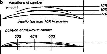
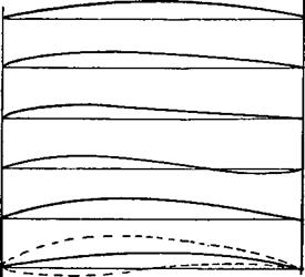
Any aerofoil may be considered as a basic ‘thickness form’ which has been bent round or fitted to a curved camber or mean line (Fig. 7.1). Profiles may be classed in families. A given basic thickness form may be fitted to a whole series of different camber lines, some curved more than others, some with the curvature concentrated towards the leading edge, some with it mostly towards the trailing edge, and so on. For example, a simple flat plate has a small thickness, has a leading edge shape – perhaps square, pointed or rounded, and a trailing edge form. It may be cambered in any way to create a family of aerofoils. The mean line might be a simple arc of a circle, or it might be a more complex form derived mathematically. When aerofoil ordinates are published the camber is sometimes stated in terms of percentage of the wing chord, and possibly the position of the maximum camber point is also given. Thus, aerofoils of the N. A.C. A.[1] series contain this information in their designations. When four digits appear after the letters NACA, the first digit refers to the camber amount, the second gives the chordwise location of die point of maximum camber. The last two figures give the thickness of the profile. All these are expressed in percentages of the chord. Thus, the NACA 6409 profile has 6% camber with die highest point of the mean line at 40% of the chord, measured from the leading edge, and the thickness is 09%. The 4412 profile has 4% camber at 40%, and is 12% thick. In the more modem NACA aerofoils of the ‘six digit’ series, the information about camber is given in a different form. The fourth figure in this series gives the lift coefficient, ci, for which the profile has been designed. The larger this figure, in general, the more cambered the profile, so for example the NACA 633615 and 633215 have ‘design lift coefficients’ of.6 and.2 respectively.[2] The last two figures give the thickness percentage as before. In some cases, following the six digits, a further statement appears, such as a = 0.5. This means that a certain type of cambered mean line (see Figure 7.2) has been used. Where this statement does not appear, the NAC A a = 1 mean line has been used. Other aerofoil systems adopt other methods of nomenclature which may include details of camber (see Appendix 3). The precise form of the mean line may differ from profile family to profile family. It is very rare to find a simple circular arc. Usually the curve is designed to serve a particular purpose. For example the NACA four digit profiles have mean lines which are made up of two parabolic curve segments joining tangentially at the point of maximum camber. The ‘five digit’ series (e. g. NACA 23012) have mean lines with the high point unusually far forward, designed to yield high maximum lift coefficients (Fig. 7.3a). It is more usual now to design mean lines to give a desired choidwise load distribution. The most commonly employed of these is the NACA a = 1 mean line (see Fig. 7.2a), which gives an even chord load distribution. The advantage of this is that each part of the profile is contributing its appropriate share of the lift, and hence, for any given value of ci, the least possible camber is required. This means less profile drag, other things being equal. However, there may be good reasons sometimes for using other forms of mean line, to reduce wing-twisting and pitching loads, for example, or, when aerofoils are designed for laminar flow, to help control the detailed pressure distribution.

Aerofoil sections: і. Camber

7.1 THE SIGNIFICANCE OF THE AEROFOIL SECTION

Quite often modellers draw out their own aerofoils freehand or with the aid of the simplest drawing instruments. It has even been said that a successful model wing has been designed by drawing round the edge of a favourite bootsole to produce nicely curved lines for the upper and lower surfaces of the profile. Such apparently casual methods can yield good results if informed by a good deal of experienced judgement The aerofoils produced in these ways are very orthodox. They resemble forms that have been in widespread use for many years, and these prototypes were originally designed under sound theoretical principles by aerodynamicists. The modeller who is content always to do what was done before will usually produce a model which flies very much like the one before but it will not represent any advance in development. An even safer procedure is to copy slavishly the wing of a well-known successful model of identical type, and again, good results may be expected. Unfortunately this procedure leads to stagnation as modellers follow current fashions without much fundamental re-thinking.

The effects of a moderately bad aerofoil on a s/ow-flying high Cl model, as Figure

4.10 suggests, may not be very serious because profile drag is a comparatively small proportion of the total. By skilful tactics and experienced judgement about when to launch, contests may be won with models which are reliable, structurally sound and carefully trimmed, even if the wing profile is not ideal. Just as easily, a good wing design can be ruined by faulty construction, clumsy trimming or inexperienced operation. Nonetheless, contests are often decided by a few seconds here and there, and profile drag may be responsible for more than a few seconds at the end of a day’s flying. This is especially likely if the aerofoil is such that it is itself a cause of unreliability or instability. A serious contestant cannot afford a casual attitude to anything that can give his models a small advantage over the opposition.

For high speed models piloting skill and experience are even more important, particularly for aerobatics and pylon racing, where judgement of the model’s position plays such a large part Nevertheless with equal or nearly equal pilots, the faster model obviously has the better chance. Here profile drag is of major significance.

Modellers frequently modify aerofoils in rather arbitrary ways. Sometimes the upper surface of some well-known profile is used, but with a flat undersurface to make the wing easy to build. This has unpredictable effects on the profile; it is changed in both camber and thickness form. Less-intentional changes occur on the drawing board or in the workshop. Profiles may be inaccurately enlarged from drawings in magazines; a commercially produced leading edge member may be used, although it does not quite fit

cambered mean line


thickness form


cambered aerofoil


type of mean line


circular arc [rare]

merging parabolas [NACA 4 digit,

parabola with straight segment [NACA 5 digit]

reflex or cubic

complex NACA type [most modern aerofoils]

low drag type designed by computer

the profile as designed, a moment’s too much rubbing with a sanding block can alter the shape of wing ribs quite a lot, and so on. For these reasons modellers are rightly doubtful of theories which seem to demand a wholly unrealistic standard of craftsmanship. However, while for the smallest and slowest-flying models, traditional structures with flimsy covering sagging between ribs and stretched over protruding spars seem likely to be best both aerodynamically and structurally, theory does suggest the possibility of considerable improvements for larger and faster models, if attention is given to greater accuracy of wing surfaces. In the full-sized sailplane world, the introduction of new materials and methods of manufacture brought about a revolution which transformed the sport; performances once deemed impossible are now commonplace. In modelling, the equivalent may be found in veneer-covered, foam-plastic-cored wings, skinned with glassfibre reinforced plastic which enable wing profiles to be produced which do come close to the contours of wind tunnel models. New kinds of sandwich wing skins are also capable of reproducing aerofoils accurately.

CRESCENT SHAPED WINGS

Research into wing planforms in recent years suggests that some saving of vortex drag may be made by adopting a distinctly crescent shaped wing plan, resembling that of the swallow bird wing, or the curved fin of a shark. The planform shown in Fig 6.3e, to be seen on some modem full-scale sailplanes, represents a move part way in this direction but the full crescent wing is more extreme, with the trailing edge curving progressively more backwards towards the tip and a relatively sharp extremity. The basic distribution of chord across the span remains nearly elliptical but the ellipse is progressively sheared backwards to produce the shark fin form.

Advanced calculation methods were used in the first place, to establish a theoretical basis for this study. Wind tunnel and flight tests lend some further support to the idea. More work is being done.

A point that needs to be taken into account is that sweptback wings are more prone to tip stalling and to wing flutter (see Sections 6.9 and 13.9 here). There may well be some improvement in theoretical performance with such wings, but they are more difficult to construct and if handling difficulties appear in flight, the gain will not be realised. The author has built and flown two sailplanes with wings approximating this plan. One of them exhibited tip stalling problems and the other developed severe wing flutter at moderate airspeeds, despite corrective surgery. Whether any real saving in drag resulted remains uncertain.