Category Model Aircraft Aerodynamics

. NON-CONSTANT PITCH PROPELLERS

It is possible, by modifying the diagram of Figure 14.6, to lay out a propeller which will not have constant pitch from root to tip of the blade. Instead, the angle of attack will vary in some consistent manner. The nominal or rated pitch, measured at the 7 5 % point, would not necessarily reflect this variation, which is another reason why commercial propellers

often differ from one another and perform differently even though rated the same. The advantages of such radial pitch changes are chiefly that although the propeller is never quite so efficient as the constant pitch variety at its designed operation point, there is a broader band of operating conditions under which the propeller will be reasonably effective. For sport flying models and for aerobatics, this is generally much preferred. To vary the pitch in the way suggested in Figure 14.10 is equivalent to ‘washout’ of a wing, ■reducing the angle of attack at both ‘tips’, i. e. the inner and outer ends of the blades. Various alternative approaches are possible, as illustrated in Figure 14.11. Since the hub end of the blade is least effective, modifications to pitch here are not likely to make much difference, but changes to the outer third of the blade can be very significant and competitive model fliers frequently do a great deal of work on their propellers to improve their performance in this area.

CONSTANT PITCH

The idea of constant pitch has already been implied in the foregoing. For minimal profile drag, each small segment of a propeller blade should be set at the aerodynamic angle of attack which gives the best lift-drag ratio. What this angle is may be found from wind tunnel tests for the aerofoil section concerned. Since the profile changes from root to tip, ideally there should be a range of tunnel test results for a number of different points on the blade, and the eventual propeller layout should take account of these. On model propellers such precision is rarely found.

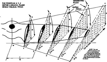
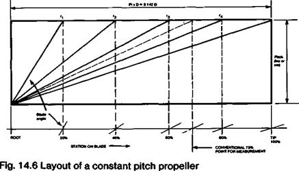
Whether or not the precise best angle for each aerofoil is known, the layout of a constant pitch propeller may be done by means of a diagram like that of Figure 14.6. Here, the desired pitch is represented on the vertical scale and expressed as a length (usually inches in English-speaking countries but centimetres or millimetres if SI units are used.) The basis of this figure is the notional distance the propeller would advance in one revolution if it were literally screwing itself through a solid medium like a screw or bolt This is, indeed, the origin of the words ‘airscrew’ and ‘pitch’ in this connection, by analogy with the pitch of the thread on a bolt. (The idea of ‘slip’ of a propeller as indicated in Figure 14.4, also originates here. Slip of a propeller blade is the angle of attack of the blade to the relative airflow and has no other meaning.) The distance that each segment of blade travels as the propeller rotates is represented by the horizontal scale. The extreme tip follows the circumference of a circle whose length is found from the standard circle formula:

C = 3.142 x D

On such a diagram the same scale proportion must be used for both horizontal and vertical scales. By ruling a number of straight lines radiating from the lower comer of diagram, the actual pitch angles required at each point are found and may be transferred directly from the drawing to the propeller block or master blade for production. If correctly done, this produces a propeller which will have, at one airspeed and one rate of rotation, every part of the blade at the most efficient angle of attack. This is why such a propeller is termed ‘constant pitch’. At typical result is shown in Figure 14.7.

Fig. 14.7 Layout of a constant pitch propeller blade.

The pitch, as a length, is represented by the vertical arrows. The distance round the hub travelled in one revolution is Pi x D at the tip and 2 Pi r at each radial

Station. Drawing courtesy J. Lnenicka.

It is clear from the above that at other airspeeds than the one for which the propeller is designed, even if the the rate of rotation is the same, the angle of attack will nowhere be at its best. This emphasises again that the propeller should be matched to the engine. It may be that a particular engine can turn a propeller of a certain diameter and pitch, at a certain rate. A model may be designed to fly at a speed which corresponds to this pitch. If, however, the model has more drag than anticipated it will not achieve the designed speed and the propeller will not be at its most efficient either. There is a double penalty. On the other hand, if the model drag is less than expected although a faster flight will result, the propeller will again not be at its best efficiency. A better result would be attained with a greater (coarser) pitch.

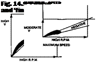
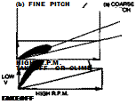
The constant pitch propeller just described is evidently ‘peaky’, in that it is designed foi best results at one speed and r. p.m. It is also efficient if the r. p.m. and flight speed vary ‘in step’ with one another, in a way that maintains the best angle of attack everywhere along the blade. This is indicated in Figure 14.8. There is at least a rough correspondence in reality since reduced engine power (low r. p.m.) results in lower flight speed. However, such a fortunate harmony is not likely to prevail at critical times. During take off, for instance, forward velocity is low and revolutions high. The coarse-pitch propeller blade is then at a higher angle of attack than optimum and may even stall (Fig. 14.9a). Racing aeroplanes have sometimes been incapable of taking off for this reason; the Schneider Trophy seaplane racers sometimes exemplifying this. Similarly, if, on a slow landing approach it becomes necessary to open the throttle to ‘go round again’ a stalled propeller could be disastrous. At the other end of the scale, a propeller designed for greatest efficiency in the take off mode, or climbing, will be working at lower angles of attack than optimum at high speed. Such a ‘fine pitch’ propeller will accelerate a model quickly from standstill but will lose efficiency rapidly as the airspeed increases (Fig. 14.9b).

BLADE LIFT AND PROPELLER THRUST

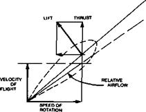
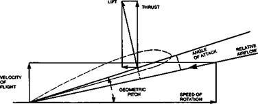
Figure 14.4 shows how the thrust produced by a propeller blade depends upon the speed ■ of rotation and the velocity of flight. The speed of the blade at any radial point, relative to the air, is a resultant of its speed around the circumference of the circle at its radial distance, and the forward velocity. The relative airflow is thus expressed in both speed and direction by the diagonal line appropriately labelled in the drawing. The angle of attack, measured from the geometric chord, relates to this relative flow line and is obviously less than the pitch.

Fig. 14.5 Angle of attack and thrust near the propeller hub.

So long as the angle of attack is greater than the aerodynamic zero of the section, lift will be produced but at right angles to the airflow, not to the propeller disc. The lift vector is thus inclined backwards relative to the plane of rotation. Resolution of the lift force demonstrates that the effective thrust is less than the lift and there is a component which must be added to the total blade drag.

At any radial station closer to the hub of the propeller than this, although the forward velocity must be the same, the speed of rotation is less. The relative speed and direction of the airflow at such a point is represented in Figure 14.5. To keep the blade here at the same angle of attack to the air, its angle to the disc plane must be increased. The effect of this is to tilt the lift vector considerably more against the rotation so that a large proportion of the force is available for thrust and more goes to resisting the rotation.

Since the relative flow speed is less than further out on the blade, the absolute magnitude of the lift force is less in any case, if the blade chord is similar.

For these reasons, the inner segments of a propeller are considerably less efficient as producers of thrust than the outer parts. Close to the hub the relative flow is almost directly along the axis of rotation and no thrust comes from this part of the blade at all. In practice, about 20% of each blade, measuring from the drive shaft outwards, may be neglected and, for the sake of all-round drag reduction, may be faired by a spinner with very little, if any, sacrifice of thrust.

PITCH

If a small segment of a propeller blade, at some distance from the hub, is viewed in cross section, as in Figure 14.3, the meaning ofpitch may be clarified. Conventionally, when a model propeller is being measured, using a simple pitch gauge, the flat, or flattish, back face of the blade is used as a reference. A radial station of 75% of the distance from the hub to the tip is generally used as the point for such a measurement, which yields the ‘rated’ pitch. This is usually given as a length (cm. or ins.), the reason for which appears below.

If the blade section is undercambered, a line tangential to the back face of the blade is used. However, most aerofoils on real propellers are not truly flat on one side. There is a true chord line which runs from the trailing edge to the leading edge. If this is used as the reference line for pitch calculations or measurements, as the diagram shows, the true geometric pitch will be greater than that based on the rated pitch. This may be part of the explanation for the very noticeable variations in pitch measured with the model flier’s gauge and the advertised rating of many commercially produced propellers. It should also be remembered that blade sections invariably change from root to tip, for structural reasons. The segments near the tip are usually thin and those nearer the hub considerably thicker. The geometric chord line may stand in a different relationship, at each place on the blade, to the underside tangential reference.

A further reference line on the drawing is also of importance. Every aerofoil section has an aerodynamic zero angle of attack. Only in the case of a symmetrical profile does this coincide with the geometric chord line. With cambered profiles, the aerodynamic zero line is at a greater angle to the propeller disc than either the conventional or the geometric reference. The aerodynamic zero line represents the angle of attack at which this part of a real propeller blade would produce zero lift and hence no thrust Such a condition can be

reached, for instance in a dive with the engine at low throttle. Beyond this negative angle the propeller becomes an air brake.

THE PROPELLER AS A ROTATING WING SYSTEM

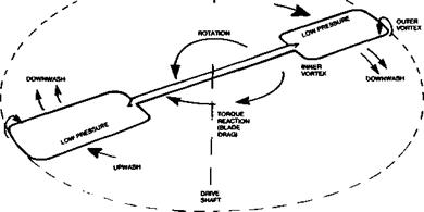
In more detail, each blade of a propeller is a wing which rotates. In some very simple forms the blades are paddle shaped as shown in Figure 14.2. The paddles are set at an angle now called the pitch, to the swept disc, so that they produce lift forces nearly at right angles to the plane of rotation. Drag forces resist the rotary motion, producing a torque reaction against the drive shaft. The aeroplane experiences this torque as a force tending to cause it to roll one way or the other, depending on the direction of propeller rotation. (Some aileron trim is required to counteract this.)

When the drag-torque reaction equals the shaft torque from the engine, the maximum rate of rotation is reached for the particular set of conditions. One way of increasing propeller efficiency is to reduce the drag of the blades, so allowing a higher rate of rotation for a given power input and hence, a larger difference in pressure behind the actuator disc and more thrust As with wings, blade drag is of two kinds, vortex-induced and profile drag.

Since the paddles produce lift in the same way as a wing does, by generating a pressure difference between the surfaces, there are rotating vortices at both the outer, or tip, end and at the inner end of each blade. The vortices produce drag, the amount depending, as with a wing, on the propeller’s equivalent of aspect ratio, blade planform and twist Because the blade travels at different speeds relative to the air, depending on the radial distance of each part of it from the hub, the shape and twist cannot be simply laid out as if for a wing. There are, however, equivalent techniques.

Also like a wing, a blade, or part of it may stall, producing very high drag with little lift Or, if a blade meets the air at a negative angle of attack it may produce negative lift which, in the case of a propeller, becomes a braking force.

All such faults and losses, inevitable as they are to some extent reduce the efficiency of a propeller so that it cannot achieve the Froude ideal. To minimise the losses is the aim

NOTE: IN OLD TEXTBOOKS, THE DIFFERENCE BETWEEN THE RELATIVE AIRFLOW AND THE ANGLE OF THE BLADE WAS REFERRED TO AS ‘SLIP’. IT IS ACTUALLY THE ANGLE OF ATTACK

of the designer who must nonetheless produce a propeller which will not fly apart under the considerable stresses caused by high rotational speeds, and will distort as little as possible under the air loads.

GENERAL POINTS ARISING FROM THE FROUDE EQUATION

The inflow factor is large if the increase of flow velocity produced by the propeller is large. If, for example, v, the flow speed increment added by the propeller to the slipstream, is equal to the flight speed, so that the speed of the slipstream behind the aeroplane becomes V + 2V = 3V, the ratio of v/V is 1.0 and the Froude efficiency equals 0.5. If the inflow factor is smaller, an increase in efficiency results: if v is only one tenth of V so that the

Fig. 14.2 A simple paddle-type propeller

slipstream velocity aft is V + (1/5 X V) or 1.2V, the ideal efficiency is 0.909. A given thrust can be obtained either by using a propeller of large diameter driven at a low rate, to produce a small pressure difference spread over a large disc area, or by a small propeller turning faster, creating a larger pressure difference spread over a smaller disc. The large diameter propeller, as the above examples show, would be much more efficient This point applies quite generally for model aeroplanes.

With full-sized aircraft propellers and helicopter rotors, a limitation to propeller diameter is set by the tip speed of the blades. If this approaches the speed of sound, efficiency falls off, quite apart from the high stresses and noise produced. Model propellers rarely enter such regions although it is possible for them to do so. There are other obvious limits for models and all aeroplanes to the practical diameter of a propeller. Ground clearance and undercarriage length usually prevent the use of the most efficient propeller diameter when the engine power is great

With model internal combustion engines, which are rarely geared down, rates o. rotation at maximum power are high and it is important, in competition flying, that the engine should run at its maximum power r. p.m. when required. A large diameter propeller will not develop more thrust than a small one, if it overloads the engine and prevents it reaching its best r. p.m. But it follows that if two engines of equal maximum power output are available and one runs at a lower r. p.m. than the other, more thrust will be obtained from a larger propeller on the slower engine. A crucial point here is the diameter to pitch ratio, of which more appears below.

The inflow factor also depends on the flight velocity. It is large if V is small and vice versa. If V is zero, as when die aeroplane is standing on the ground with engine running, no matter how much velocity the slipstream has, the propeller efficiency is zero. As the aircraft speeds up, efficiency increases. A limit is set to the attainable (level flight) speed of a model aeroplane by the total drag which will increase as the model accelerates until it comes to equal the thrust The rate of climb is subject to equivalent restrictions. If the drag is reduced by some aerodynamic improvement the potential will not be fully realised unless the propeller is changed to one which reaches its maximum efficiency at a higher speed. Every change to the aircraft requires a change to the propeller, if the best performance is to be attained.

On the other hand, if a propeller is designed very exactly to reach its peak efficiency at a particular flight attitude, speed and power, it will, at all other times, be working ‘off design’ and will be less efficient In particular, take-off performance, when propeller efficiency is bound to be low because V is small, will suffer if a high speed propeller is used. Racers need to take off smartly and accelerate to their best speed quickly. With simple propellers, some compromise has to be struck. With aerobatic models a propeller which has a narrow peak of efficiency will perform badly, because the airspeed varies constantly during the aerial pattern flying. In a vertical climb, V is low, yet the climb must be maintained. Yet rapid acceleration and high entry speed is needed for some manoeuvres. A propeller with a wide tolerance is required. The same applies, though with less urgency, to sport flying models generally.

Propellers

14.1 THE PROPELLER AS AN ACTUATOR DISC

Early research on propellers, by Rankine and Froude in the 19th century, was concerned with ships’ water screws, but the basic equations of that time remain valid. The propeller was treated as an ‘actuator disc’ which transferred power from the drive shaft to the fluid medium. In the first instance, no attention was paid to the details of the propeller, number of blades and blade shape. The idea was to establish the main principles first, thus opening the way for systematic trials and tests of various propeller forms.

14.2 PROPELLER EFFICIENCY

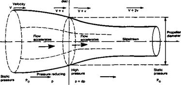
In Figure 14.1 the propeller is represented by a disc of diameter D. It is assumed that the rotation of the blades causes a reduction of pressure over the entire front face of the disc, from Po, the static air pressure at some distance in front of the aeroplane, to p at the disc. The energy transferred to the air by the propeller causes an increase of pressure by some relatively small amount labelled dp (where the small d stands for ‘a relatively small

Fig. 14.1 The propeller as an actuator disc

206

difference of). The air pressure just behind the disc is then p + dp. Far behind the disc the pressure returns to the static value, Po – The assumption that the pressure change is evenly spread over the whole disc area is false, particularly near the hub of a real propeller, but this obvious simplification and others are taken care of by recognising that no real propeller will be as efficient as the theoretical actuator disc.

Propeller efficiency is defined as the ratio of power supplied to the propeller by the drive shaft, to the useful work or power output i. e.

Подпись:useful power output _ Thrust x Velocity shaft power input Power

The difference in pressure between the front and rear of the disc produces thrust The total thrust can be found very simply by multiplying the difference, dp, by the disc area, which is found from the usual formula for area of a circle. Hence thrust = 0.7854 x D2 x dp, where D is the diameter.

As the diagram shows and as Bernoulli’s theorem leads us to expect (see 2.12), the reduced pressure in front of the disc causes the air to accelerate towards the propeller, V, which corresponds to the airspeed of the aeroplane, thus becoming V + v as the air passes through the disc. Behind the propeller, because of the increased pressure there, the flow accelerates away so the velocity increases further to V + 2v some distance behind. Half the increase of ‘slipstream’ velocity thus occurs ahead of a propeller and half behind it (This is why loose objects such as grass clippings or the end of model flier’s tie flapping loose, may be drawn into the propeller disc.) The slipstream diameter contracts both in front of and behind the propeller, as shown.

The ratio of v to V, the velocity of flight compared with the increment of flow speed through the disc, is of great importance and is termed the ‘inflow factor*, often represented in formulae by a tagged letter a, thus: Inflow Factor = a’ = v/V.

Подпись: T x V Tx (V + v)

Подпись: Thrust x Velocity Thrust x (V + v)
Подпись: Froude efficiency =

The Froude or ‘ideal’ efficiency of a propeller is found by relating thrust to flight speed and the inflow factor. The figure resulting is always less than 1.0. The equation is:

The thrust factor cancels out and since v/V = a’, the formula simplifies to:

Подпись: Ej =_J___

1 + a’

It is now possible to measure the actual thrust, and inflow factor, of any real propeller and compare the figures with the Froude ideal, which determines an absolute limit at a particular airspeed and power input Exceptionally well designed propellers may exceed 90% efficiency at best. A crude propeller, even though looking something like the right shape, may only achieve 50% or so efficiency. It is clear that no model flier can afford to neglect the propeller, since a bad choice may be equivalent to using a motor with forty percent less power output

MASS BALANCING

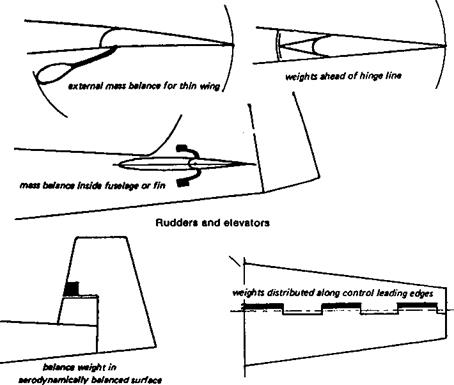
Mass balancing is achieved in many different ways on full-sized aircraft. In some cases a lead weight is mounted on an arm projecting ahead of the hinge line. The arm and weight may be concealed within the wing, fin or fuselage, but sometimes this is not possible and the mass balance weight protrudes, as a source of parasite drag. In other cases, control surfaces are built with portions projecting ahead of the hinge line, with the balance weight inside. The projection may be concealed or used, for example on a Frise aileron, as a means of overcoming adverse yaw in turns, or, on elevators and rudders, as an aerodynamic balance to reduce loads for the pilot. In models, similar devices may be useful if flutter arises, though the need for aerodynamic balancing is rare. Complete mass balancing is not always necessary, since within the speed range of a particular aircraft, flutter may be a problem only for some of the controls at the highest speeds, and even these may require only partial balancing. Since mass balancing adds weight, it should not be used if not essential.

Even with the suggested precautions, most aircraft have a critical airspeed beyond which flutter of some member or other will begin. In full-sized sailplanes, for example, flutter may start sometimes even below the nominal ‘red line’ or structural ‘never-exceed – airspeed’. This can occur if the control linkages are worn with use and hence have become sloppy. If no further mass balancing or structural stiffening is practicable (if, for example, the aircraft would become too heavy after such modifications) the only solution is to fly always below the critical flutter airspeed. The modeller often does not know what this speed is until his model begins to flutter, and unfortunately, this may result in rapid loss of control or the radio gear being damaged by severe vibrations, heavy oscillating loads, etc. Once started, flutter is very hard to stop. Only a reduction or airspeed will be effective in damping the oscillations down, and if it happens to be the elevator or flaps that are involved in the fluttering, speed control may be impossible. Quite apart from the more predictable effects of poor stability, radio or servo failure, and pilot error in exceeding the structural limits of the model, some apparently inexplicable mid air break ups of model aircraft are caused by flutter. In other cases, models can be seen or heard to flutter quite violently, yet survive unharmed. Quite small variations in structure will make a difference. For example, the stiffening effect of tissue paper or silk covering as opposed to

Fig. 13.10 Mass balancing

the flexibility of plastic film is well known. A heavy piece of balsa built into a trailing edge may encourage early onset of wing flutter, when an otherwise identical model may escape, and so on. As usual, theory is useful to help explain what went wrong, but unless the model designer is prepared to spend many hours in calculations, he will have to rely on practical experience combined with an intelligent appreciation of the forces involved, when a new model is under consideration.

14

FLUTTER

Any hinged control surface on a model may flutter. Flutter is an oscillation or violent shaking to and fro of the control surface, and it may set off sympathetic flutter in the wings or tail, or in other hinged members. In some cases, such flutter may be mild and almost harmless. The control surface affected vibrates slightly at certain airspeeds, possibly emitting an audible buzzing, but the oscillation does not build up and ceases as soon as the air speed drops. In other cases the flutter builds up rapidly and the model becomes uncontrollable, sheds control surfaces, or breaks up, with very little warning. The operator may have no idea what happened. The incident may be blamed on radio interference, or lack of structural strength.

In a simple case of flutter, the first cause is the inertia of the control surface itself. The effect may be simulated in an elementary way if a model fuselage with a hinged rudder disconnected from its control rod, is shaken from side to side violently. As the rear end of the fuselage moves, then reaches the end of its ‘shake’ and starts in the other direction, the hinged surface tends to bang over against its stops. It then follows the fuselage through the next movement, and when the fuselage stops moving to begin its return swing, the control surface bangs against the stops again in the other direction. When the model is flying, it is evident that such a control movement may be in phase with the oscillation of the fuselage. A rudder movement by the pilot, or a gust, causes the rear end of the model to swing. The rudder goes with this swing but when the fuselage stops, the rudder’s mass carries it further, which applies aerodynamic force tending to start the fuselage on its return swing. At the end of this second movement, the fuselage again stops and begins to swing back, but the rudder carries on, and again helps to push the fuselage on its way. At some critical airspeed the result will be a continuing oscillation, the rudder will bang violently from side to side and the fuselage with it Something, usually the rudder itself, will break if this

continues. Flutter of an elevator begins in the same fashion, and can be more dangerous since loss of the elevator control is usually disastrous for the model. Aileron flutter is even more common. Since wings are usually flexible, and ailerons large and relatively heavy, flutter is quite probable, especially at high speeds. Wings without ailerons, if too flexible in torsion, will also flutter at high speeds, the tip sections twisting to and fro almost as if they were hinged to the stiffer inboard panels. The twisting changes the angle of attack causing the wings to bend up and down rapidly.

Modellers who have never seen genuine wing flutter sometimes mistakenly refer to the normal up and down bending of wings under varying loads as flutter. Any wing will flex and must do so in flight Flutter of a wing is a rapid, rhythmic oscillation with simultaneous twisting. It is unmistakable, and, once started, hard to stop.

The case of the lightweight wing which flutters often arises when a model is based on an earlier free flight design, which was successful when trimmed for slow flight. Fitted with radio and controlled by rudder and elevator, the model may develop wing flutter when flown at speeds for which its wing was never really intended. In such cases the solution is to stiffen the structure.

If the torsional axis of the wing, i. e. the line around which the outer panels twist, lies ahead of the wing’s centre of gravity, flutter is sure to occur at some speed. The stiffening should be added to the leading edge, usually in the form of sheet balsa covering and vertical spar webbing, to produce a ‘D’ shaped torsion tube. The extra weight added near the leading edge also helps to bring the centre of gravity nearer to the torsional ‘hinge’ line. This is in effect a partial mass balance. Other forms of stiffening, such as diagonal ribs, or (as in some older types of wooden full-sized aircraft) by twin spars with diagonal strutting internally between the spars, is less effective because it does not move the centre of gravity of the structural members forward.

To prevent flutter it is essential for the hinged surfaces, especially on fast models, to be without slop, and for the wings and fuselage to be stiff. Stiffness is not the same thing as

Fig. 13.9 Wing flutter

strength. A fibre glass rod or arrow shaft is very strong, but is not very stiff, indeed the flexibility of glass combined with strength is its main recommendation to archers who use it for bows as well as arrows. Some sailplane models, like their full-sized counterparts, with slender fibreglass fuselages, are inviting tail flutter at high speeds. Secondly, the control rods and cables, and all their linkages, should be free from ‘play’ and again, as stiff as possible. This does not necessarily mean the pivots should be hard to move (although this, too, will help to prevent flutter), but the control rods themselves should not be easily flexed or bent by end loads. In models this is far from easy to arrange, but in general wooden push rods of adequate strength are usually stiff enough, whereas stranded cables, nylon ‘snake’ tubes, etc. are less so. Tubular metal (light alloy) arrow shafts are probably best of all, but costly. Finally, the control surfaces themselves should be as lightly built and as stiff as possible, and, where possible, mass-balanced. It is the mass of the control surface itself that is primarily responsible for flutter and it follows that if the mass can be reduced, flutter is less likely. However, if the control can be balanced so that its centre of mass, or centre of gravity, is ahead of the hinge line, the inertia of the balanced surface will prevent flutter altogether. Repeating the experiment with a rudder on a model fuselage, if the mass balancing is correctly done, the rudder will always be opposed to the fuselage oscillation, however violent
AIRBRAKES, SPOILERS AND FLAPS

As landing aids, split flaps are excellent Their advantage is that they create high drag with high lift coefficient, slowing the approach speed and steepening the glide angle, enabling better judgement of the point of touch down to be made. Operating loads on such surfaces are high at high airspeeds, and the modeller may well And the servo incapable of lowering the flaps fully if the model is not at the right speed (Fig. 13.6). As airbrakes, such flaps are usually beyond the servo’s power to operate when most needed.

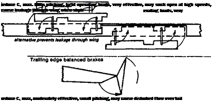
On sailplanes, various types of spoilers and airbrakes are used. The spoiler is a simple hinged surface which can be raised on the upper wing surface to disrupt the airflow and create more drag. It also reduces the maximum lift coefficient and raises the stalling speed, which is a disadvantage. The nose-down pitching moment may also be quite severe. Such spoilers are usually somewhat ineffective as drag producers, especially if mounted too far aft on the wing. They are also usually a source of extra drag in normal flight, since there is some air leakage from inside the wing to the upper surface around the spoiler. Unless they are very carefully fitted, when shut, they break the aerofoil profile’s contours and may cause separation or, on a laminar flow wing, transition. Some of the same criticisms apply to air brakes, which are raised vertically by some form of‘parallel ruler’ type of linkage (Fig. 13.6c), either on one surface of the wing, or both. These are usually much more effective than spoilers, especially at high speeds. They may be used to prevent the airspeed in prolonged dives from exceeding safe limits. This is useful in bringing sailplanes down out of strong thermals. There are two types of such parallel action brakes. In the first, the brakes are directly above one another, and extend equally above and below the wing. Between them there is a gap in the wing through which the air can flow from bottom to top surface. The effect on drag is very powerful, and the air leakage also reduces Cl markedly. On closing the brakes, the gap is sealed as far as possible by the brakes themselves, but there is still usually some leakage. To avoid this, the two leaves of the brakes may be separated, so that there is never any gap through the wing, each brake component retracting into its own sealed box inside. These brakes are slightly less effective, but interfere less with flight when retracted. It is very common to use brakes which extend from only one side of the wing, the upper or lower. These, like

Parallel brakes

spoilers, may cause some pitching moments, requiring re-trimming.

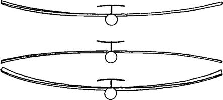
To avoid die leakage and fitting problems of brakes which retract into the wing, several types of trailing edge air brakes are possible, the best being those which are self balancing and so require only small power from the servo. These may sometimes cause pitching oscillations of the model due to the formation of rotating vortices behind them, which also’ may strike the tailplane. The brakes should be placed outboard of the tailplane, or a ‘T’ or ‘V’ tail used to ensure that the surface is clear of the turbulent wake.

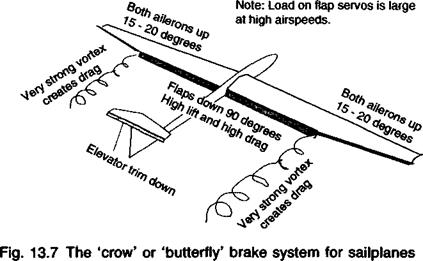
A very effective type of braking system which has become popular for sailplanes, is the so-called ‘crow’ or ‘butterfly’ mix. This normally requires sophisticated radio equipment

which permits the mixing of the ailerons and the flaps, together with the elevator.

When the action is required, the flaps, extending over the whole inboard section of the wing trailing edge from aileron ends to wing root, are arranged to go down hilly to 90 degrees or as close to this as possible. At the same time, both the ailerons move up together by IS to 25 degrees. The flaps create very high drag in this position and also at their outer end, adjacent to the ailerons, a strong vortex forms which adds yet more drag. The lift over, the flapped part of the wing remains high. The ailerons, because they are raised, remain effective as lateral controls. They effectively reverse the camber of the outer wing so the lift there is greatly reduced.

The braking effect is very powerful but there is usually a very strong nose-up pitch as the flaps go down. This requires the elevator to be coupled to the landing system to prevent the glider rearing up into a stall. Once the crow landing system is deployed, the model remains controllable for the final approach and touch down. A minor problem arises if the flaps, at their fully down position, make contact with the ground as the model lands. This can cause damage. Raising the flaps just before touchdown, or designing the model so that they cannot touch the ground in any position, will prevent trouble.

Parachute airbakes are excellent, providing they can be made reliable. The parachute itself may be housed in a special compartment in the fuselage, or following full-sized practice, in the bottom of the rudder. A light spring may be needed to ensure ejection of the brake ’chute. As a rule, such brakes are ‘one shot’ only, i. e. they cannot be retracted after deployment. Either the modeller must develop good judgement so that the parachute is never deployed at the wpong time, or some means of jettisoning it must be devised, so that an error can be retrieved. Full-sized sailplanes using such brakes usually possess other forms of air brakes as well, in case the parachute fails to deploy when needed, or in case the pilot inadvertently pulls the jettison handle instead of the deployment knob. The Polish ‘Zefir’ sailplane of 1958-62 possessed a brake parachute which could be retracted by means of a small hand winch, but the mechanical complications were considerable and the device was not used on later aircraft. Parachute brakes are a good choice for ‘flying wing’ models. Noel Falconer suggests a two point attachment for the brake ’chute, so that

deployment is more certain. One attachment may then be released to allow the parachute to trail, if an undershoot must be avoided.

Other forms of air brake are sometimes employed, including flaps sticking out of the side of the fuselage, split rudders which open like clam shells, and even broad wing struts which rotate through 90 degrees to give a braking effect. All these work to some extent but less effectively than the orthodox brakes described.