Our heavyweight helicopter equal in the world does not have
In Rostov started production of the most load-lifting rotary-wing car The Russian holding «Helicopt[...]

Everything about aircrafts and helicopters. News and events in aviation worldwide. Civil, transportation, military helicopters and airplanes.

Everything about aircrafts and helicopters. News and events in aviation worldwide. Civil, transportation, military helicopters and airplanes.

Everything about aircrafts and helicopters. News and events in aviation worldwide. Civil, transportation, military helicopters and airplanes.

Everything about aircrafts and helicopters. News and events in aviation worldwide. Civil, transportation, military helicopters and airplanes.


12.1 DEFINITIONS
Probably no aspect of aeronautics has caused so much confusion among model fliers as stability, so it is well to begin with some simple basic concepts and definitions.
An aircraft is stable if, after a disturbance, it tends to return to the flight attitude determined by its trim. This is not the same thing as saying it will always seek to return to straight and level flight If, and only if, the controls are centralised, a stable model will try to keep straight and level. If the controls are set for a steep dive, a stable aircraft will strive to retain this attitude. That is, it will go on diving until the trim is changed. A stable aircraft trimmed for a steady rate of turn at a suitable angle of bank will tend to continue in the steady turn, and so on for every other kind of trim. A model may be trimmed to fly inverted. If it is stable it will tend to remain inverted as long as the controls are set so. (Models with a fair amount of wing dihedral are seldom stable inverted, they tend to roll upright. An aircraft with no dihedral but with some degree of sweepback on the mainplane may be quite stable both upright and inverted.)
Gusts and other upsetting influences, including the actions of the pilot, frequently cause departures from the trimmed attitude but stability will strive to return the aircraft to the position prescribed by the controls wherever they are at a given moment There will always be some oscillations to and fro on either side of the trimmed attitude, somewhat like a pendulum, but the stable model will generally damp down such variations fairly quickly if left alone. A truly stable aircraft will usually fly more efficiently if it is allowed to settle down to its trim without constant interference from the pilot. Too many small twitches on the controls achieve litde but create extra drag and upset the flight.
For fast models, including cross country and ‘F3B’ sailplanes, it is important that when the model is at high speed, the fuselage should be aligned as closely as possible to the airflow. At low speeds, since parasite drag is less vital, this is not so important, though of course some reduction in drag will result if the fuselage is accurately aligned. Visual judgement of the model in flight is a rough guide but it must be a judgement of the fuselage’s angle relative to the true flight path. With gliders, the flight path is always inclined somewhat downwards, so a glider which, when trimmed, adopts an apparently ‘nose up’ attitude, will actually sink a little more rapidly due to extra drag than one which has the fuselage pointing directly along the path of glide. At high speeds the same applies – a model which, at maximum speed, appears to fly either nose up or down has its fuselage at an inefficient angle of attack to the airflow. It is best in design stages to think of the wing and tail as being fixed to give flight in one desired position, and then the angle of the fuselage is adjusted to this, rather than thinking of the fuselage as fixed with the wings set at some angle of incidence. Unless carefully designed, the flight line will certainly not be direct extension of the fuselage datum line on the plan (see Fig. 1.3). Trimming the model, by adjusting the centre of gravity and altering the relative angles, one to the other, of wing and tail, will determine the angle of attack of the wing. The flight path will then be at the angle to the wing. The fuselage should be set at this angle to give least drag in that condition. If suitable wind tunnel test results are available calculations can be of assistance. By studying the results given in Appendix 2, the Cl at which the model will operate may be found. From the section test results, corrected for aspect ratio and downwash effects, the geometric angle of attack at which this Cl develops may be estimated. If the wing is twisted and tapered, the average value for the wing as a whole should be taken, rather than that at one station, such as the wing root The method is explained with some examples in Appendix 1.
The validity of this method depends on the model in practice being correctly trimmed at the designed Cl, and the wing profile being accurate and reproducing fairly closely the wind tunnel figures. However, small errors of the wing setting angle will not make a great deal of difference in practice. The calculations should be regarded as a safeguard against gross errors in design, and in the workshop the modeller should maintain as high a standard of precision as is practical.
11.5 CANARD FOREPLANE DRAG
Some discussion of potential savings in vortex drag appears in Chapter 12. Canard foreplanes work in relatively undisturbed air and should be designed for laminar flow, to save parasite drag. The wake from the foreplane may turbulate the flow over some of the mainplane. ]5g
12
As part of the total drag of a model, the contribution of the tail unit is small, but the same rules apply as for wings. The vortex drag of tailplanes depends on the trim of the aircraft,’ which is discussed in Chapter 12. Otherwise, it becomes important at high speeds for aircraft with strongly cambered wings. The whole unit should be as small as possible commensurate with its necessary function of stabilising and steering. Some reduction of total drag is possible in theory if the three surfaces of fin, port and starboard tailplane, are
reduced to two by arranging the unit as a V tail, the angle between the two surfaces being then approximately 110 degrees. However, the required total area for such an arrangement is no less, and may be slightly more in practice, to achieve the same stability. In some flight positions it is possible for one side of a V tail to be stalled or to be blanketed by the other and this had been known to cause control difficulties. Since the elevator and rudder control effects are obtained by coupling only two hinged surfaces, there are some situations where full control is not available. If, for example, full elevator is applied, and full rudder is required at the same time, the angle to which one of the control surfaces is required to move is very large and it may stall. (Recovery from spins, requiring full rudder against the rotation with elevator down to unstall the wing has been found difficult or even impossible in some full sized ‘V’ tail aircraft)
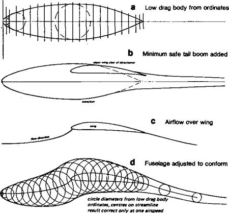
The flow over the fuselage is affected by the upwash and downwash caused by the wing. The approximate form of the streamlines is sketched in Fig. 11.2c and d. A way of reducing fuselage drag at one selected speed is to lay out the fuselage datum line as shown in Figure 11.2d, along the central streamline. Then the ordinates of a suitable low drag body are used, to construct a curved fuslage which follows the actual airflow. The result
|
|
will vary according to the presumed flow pattern. Without wind tunnel tests it is difficult to establish the correct form and even when done, it can apply only to one flight speed. Probably the gain is too slight to justify the effort.
In the early thirties, after considerable research, Alexander Lippisch designed the Fafnir 2 full-sized sailplane, which had a wing-fuselage junction resembling that of Figure 11.3. The fuselage was treated as if it were part of die wing, each longitudinal cross section being adjusted to produce lift, the idea being to carry the lift loading right across the span instead of allowing the fuselage to interfere. The result at one speed of flight was very good, but at other speeds it was less so. A somewhat similar, though less elaborately worked out, system was used on the ‘Fillon’s Champion’ model sailplane popular in the 1950s for free flight and radio control. It is probably better for all round performance to adopt the simplest low drag form, reduce cross sectional area as far as possible and add only the minimum fillets, for example, under the ‘armpits’ of a high wing sailplane, to fill in any sharp comers. Large fillets at the trailing edge may be necessary on some lowwinged aircraft, but in most cases the trailing edge should run straight to the fuselage, with a small fillet of the ‘radius’ type at the junction. Larger fillets here promote turbulence at all angles of attack except one. On sailplanes, refined fuselage design is aimed primarily at improving penetration at high speed. This should be borne in mind. A streamlined fuselage on an FI A (‘A2’) sailplane will possess only a very slight advantage since flight speeds are so low.
To reduce interference drag between wing and fuselage, or between any two components where they join, the first rule is that the angle of junction should not be less than 90 degrees. If two surfaces, or a stmt and another, larger component, join at a more acute angle, the air is forced to flow through a constricted channel and the drag increases rapidly as the angle becomes more acute. If such narrow channels cannot be avoided, they should be filleted; the fillet itself may be quite simple, but some care is needed to ensure that in itself it does not cause further flow separation problems (Fig. 11.4).
In designing fuselages for sailplanes, some laminar flow may be expected over the front portion, perhaps as far back as the wing. This suggests that the 60% laminar low drag bodies given in Appendix 3 should always be used for the nose at least Apart from very low drag, the advantage of these bodies, designed by Young, is that even when the fuselage is at a slight angle to the local airflow, when the model is yawed or when it flies at different angles of attack, the drag is not increased. The Young bodies (as opposed to old bodies) have a low drag range analogous to the low drag bucket of NACA ‘6’ series aerofoils. Cockpit canopies, access hatches etc. should fit closely and be free from steps or humps. Taking a hint from the full-sized sailplane built in 1975-9 by Gary Sutherland in Australia, a complete nose cone of‘Young’ form was used on Australian contest model sailplanes in 1982 and since copied widely. Laminar flow is thus almost assured. Aft of the point where the boundary layer becomes turbulent, skin drag will be high. It is the practice on most full-sized sailplanes to contract the cross section of the fuselage, producing a ‘pod and boom’ or tadpole shape. (See, for example, Figs. 4.6 & 4.7). This reduces the area of skin exposed to the tuibulent boundary layer. The gain is not very large and can easily be outweighed if the contraction is too sharp. This can cause flow separation. The effects are particularly bad if the fuselage upsets the airflow over the wing roots. Some well-known full-sized sailplanes suffer from this problem. The pilot can hear, at low speeds, the flow breaking away from the wing and fuselage just aft of the cockpit area, with quite noticeable effects on sinking speed. This is particularly likely when the
|
|
|
|
|
|
|
![]()
|
|
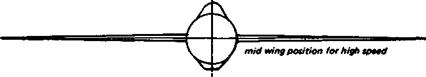
sailplane is in a turn, as when thermalling, since there is nearly always some slight slip or skid, causing cross flows. For this, reason the high wing position is probably better all round than the mid-wing mounting, which is ideal for high speed flight For models, there is only small advantage in the tadpole shape unless the fuselage cross section in front has to be increased to provide internal space for radio gear, etc. For free flight sailplanes the ‘stick’ type fuselage is best. However, for a radio sailplane, a low drag body should be used for the front ‘pod’, and after the contraction, a minimum tail boom of round section is all that is required to carry the tail.
Wheels if not retractable should be as thin as possible and enclosed in a well-fitted ‘spat’, with a streamlined strut On some racing models the wheels are arranged in tandem, one behind the other, which is aerodynamically good since two wheels in this position cause less drag than two separately, one lying in die wake of the other. If close together, the rear wheel acts as a rough fairing for the front one and drag may then be less than for a single wheel. If too far apart there may be a net loss.
11.2 COOLING DRAG
On racing models, attention should be given to airflow through the engine cowling. Drag inside the cowling is just as effective in slowing the model as drag outside it, and the smooth flow inside a good cowl will help engine cooling. The air intake should be designed to admit enough air and direct it where it is needed for cooling (usually through the fins on the cylinder head) rather than allowing it to disperse generally inside a chamber. Provision for exit of the heated air must also be made, not through a ragged hole somewhere at the rear, but through a smooth passage. Though unlikely to be noticeable in practice, the expansion of the air caused by the engine cooling function can be used to give a small increase of thrust if the air channels are arranged like those of a jet engine. The exit for the hot air should be larger than the intake.
11.1 THE IMPORTANCE OF PARASITE DRAG
As shown by Figure 4.10, parasite drag is a major problem for the designer of high speed models, racers and cross country or multi-task sailplanes. It is very much less important for free-flight and other duration models. The old controversy (in the days of ‘8 ounce’ unlimited rubber Wakefield duration models) between advocates of streamlined and ‘slabsided’ fuselages was partly based on a misunderstanding of this. The streamlined fuselage model gained very little in the glide, and only a little more in the faster part of the climb, from its lower drag coefficient To build a refined, streamlined fuselage always added some weight The rubber motor weight was then usually reduced, so sacrificing climb performance. In general, the same still applies, although with rubber quantities limited as they usually are, there may be a little extra weight to spare for structures and nothing is lost by refining the shape of the parasitic components (except the time taken in building them). The engine powered duration model, climbing at high speed with flaps up and at low Cl, gains more in the climb by a good fuselage design, and will not suffer for it in the glide.
There is hardly any model aircraft that could not be improved to some extent by greater attention to parasite drag. It is easy to recommend smooth and polished surfaces, sealing all gaps, burying all protuberances, such as control horns, dowel ends, rubber bands, etc. removing struts, and retracting undercarriages. The general principles are clear, but it is often very much less simple to achieve such perfection from the engineering point of view.
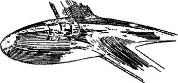
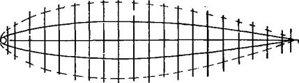
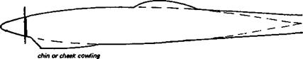
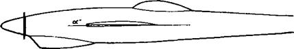
Any part of a model which does not contribute directly to the lift or which is not absolutely essential to control and stability should either be removed or buried inside so that the air does not flow over it. Where some component, such as the fuselage, wheel strut, engine, etc. simply must exist it should be of minimal cross section, faired, smoothed and polished. On power models, because of the disturbance caused by the propeller, flow over the fuselage is usually turbulent Little is to be gained by designing such a fuselage for laminar flow under power, although this does not mean the fuselage shape should be clumsy. Ordinates for the basic form of a streamlined body should be taken from Appendix 3. Depending on the length and cross sectional area (which should always be as small as possible compatible with good shape), the low drag body ordinates may be scaled up or down to give the plan and side view of the fuselage. It is hardly ever possible to retain the perfect form, but it should be regarded as the ideal and departures from it should be as small as possible. Probably the most likely alteration will be to simplify and extend the tail cone as suggested in Figure 11.1b, to make construction easier. This will have slight effects on drag. Protuberances such as cockpit canopies are undesirable from the aerodynamic point of view but if they are required they should be as low as possible and carefully faired. Where such things as silencers must protrude, they should be of streamlined form and carefully aligned with the average airflow, allowing as far as possible for the fact that the flow over trie fuselage itself is not straight On ‘duration’ models, propellers should fold or feather on the glide.
With all its disadvantages, the wind tunnel remains the easiest and most accurate method of testing wings and other aircraft components under standard conditions. Model fliers rightly regard such results as slightly doubtful, since the aerial conditions in which their aircraft fly are never as consistent as those of the laboratory. For instance, with all the effort put into reducing turbulence in wind tunnels, it is still not known what the turbulence’ of the air of the ordinary atmosphere is when the model is flying at different altitudes, different temperatures and in conditions of varying humidity, etc. The final test is always in real flight and even full-sized aircraft sometimes surprise their designers after years of preliminary studies and tunnel tests.
 |
Some model fliers, such as V. Seredinsky and T. J. Patrick, have attempted to test model wing sections by gliding small, specially constructed free flight models in calm conditions from the tops of hills. Useful results can be obtained in this way although there is a good deal of statistical ‘scatter’ in the figures. Such test methods are at the mercy of the weather. The models tend to wander off course, rendering exact timing and distance measurements very difficult. Indoor tests of the same kind rarely produce usable results because the distance available for the glide is too short to allow the model to settle to a constant airspeed. (See Figure 10.9)
With radio control, much more is possible and some preliminary testing has been done by a group in California, as reported by B. K. Rawdon. On occasions of true calm, gliding models can be timed at various trims over a series of long glides, with altitudes measured by photography and various triangulation techniques. Statistical scatter is still a problem but useful Figures have been found in this way.
There is a great deal of scope for refined instrumentation of large model aircraft. A model may be equipped with sensitive electronic devices to measure altitude and flight speed, angle of attack, and even air turbulence. The wing may be Fitted with pressure tapping perforations, just as wind tunnel models are, and wake rakes may be used. The data found in these ways may be recorded, either in die model itself or transmitted to the ground for immediate plotting. At the time of writing, no such results have been published,
although work along such lines is proceeding in a few places and research into remotely piloted military surveillance aircraft (effectively, large, long range model aeroplanes) is proceeding in many places. The future should produce some extremely important discoveries.
When the first edition of this book was written an attempt was made to include, in Appendix 2, all the known, reliable wind tunnel test results on aerofoils at model aircraft values of Reynolds number. There were not many such results and they were not easily found in the aeronautical literature. Some other useful material, notably from Lnenicka and Horeni in Czechoslovakia and from Dr Gates’ Group in Italy, came to the author*s attention too late for inclusion. In this edition, the old measurements, still not easily accessible to the ordinary reader, are retained and still provide useful information. To them have been added, with permission, some of the charts produced by Jaroslav Lncnicka. Although these have been published in Czechoslovakia, they are not widely known elsewhere.
Much more tunnel testing has been done since 1978 and it is no longer possible to assemble all into a single appendix of reasonable length. The Delft, Cranfleld and Notre Dame studies have been mentioned briefly in Chapter 9, and those seeking to know more will have to search the literature emanating from these institutions. The list of references at the end of this chapter will be a useful starting point. Most model fliers know already of the Stuttgart wind tunnel and the results from there published by Dr Althaus, in the series Profilpolaren fur den Modellflug. No serious aeromodeller should be without these volumes. The charts arc easily understandable by anyone who has read this book, and the brief text in German, describing the wind tunnel and the methods used in measurement, is not of fundamental importance from the modeller’s viewpoint With Dr Althaus’s permission, four test results on two Eppler and two Selig aerofoils carried out in 1986 are included in the Appendix.
During the years 1986—89 the team of Selig, Donovan and Fraser at Princeton University carried out a series of wind tunnel tests at model values of Re. The results were published in 1989 in a single volume, Soartech 8, Airfoils at Low Speeds. (See full details in the References listed below.) This represents by far the most extensive and valuable body of work on model wing profiles so far accomplished and for the serious model aircraft designer, like the Althaus volumes, it is indispensable.
The Princeton wind tunnel, described in the volume, was most carefully calibrated. Over sixty distinct profiles were tested but in many cases more than one test piece was used, for comparison. Where it seemed appropriate tuibulators were tried in different positions. More than 130 charts and associated tabulated figures were produced.
Of particular importance is the fact that all the test wings were made for the Princeton group by practising model aircraft builders, rather than by specialist wind tunnel craftsmen. Some of the profiles submitted were favourites of the modellers who made them, others, including the new SD series, were made to order. Every model wing tested was submitted to close scrutiny and departures from perfect accuracy were noted and published with the measured figures. Those using the results may therefore be confident that, with ordinary workshop equipment and sufficient attention to detail, it is possible to achieve results in a real wing which are similar to those from the Princeton tests.
Michael Selig, after leaving Princeton, became Professor in the Department of Aeronautical and Astronautical Engineering at the University of Illinois, Urbana. In 1993 a new programme of research and wind tunnel testing was announced, calling as before on ordinary modellers to make the required test wing sections. Results, when published, will be of great interest and importance.
The cautionary remarks made elsewhere in this chapter still apply.
The widespread availability of micro computers has rendered the working out of aircraft polars very much easier and software is on the market which enables the model flier without much aerodynamic knowledge, or mathematics, to produce a polar curve in a very short time. Before using such software it is wise to investigate the basis of the calculations incorporated in the programming. From the description given above, it is obvious that for a full computation some fairly sophisticated computer programming is necessary, with interpolation from wind tunnel results and allowances for wing taper, planform, and other factors. Much of this information may have to be fed to the machine by hand from the keyboard and the work involved in this is not negligible. If the software package does not call for such input, and if the time taken for the results to appear is very brief, the chances are that the programming is not in fact very thorough and the results will at best be crude in proportion. A program which does the task properly is likely to be quite costly and may take an appreciable time to run on the computer, as well as demanding more attention from the modeller using it
10.8 LIMITATIONS OF COMPUTED RESULTS
Even when the computer has been correctly programmed, the user should not expect the results to be correct in an absolute sense. That is, if the best L/D ratio is calculated at 1:20 at 35 m/s, it is very unlikely that these figures will be achieved exactly in flight There are always too many imponderables such as wind tunnel errors, faults in model construction and finish, variations of engine power, etc. which render the results more or less doubtful. What may be safely inferred from the calculations is that comparisons will remain valid. In other words if the computer indicates that this or that aerofoil or wing planform will yield an improvement in performance compared with another, this will probably be true and will show up in flight. The actual achieved L/D ratio or top speed may not be as calculated, but there should be an improvement if the new wing is built, finished and flown to the same standards of accuracy as the old one.