Category Modeling and Simulation of Aerospace Vehicle Dynamics

Displacement Theorems

The calculation of the MOI of a flight vehicle can be a tedious process. Only in recent times has it been automated by the use of CAD programs. However, you still may be challenged to provide rough estimates for prototype simulations. You can base these preliminary calculations on simplified geometrical representations and make use of two theorems that yield the MOI for shifted reference points and axes.

6.1.2.1 Point displacement theorem (Huygen’s theorem). The MOI of body В referred to an arbitrary point R is equal to the MOI referred to the c. m. В plus a term calculated as if all mass mB were concentrated in the c. m.

Ir = І в + (®brS brE — SbrSbr) (6.5)

or in the alternate form

= (6-6)

Compare the second terms on the right-hand sides with Eq. (6.1). They are the MOI of a particle with mass mB and the displacement vector sbr between the two reference points.

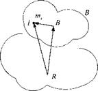
Proof: Introduce the vector triangle of Fig. 6.2

S iR — * IB + SBR

Displacement Theorems

into Eq. (6.1):

IR = E nii [(Sffl + Sbs)(Si’B + Sbr)E — (SiB + SBR)(SiB + *Bfi)]

і

= E mi^iBsiBE — s,[jSat) + (sbrSbrE — sbrSrr) E tn,•

I!

+ E rtiiSiBSBR + SBS E m/Sffl – E miSiBsBR – sBR E niiSiB і і і і

The last four terms are all individually zero because В is the c. m. The first term is according to Eq. (6.1)

‘У ^ Щ / (s lBsiBE s igs їв) — І в

і

and the second term is already in the desired form of Eq. (6.5).

Huygen’s theorem helps to build the total MOI of an aircraft from its individual parts. In this case R is the point of the overall c. m., whereas В is the c. m. of the individual part. We can modify Eq. (6.5) to encompass к number of individual bodies. Let B), be the c. m. of body B^. Then the total moment of inertia I^Bk of the cluster of & bodies Bk, к — 1, 2, 3,…, referred to the common reference point/? is

lfk = E 7t + ^mBl(sBtRSBtRE – SBkRSBtR) (6.7)

к к

and its alternate form

lRBk =T,(lBBk+™BtSBkRSBtR) (6.8)

к

According to Eq. (6.6), the right-hand side can also be expressed as the sum of individual MOIs:

к

An important conclusion follows: The total MOI of a cluster of bodies B^,k = 1, 2, 3,…, referred to the reference point R, can be calculated by adding the indi­vidual MOIs, also referred to R. In most practical cases, although not mandatory, R will be chosen as the overall c. m.

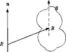
6.1.2.2 Parallel axes theorem. The axial MOI lRn of a body В about any given axis n is the axial MOI about a parallel axis through the c. m. В plus an axial term calculated as if all of the mass of the body were located at the c. m. В (see Fig. 6.3):

/fin = й/|и + mBh(sBRsBrE – sBRSBR)n (6.10)

Like any axial MOI, once the axis has been identified, it becomes a scalar with units in meters squared times kilograms.

Displacement Theorems

Fig. 6.3 Shifted reference axis.

Proof: Substitute Eq. (6.5) into Eq. (6.3) and obtain Eq. (6.10) directly.

Note that in Eqs. (6.5) and (6.10), the extra term can also be expressed by the tensor identity SBrSbrE – sBRsBR = SBrSBr, which is usually simpler to calculate.

Example 6.3 Tilt Rotor MOI

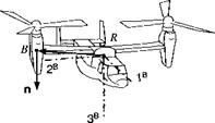
Problem. The axial MOI of the right tilt rotor is /д,, about the vertical axis [n]B = [0 0 1] (see Fig. 6.4). What is its axial MOI IRn wrt the aircraft c. m. R if the tilt rotor c. m. В is displaced by [sBR]B = sBr2 sBr,]1 What is the axial MOI of both rotors wrt R1

Solution. We apply Eq. (6.10) directly and obtain for one rotor hn = ln]B[l%]B[n]B +тв([й]в[^]ВМВ[«]В[£] – 1п]В[*вв]ВЫВ1п]в) /йзз = Ів33 + mB{slRi + 4,2 + S2m – slRl)

Irx = Івзі + mB(sBRl + sbr2)

The offset correction depends only on the square of the distance of the rotor axes from the aircraft c. m.; therefore, the axial MOI of both rotors is just twice the value

of /язз.

Displacement Theorems

Definition of Moment-of-lnertia Tensor

A material body is a three-dimensional differentiable manifold of particles pos­sessing a scalar measure called mass distribution. Integrating the mass distribution over the volume of the body results in a scalar called mass (see Sec. 2.1.1). If the integration includes the distance of the particles relative to a reference point, then we obtain the first-order tensor that defines the location of the c. m. wrt the refer­ence point. If the distance is squared, the integration yields a second-order tensor called the inertia tensor.

Definition: The inertia tensor of body В referred to an arbitrary point R is calculated from the sum over all its mass particles m, and their displacement vector siR according to the following definition:

Definition of Moment-of-lnertia Tensor(6.1)

where SiR is the skew-symmetric form of the displacement vector slR.

The notation IHR reflects the reference point as subscript R, the body frame as superscript В and summation over all particles. The expression siRsiRE— siRsiR — SiRSiR is a tensor identity, which you can prove by substituting components and multiplying out the matrices.

Подпись:

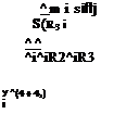
Подпись: X><(42 + 43) і І -У! miSiRlSiR3 і Подпись: ^ WlisiRі siR2 X)wK4, + 43) і І Подпись: ^ m і siflj S(R3 і ^ ^ ^i^iR2^iR3 У ^(4 + 42) і

For the body coordinates ]B with [.v,«]л = [siRl siR2 siR}], the MOI tensor has the component form

The MOI tensor expressed in any allowable coordinate system is a real symmetric matrix and has therefore only six independent elements. Its diagonal elements are called axial moments of inertia and the off-diagonal elements products of inertia. They have the units meters squared times kilograms. Some examples should give you more insight.

Example 6.1 Axial Moment of Inertia

The axial MOI /„ of the MOI tensor IR about a unit vector n through point R is the scalar

/„ = itIBn (6.3)

It has the same units of meters squared times kilograms as the elements of the MOI tensor. If we select the third-body base vector as axis and express it in body coordinates [nB = [0 0 1], then

hi hi hi

‘O’

О

о

If

hi hi hi

0

hi hi hi

_1_

The 3,3 element was picked out by n, justifying the name axial moment of inertia.

Example 6.2 Lamina

A lamina is a thin body with constant thickness (see Fig. 6.1). If the lamina extends into the first and second direction, then the polar moment of inertia about

Definition of Moment-of-lnertia Tensor Definition of Moment-of-lnertia Tensor

3B

the third axis is

I33 = hi + hi (6.4)

For a proof we set sm3 ~ 0 in Eq. (6.2), then

h 1 = m‘sk ’ 7зз = mi (4, + 42)

І І І

Substituting the first two relationships into the third completes the proof.

Inertia Tensor

We all have experienced the effect of mass, foremost as weight brought about by gravitational acceleration, or as inertia when we try to sprint. Yet, how do we sense MOI? If you are an ice dancer, you’ve had plenty of experience. Landing after a double or triple axel, you kick up plenty of ice to stop your turn. Actually, it is your angular momentum (MOI x angular velocity) that you have to catch, and the greater your MOI the greater the angular momentum.

As customary, we divide a body into individual particles and define the MOI of the body by summing over its particles. I shall introduce such familiar terms as axial moments of inertia, products of inertia, and principal moments of inertia. Huygen’s theorem and the parallel axes theorem will show us how to change the reference point or the reference axis. Because we are dealing mostly with vehicles in three dimensions, the moment of inertia ellipsoid, its principal axes, and the radii of gyration will give us a geometrical picture of this elusive MOI tensor. We will conclude this section with some practical rules that take advantage of the symmetries inherent in missiles and aircraft.

Attitude Dynamics

We have come a long way on the coattails of Sir Isaac Newton. His second law enables us to calculate the trajectory of any aerospace vehicle, provided we can model the external forces. For many applications we have to predict only the movement of the c. m. and can neglect the details of the attitude motions. Three – and even five-DoF simulations can be built on Newton’s law only. If you were to stop here, what would you be missing?

It is like the difference between riding on a ferns wheel, which transports your c. m., vs the twists and turns you experience on the Kumba at Busch Gardens amusement park. Attitude dynamics brings excitement into the dullness of tra­jectory studies and three more dimensions to the modeling task. Do you see the affinity between geometry, kinematics, and dynamics? Chapter 3 dealt with ge­ometry, describing position in terms of location and orientation; Chapter 4 dealt with kinematics; and now we characterize dynamics, consisting of translation (Chapter 5) and attitude motions (this chapter).

Attitude dynamics are the domain of Leonhard Euler, a Swiss physicist of the 18th century, whose name we have used before, but who now competes with Newton head on. We will study his law of attitude motion in detail. It has a strong resemblance to Newton’s law. Newton’s building blocks are mass, linear velocity, and force, whereas Euler’s law uses moment of inertia, angular velocity, and moment. But it gets more complicated. Mass is a simple scalar, whereas the moment of inertia requires a second-order tensor as a descriptor.

To prepare the way, we start with the moment-of-inertia (MOI) tensor and derive some useful theorems that help us calculate its value for missiles and aircraft. The geometrical picture of a MOI ellipsoid will help us visualize the tensor character­istics. The concept of principal axes will be most useful in simplifying the attitude equations.

Combining the MOI tensor with the angular velocity vector will lead to the concept of angular momentum. We will learn how to calculate it for a collection of particles and a cluster of bodies. Again, we will see how important the c. m. is for simplified formulations.

From these elements we can formulate Euler’s law. As Newton’s law is often paraphrased as force = mass x linear acceleration, so can Euler’s law be regarded as moment = MOI x angular acceleration. For freely moving bodies like missiles and aircraft, we use the c. m. as a reference point. Some gyrodynamic applications with a fixed point—for instance the contact point of a top—will lead to an alternate formulation of Euler’s law.

Gyrodynamics is a fascinating study of rigid body motions, and we will devote some time to it, both in reverence to the giants of mechanics, like Euler, Poinsot, Klein, and Magnus, and because of its modem applications in INS and stabilization of spacecraft. I will introduce the kinetic energy of spinning bodies and the energy

ellipsoid. Two integrals of motion are particularly fertile for studying the motions of force-free rigid bodies.

If you persevere with me through this chapter, you will have mastered a mod­ern treatment of geometry, kinematics, and dynamics of Newtonian and Eulerian motions. The remaining chapters deal with a host of applications relevant for today’s aerospace engineer with particular emphasis on computer modeling and simulation. So, with verve let us tackle a new tensor concept.

Six-Degrees-of-Freedom Simulations

The ultimate virtual environment for aerospace vehicles is the six-DoF simula­tion. No compromises have to be made or shortcuts taken. The equations of motion model fully the three translational and three attitude degrees of freedom.

Any development program that enters flight testing requires this kind of detail for reliable test performance prediction and failure analysis. Fortunately, by that time the design is well enough defined so that detailed aerodynamics and autopilot data are available for modeling. Yet, the development and maintenance of such a six – DoF simulation consumes great resources. Industry dedicates their most talented engineers to this task and maintains elaborate computer facilities.

However, even in the conceptual phase of a program it can become necessary to develop a six-DoF simulation. This need is driven either by the importance and visibility of the program or by the highly dynamic environment that the vehicle may encounter. A good example is a short-range air-to-air missile intercepting a target at close range. Its velocity and attitude change rapidly, resulting in large incidence angles and control surface deflections.

Six-DoF simulations come in many forms. They can be categorized by the iner­tial frame (elliptical rotating Earth or stationary flat Earth), by the type of vehicle (missile, aircraft, spinning rocket, or spacecraft), or by the architecture (tightly integrated, modular, or object oriented). We derive here the general translational equations for elliptical and flat Earth and leave the detail to Chapter 10.

5.4.3.1 Round Earth. The translational equations for round Earth—be it spherical or elliptical—follow the same derivation used in three-DoF models. As we will discuss in the next chapter, even for six DoF, the trajectory can be calculated as if the vehicle were a particle. Therefore, we can be brief. Newton’s law related to the J2000 inertial frame as applied to a vehicle with aerodynamic, propulsive, and gravitational forces is

mD’vlB = f а p + mg

The integration is executed in inertial coordinates, but the aero/propulsion data are most likely given in body coordinates. We make those adjustments together with the expression of the gravitational acceleration in geographic coordinates:

Подпись: (5.39)™[£>Ч]7 – [t]BI[frp]B +m[T}GI[gf

The main distinction with the three-DoF formulation, Eq. (5.31), lies in the han­dling of the aero/propulsive forces. Six-DoF simulations model the complex aero­dynamic tables and propulsion decks in body coordinates, whereas their simple approximations in three-DoF simulations can be expressed in velocity coordinates.

Another set of differential equations provide the position traces

Six-Degrees-of-Freedom Simulations(5.40)

which will have to be converted to more meaningful longitude, latitude, and altitude coordinates.

5.4.3.2 Flat Earth. Even in six-DoF simulations, with all of their emphasis on detail, the flat-Earth models are prevalent. All aircraft simulations that I know of are of that flavor, as well as cruise missiles and tactical air intercept and ground attack missiles. Earth E becomes the inertial frame, and the longitude/latitude grid
is unwrapped into a plane. Newton’s law takes on the form

mDEvEB = fap+mg

Six-Degrees-of-Freedom Simulations

The majority of flat-Earth six-DoF models express the terms in body coordinates, save the gravitational acceleration. By this approach the geographic velocity [vB]B in body coordinates can be used directly to calculate the incidence angles [see Eqs. (3.20-3.23)]. The conversion should be familiar to you by now. Transform the rotational derivative to the body frame

and coordinate accordingly

Six-Degrees-of-Freedom Simulations[fiB£]B[u£]B + – Ua, p]B + [T]BL[g]L (5.41) L J m

This is the translational equation of motion for flat Earth, implemented in six-DoF simulations. One more integration completes the set:

Six-Degrees-of-Freedom Simulations(5.42)

The body rates [SlBE]B are provided by the rotational equations (see next chapter), and the direction cosine matrix [T]BL is calculated by one of the three options provided in Sec. 4.3.

On the CADAC CD the GHAME6 simulation provides an example of the elliptical Earth implementation, and the flat-Earth model is used in SRAAM6. By running the sample trajectories, you can learn much about the world of six-DoF simulations.

Much more will be said in Chapters 8-10 about each of the three levels of simulation fidelity. At this point you can proceed directly to Chapters 8 and 9 to deepen your understanding of three – and five-DoF simulations. All of the necessary tools are in your possession. To tackle the six-DoF simulations, you first need to conquer the next chapter and its Euler law of rotational dynamics. Thereafter you are ready for the ultimate six-DoF experience of Chapter 10.

Let us pause and look at our newly acquired tools. The linear momentum, called motion variable by Newton, is related to mass and velocity bypB = mBv’B. It takes on the vector characteristics of the linear velocity, multiplied by the scalar mass of the vehicle. Our modeling elements, points and frames, are sufficient to define it completely. We could have carried over the superscript В of mass mB to define pBJ, but I decided to drop it because of the particle nature of body В in Newton’s law.

The other new vectors we encountered are the external forces. They consist of fa, the aero/propulsion surface forces, and mBg, the gravitational volume force. Both types must be applied at the c. m. of the vehicle. Only then can the vehicle be treated as a particle. In the next chapter, when we add the attitude motions to the translations of a body, we will derive the effect of shifting the forces to other reference points.

References

’Newton, I., Mathematical Principles of Natural Philosophy (reprint ed.), Univ. of California Press, Berkeley, CA, 1962.

2Franke, H., Lexikon der Physik, Frank’sche Verlagshandlung, Stuttgart, Germany, 1959. 3Grubin, C., “On Generalization of the Angular Momentum Equation,” Journal of Engi­neering Education, Vol. 51, No. 3, Dec. 1960, pp. 237, 238, 255.

Problems

5.1 Linear momentum independent of reference point. Show that the linear momentum pB of a body В wrt the inertial frame l and referenced to the c. m. В depends only on frame I and not on a particular point I.

5.2 Transformation of body points. The linear momentum pBi of a rigid body В relative to the inertial frame I and referred to an arbitrary body point B is shifted to another body point Вг – Prove the transformation equation

Pb2 — Pb, +mBnB, sBlB2

starting with the definition of the linear momentum of a collection of particles Eq. (5.2).

5.3 Satellite release. The space shuttle В releases a satellite S with its ma­nipulator arm at a velocity of

[u| ]B =[0 0 —at]

with the constant acceleration a. Its circular orbit is in the 17, 37 plane of the J2000 inertial coordinate system ]7 at an altitude of R and period of T, maintaining its 3B axis pointed at Earth’s center. Initially, the l7 and B axes are aligned, and the space shuttle flies toward the vernal equinox. Individual masses are mB and ms, respectively. Derive the equation for the inertial acceleration of the space shuttle first as a tensor DrvB, then coordinated [du^/dt]r, and finally in components.

Six-Degrees-of-Freedom Simulations

5.4 What’s the difference? The selection of the inertial frame for Newton’s law is determined by the application. The statement was made that for near-Earth orbits the J2000 inertial frame I can be used. What error is incurred by using mBDlv, B — /instead of the heliocentric reference frame H, mB DHvB = fl

(a) Derive the error term in tensor form.

(b) Coordinate it in heliocentric coordinates.

(c) Give a maximum numerical value for the error. You can assume a circular orbit of Earth around the sun.

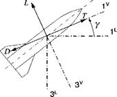
5.5 Planar trajectory equations of a missile. Derive the planar point-mass equations of a missile in velocity coordinates ]v with the dependent variables V as velocity magnitude and у as flight-path angle. Lift L and drag D are given, as well as the thrust T in the opposite direction of D.

(a) Derive the translational equations in an invariant form consisting of the velocity and position differential equations.

(b) Coordinate the equations into matrix form.

(c) Multiply out the matrix equations, and write down the four component equations.

Six-Degrees-of-Freedom Simulations

5.6 Centrifugal and Coriolis forces, who cares? An aircraft flies north with the velocity V at an altitude h above sea level. With the flat-Earth assumption we use Newton’s law in the simple form mBDEvf = /, but neglect on the right- hand side the Coriolis and centrifugal forces mB(2f2£/v| + ftE1flEISBE)- What are the values of these accelerations and their directions at 60-deg latitude (use h = 10,000 m, V = 250 m/s) in geographic coordinates?

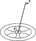
5.7 Hiking in the space colony. Wernher von Braun dreamed of a large space colony S orbiting Earth in the shape of a wheel with spokes. For artificial gravity the wheel was to be revolving with a>s about its 3s axis, and its close link with Earth was maintained by keeping the spin axis pointing toward Earth. You are hiking from the hub through a spoke toward the rim along the 2s axis. What are the Coriolis and centrifugal forces in ],s coordinates that you have to counteract to prevent you from bumping into the walls?

5.8 Space station rescue. A large, rigid, and force-free space station has a malfunctioning INS and begins to tumble in space. The chief engineer needs an alternate method to determine the angular velocity ujbi of the station В wrt the inertial frame I in order to supply it to the stabilizing momentum wheels.

A radio navigation system R is located on a long boom and displaced from the space station c. m. В by sRls. It measures its inertial velocity [vlRK and time rate

of change [d))^/dr|fl in space station coordinates ]B. Provide the chief engineer the matrix form of the differential equation [a>BI]B so that he can program it for the onboard computer. The mass of the boom and the navigation system may be neglected. (The orbital velocity [vjj]7 remains unaffected and is known from the orbital elements of the space station.)

Six-Degrees-of-Freedom Simulations

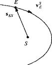
5.9 Kepler’s law from Newton’s law. Derive Kepler’s second law from Newton’s second law by considering a particle (Earth E) acted upon by a cen­tral force — lises/ses^, where S is the center of the sun and ji the gravitational parameter in meters cubed per seconds squared (± = Gmsun, G is the universal gravitational constant).

Six-Degrees-of-Freedom Simulations

Hint: Kepler’s second law states that the line joining Earth to the sun sweeps out equal areas in equal time. In other words, the area swept out in unit time is constant. With v| the velocity of Earth wrt the sun, this statement translates into the vector product Sesvse = const. You should prove that Newton’s second law reduces to this relationship.

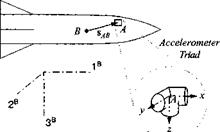
5.10 Accelerometer compensation, (a) An accelerometer triad A with its sensors mounted parallel to the missile body axes ]B is displaced sABB from the missile c. m. B. What are the three specific force components [aB]B acting on the missile, given the three accelerometer measurements aA]ri, the vehicle angular velocities

о)ВІУ‘ = p q r]

and their accelerations

d/dt[<wB/]B = [p q r]

(b) The acceleration triad is displaced by = [1 0 0] m, and the missile

executes steady coning type motions represented by

[a>BI]B = [0 sin t cos t] rad/s

What are the correction terms [Даa]b for the three accelerometer measurements?

Six-Degrees-of-Freedom Simulations

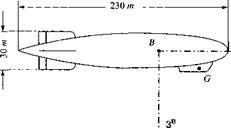
5.11 Burp of Graf Zeppelin. In October 1924 the Graf Zeppelin crossed the Atlantic on its maiden voyage under the command of Dr. Hugo Eckener. Midway it encountered a gust that caused the ship to pitch up at a constant 10 deg/s and incremental load factor of 0.1 g. What was the linear acceleration that Dr. Eckener experienced in the gondola at point G in Zeppelin coordinates? The displacement from the ship’s c. m. is [5Ig]b = [—90 0 —15] m.

Six-Degrees-of-Freedom Simulations

Five-Degrees-of-Freedom Simulations

If the point-mass model of an aerospace vehicle, as implemented in three-DoF simulations, does not adequately represent the dynamics, one can expand the model by two more DoF. For a skid-to-tum missile pitch and yaw attitude dynamics are added, whereas for a bank-to-tum aircraft, pitch and bank angles are used. Euler’s law could be used to formulate the additional differential equations. However, the increase in complexity approaches that of a full six-DoF simulation. To maintain the simple features of a three-DoF simulation and, at the same time, account for attitude dynamics, one adds the transfer functions of the closed-loop autopilot to the point-mass dynamics. This approach, with linearized attitude dynamics, is called a pseudo-five-DoF simulation.

The implementation uses the translational equations of motion, formulated from Newton’s law and expressed in flight-path coordinates. The state variables and their derivatives are the speed of vehicle c. m. wrt Earth: V — vEfi | and dV/dV, the heading angle and rate x and dx/dt; and the flight-path angle and rate у and dy/dt. One key variable, the angular velocity of the vehicle wrt the Earth frame a>BE, is not available directly because Euler’s equations are not solved. Therefore, it must be pieced together from two other vectors where V is the frame associated with the geographic velocity vector vf of the vehicle. The two angular velocities can be calculated because their angular rates and angles are available from the autopilot. The incidence rates are obtained from angle of attack a, sideslip angle /3, and bank angle ф

u>riv = f(a, a, p, $) skid-to-tum u>BV = f(a, d, ф, ф) bank-to-tum

and the flight-path angle rates

WVE = fix, X, r, y)

Thus, the solution of the attitude differential equations is replaced by kinematic calculations.

We formulate the translational equations for near-Earth trajectories, invoking the flat-Earth assumption and the local-level coordinate system. Application of Newton’s law yields

mDEv = /ДіР + mg

with aerodynamic, propulsive, and gravity forces as externally applied forces. The rotational time derivative is taken wrt the inertial Earth frame E. Using Euler’s
transformation, we change it to the velocity frame V

DvvEB + nVEvEB = ^-+g m

and use the velocity coordinate system to create the matrix equation

Подпись: [Dv(5.35)

The rotational time derivative is simply [DvvB]v — [V 0 0]. The aerodynamic and thrust forces are given in body coordinates, thus [fa, p]v — [TRV[fa. pR, whereas the gravity acceleration is best expressed in local-level coordinates [g]v — [T]VL[g]L. With these terms and the angular velocity

—X sin у

Подпись:[a>VEf = у

X cos у

Five-Degrees-of-Freedom Simulations Подпись: (5.37)

we can solve Eq. (5.35) for the three state variables V, x, and у

Подпись: d SBE dt Five-Degrees-of-Freedom Simulations Подпись: (5.38)

The vehicle’s position is calculated from the differential equations

These are the translational equations of motion for pseudo-five-DoF simulations. The details, and particularly the derivation of Eq. (5.36), can be found in Chapter 9. Note that a singularity occurs at у = ±90 deg.

Pseudo-five-DoF simulations have an important place in modeling and simula­tion of aerospace vehicles. They can easily be assembled from trimmed aerody­namic data and simple autopilot designs. Surprisingly, they give a realistic picture of the translational and rotational dynamics unless large angles and cross-coupling effects dominate the simulation. Trajectory studies, performance investigations, and guidance and navigation (outer-loop) evaluations can be executed success­fully with pseudo-five-DoF simulations.

Chapter 9 is devoted to much more detail. There you find examples for aerody­namics, propulsion, autopilots, guidance, and navigation models, both for missile and aircraft. The CADAC CD offers application simulations of air-to-air and cruise missiles AIM5, SRAAM5, and CRUISE5.

Three-Degrees-of-Freedom Simulations

During preliminary design, system characteristics are very often not known in detail. The aerodynamics can only be given in trimmed form, and the autopilot structure can be greatly simplified. Fortunately, the trajectory of the c. m. of the vehicle is usually of greater interest than its attitude motions, and, therefore, the simple three-DoF simulations are very useful in the preliminary design of aerospace vehicles.

Newton’s second law governs the three translational DoF. The aerodynamic, propulsive, and gravitational forces must be given. In contrast to six-DoF simula­tions, Euler’s law is not used to calculate body rates and attitudes; therefore, there is no need to hunt for the aerodynamic and propulsive moments.

Suppose we build a three-DoF simulation for a hypersonic vehicle. We use the J2000 inertial frame of Chapter 3 for Newton’s law. The inertial position and velocity components are directly integrated, but the aerodynamic forces of lift and drag are given in velocity coordinates. Therefore, we also need a TM of velocity wrt inertial coordinates to convert the forces to inertial coordinates.

The equations of motion are derived from Newton’s law, Eq. (5.9):

mD’vg = fap + mg (5.28)

where m is the vehicle mass and vlB is the velocity of the missile c. m. В wrt the inertial reference frame I. Surface forces are aerodynamic and propulsive forces fa p, and the gravitational volume force is mg. Although v’B is the inertial velocity, we also need the geographic velocity vB to compute lift and drag. Let us derive a relationship between the two velocities.

The position of the inertial reference frame I is oriented in the solar ecliptic, and one point I is collocated with the center of Earth. The Earth frame E is fixed with the geoid and rotates with the angular velocity u)EI. By definition the inertial velocity is v! B = D’sfii. where sBi is the location of the vehicle’s c. m. wrt point I. To introduce the geographic velocity, we change the reference frame to E

D1Sbi = DE$bi + EIe, Sbi (5.29)

and introduce a reference point E on Earth (any point), Sg/ = Sbe + %/, into the first right-hand term

DEsBi — Desbe + Desei = Desbe = vf

where Desei is zero because sei is constant in the Earth frame. Substituting into Eq. (5.29), we obtain a relationship between the inertial and geographic velocities

vb ~ vb +MEIsbi (5.30)

For computer implementation Eq. (5.28) is converted to matrices by introducing coordinate systems. The left side is integrated in inertial coordinates ];, while the aerodynamic and propulsive forces are expressed in velocity coordinates and the gravitational acceleration in geographic coordinates ]G. The details of obtaining the TMs are given in Chapter 3. We just emphasize here that we have to distinguish the two velocity coordinate systems. The one associated with the inertial velocity vB is called Jy, and the geographic velocity coordinate system is |v. With these provisions we have the form of the translational equations of motion:

Подпись: d^g dr = lTl’G([T]GUlfa, p]u + m[g]G) (5.31)

These are the first three differential equations to be solved for the inertial velocity components [Vg]1. The second set of differential equations calculates the inertial position

Подпись: d SBI dr= K]’ (5-32)

Both equations are at the heart of a three-DoF simulation. You can find them implemented in the CADAC GHAME3 simulation of a hypersonic vehicle.

If you stay closer to Earth, like flying in the Falcon jet fighter, you can simplify your simulation by substituting Earth as an inertial frame. In Eqs. (5.31) and (5.32) you replace frame I and point I by frame E and point E. The distinction between inertial and geographic velocity disappears, and the geographic coordinate system is replaced by the local-level system ]L:

Подпись: du| dr L

Подпись: d.sgg dr Three-Degrees-of-Freedom Simulations Подпись: (5.34)

= [T]LV[fa, p]v +rn[g]L (5.33)

These equations are quite useful for simple near-Earth trajectory work.

You will find more details in Chapter 8 with other useful information about the aerodynamic and propulsive forces. To experience an actual computer implemen­tation run the CAD AC GHAME3 simulation.

Simulation Implementation

When implementing Newton’s law on the computer, you have to answer many practical questions. What type of vehicle is being simulated: aircraft, missile, or satellite; is it flying near Earth or at great altitudes and hypersonic speeds; does the customer require high accuracy trajectory information or is he only interested in a quick, first-cut study? The answers determine the fidelity of your model.

The fidelity of a simulation is categorized according to the number of DoF it models. A rigid body, moving through air or space has six DoF, three translational and three rotational degrees. Newton’s law models the three translational degrees of freedom of the vehicle’s c. m., whereas Euler’s law (see next chapter) governs the three rotational degrees of freedom. Both together provide the highest fidelity.

However, for preliminary trajectory studies it may be adequate to model the vehicle as a particle. Only the translational equations apply, and the simulation is called a three-DoF model. If attitude motions have to be included, but a complete database is lacking, an interim model, the so-called pseudo-five-DoF simulation is used to great advantage. Two attitude motions, either pitch-yaw or pitch-bank, augment the three translational degrees of freedom. However, the attitude motions are not derived from Euler’s law, but from linearized autopilot responses. Ulti­mately, the full attitude motions, governed by Euler’s law, joined by Newton’s translational DoF form the full six-DoF simulations.

Besides fidelity requirements the form of the inertial frame categorizes a sim­ulation. Interplanetary travel demands the heliocentric frame; Earth-orbiting or hypersonic vehicles use the J2000 inertial frame; and slow, Earth-bound vehicles can compromise with the Earth as an inertial frame.

I will summarize the more important versions of Newton’s translational equa­tions, as they are employed in aerospace simulations. I will give you a glimpse of each category: three, five, and six degrees of freedom later. Chapters 8, 9, and 10 will provide the details.

Grubin Transformation

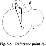
Now imagine that you are in the captain’s chair of the fictional starship Enterprise. The ship’s c. m. В is far behind your location Br. Before you exe­cute a maneuver, you want Mr. Spock to calculate the forces that you are exposed to because of your displacement sBBr from the c. m. of the spaceship.

This problem was addressed by Grubin3 and therefore carries his name. Similar to the Coriolis transformation, our goal is now to write Newton’s law wrt an arbitrary reference point Br of body В and move the additional terms to the right – hand side of the equation:

mBDIvIB = f + correction terms From Fig. 5.8 derive the vector triangle

Sfi/ = + Sfi,/

and substitute it into Eq. (5.8):

mBDIDIsBBr +mBD, D,sBri = f (5.26)

The second term is already in the desired form:

mB Dl DlsBri = mB D’vB

The first term, which will generate the apparent forces, is treated next. We will make use of the fact that DBsBBr — 0 because both points belong to the body frame В and apply the chain rule

mB Dl DlsBBr — mB D1 (DBsBBr + flBIsBBr) = mB D1 (flBI s BBr)

= mB D! nBIsBBr + mBftBI D1 sBBr = mB DIttBlsBBr + mBttBI(DBsBBr + ttB, sBBr)

= mB D! flBlsBBr + mBflBInBIsBBr

Substitution into Eq. (5.26) leads to Grubin’s form of Newton’s second law:

Grubin Transformation

Grubin Transformation

„ , , R I nB/nBIs BB centrifugal acceleration

m D vB — / — m < R. r

’ I + (£)’ G )sBBr angular acceleration

Sitting in your captain’s chair you experience two additional forces caused by centrifugal and angular accelerations. If you move to the c. m. of the spaceship, both forces vanish as your displacement vector sBBr shrinks to zero.

Example 5.8 Satellite with Solar Array

Consider a space station with a long empennage of solar arrays (see Fig. 5.9). The geometric center of the space station Br is a more important reference point than the rather obscure common c. m. B. Grubin’s transformation shows us how to set up the equations of motion. If the space station is rotating with the angular velocity uiBI, it is subject to the centrifugal acceleration ftB, flBISBBr and the angular acceleration D! nBISBBr • To develop the trajectory equations for the geometric center, we assume that the gravitational force is given in inertial coordinates If}1 = mBg}1, as well as the angular velocity and the position vector in body axes sbr,r.

The transformation matrix [T}BI relates the body and inertial axes. Then, from Eq. (5.27) we obtain the equations of motion in matrix form:

Подпись: m

Подпись: Fig. 5.9 Appendices.

df

Another important application of Grubin’s transformation is related to the specific force measurements of an INS. Seldom is the instrument cluster located at the c. m. of the missile. To determine the corrections that need be applied to the raw measurements, we use Grubin’s transformation to express the vehicle’s c. m. ac­celeration in terms of the center of the accelerometer cluster. The correction terms are the centrifugal and angular acceleration terms (see Problem 5.10).

We were able to derive the Coriolis and Grubin transformations of Newton’s law in an invariant tensor form, valid in any allowable coordinate system. The last ex­ample gave an indication of the conversion process for computer implementation. In aerospace vehicle simulations you will encounter many different ways of mod­eling the translational equations of motions. In the next section I will summarize the most important ones, but reserve the details for Part 2.

Coriolis Transformation

Unequivocally, Newton’s law must be referred to an inertial frame of reference I. Starting with such a frame however, we can use Euler’s transformation of frames and shift the rotational derivatives over to another, noninertial reference frame R. The additional terms are moved to the right side as apparent forces to join the actual forces. Our goal is to write Newton’s second law just like Eq. (5.9), but replace I by the noninertial reference frame R and include the additional terms on the right-hand side as corrections

mB DRVg = f + correction terms

We begin with Newton’s law in the form of Eq. (5.8) and introduce the vector triangle of displacement vectors shown in Fig. 5.7. В is the c. m. of body B, whereas the reference points R and I are any point of their respective frames

вві = SBR + Sri

Substituted into Eq. (5.8)

mBDID, sBR + mBD, D,sRl = f (5.23)

The second term represents the inertial acceleration of the reference frame and needs no further modification. However, both rotational derivatives in the first term must be shifted to the reference frame R. Let us work on this acceleration term alone:

D’D’sbr = D‘(DrSbr + nRIsBR)

= Dr(Drsbr + nR[sBR) + nRI(DRsBR + nR, sBR)

= DrDrsbr + DR(nRIsBR) + nRIDRsBR + nRlnRlsBR = DrDrsBr + 2 flRIDRsm + nRInR, sBR + (DRnRI)sBR

Подпись: mBDRvl Подпись: f ~ml Подпись: mRlvR +nRInRlsBR +(DRnRI)sBR +DID,SRI Подпись: Coriolis acceleration centrifugal acceleration angular acceleration linear acceleration Подпись: (5.24)

Substituting the definition of the relative velocity vR — DrSbr into Eq. (5.23) and moving all terms except the relative acceleration to the right yields the Coriolis form of Newton’s second law:

If the observer stands on a noninertial frame, he can apply Newton’s law as long as he appends the correction terms. There are four additional terms. The first three involve the body, and the last one relates only to the reference frame. The Coriolis acceleration acts normal to the relative velocity vRfi and the centrifugal accelera­tion outward. The angular and linear acceleration terms have no special name and appear only if the reference frame is accelerating.

Example 5.7 Earth as Reference Frame

Earth E is the most important noninertial reference frame for orbital trajectories. It has two characteristics that simplify the Coriolis transformation. Both the angular acceleration is zero, DI0,E’ — 0, and the linear acceleration of Earth’s center E vanishes, D1 D1sri = 0.

Thus, the simplified Coriolis form of Newton’s law emerges from Eq. (5.24):

mBDEvEB = f – mB(2EIeiveb + EIeiEIeisbe) (5.25)

with only the Coriolis and centrifugal forces to be included as apparent forces; sBE is the displacement vector of the vehicle c. m. wrt the center of Earth, vB is the vehicle velocity wrt Earth (geographic velocity), and flEI Earth’s angular velocity.

If you are the passenger in a balloon that hovers over a spot on Earth, you are only subject to the apparent centrifugal force. But when the balloon starts to move with vf, the Coriolis force kicks in. The faster the geographic speed, the greater the force, except if you fly north or south from the equator, then the cross product flEIvB vanishes.

The Coriolis force is responsible for the counterclockwise movement of the air in a hurricane on the northern hemisphere. Newton’s law governs the motions of the air molecules. As the atmospheric pressure drops, the depression draws in the air particles. Those south of the depression are moving north at velocity vB and are deflected by the Coriolis force mB2flEIvB to the east. The northern air mass veers to the west as it is pulled south. These flow distortions set up the counterclockwise circulation of a hurricane.