Our heavyweight helicopter equal in the world does not have
In Rostov started production of the most load-lifting rotary-wing car The Russian holding «Helicopt[...]

Everything about aircrafts and helicopters. News and events in aviation worldwide. Civil, transportation, military helicopters and airplanes.

Everything about aircrafts and helicopters. News and events in aviation worldwide. Civil, transportation, military helicopters and airplanes.

Everything about aircrafts and helicopters. News and events in aviation worldwide. Civil, transportation, military helicopters and airplanes.

Everything about aircrafts and helicopters. News and events in aviation worldwide. Civil, transportation, military helicopters and airplanes.


It can be shown that the pressure at the center of a circular vortex of strength y and radius a is the lowest pressure in the field of the vortex and the value is (px — yp2/a2), where px is the pressure at infinity and p is the local density. Therefore, if the pressure in the field to be positive everywhere, a2 < у 2p/pXI. That is, the radius of the vortex should be greater than or equal to у2p/p<x>. But in many occasions we are concerned with the case of a ^ 0. In such a case the resulting point vortex must be regarded as an abstraction. However, we can make a as small as we wish by making у small enough, or px large enough, but we shall still have a circular vortex and the induced velocity will be everywhere finite. The apparently infinite velocities which occur are due to the over-simplification of taking a = 0. Note that a similar lower limit is encountered for the size of a point source in two-dimensional motion, and is given by the same relation if у is taken as the strength of the source.
5.16 Point Rectilinear Vortex
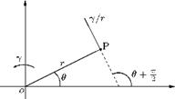
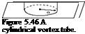
It is the limiting case of a circular vortex of constant strength у with radius a tending to zero. We have seen that any point outside a circular vortex of strength у, at distance r from the center, the velocity y/r is at right angles to r. If we let the radius a of the vortex tend to zero, the circle shrinks to a point. This limiting vortex of zero radius is called a point rectilinear vortex, or simply a point vortex of strength у. When the radius tends to zero, the cylindrical vortex tube shown in Figure 5.46 shrinks to a straight line and the vortex becomes a single rectilinear vortex represented by a point in the plane of motion, as shown in Figure 5.50.
If we take the origin at the vortex, the velocity at the point P(r, в) is represented by a complex number:
Yei(e+ 2 n) = r re—ie
We can relate this to the complex potential w = ф + as follows:
dw dw dz
dx dz dx
|
|
But z = x + iy, therefore:
![]() дф, дф дх dx u — iv.
дф, дф дх dx u — iv.
since u = дф/дх, v = —дф/дх.
Thus,
![]() u — iv
u — iv
iy iy
re‘e z
Integrating this, we get the complex potential w as:
w = iy ln z + constant
Here, the constant is irrelevant and hence can be ignored, then:
w = iy ln z
Note that the motion is irrotational except at the origin O where the vortex is positioned and so a complex potential exists, with a logarithmic singularity at the vortex.
If the vortex were at the point z0 instead of at the origin, the complex potential would be:
w = iy ln (z — z0).
It is essential to note that the velocity derived from the complex potential is the velocity induced by the vortex.
Consider a circular vortex of strength у, defined by:
2ny = circulation = nazf.
|
E
Figure 5.48 Velocity distribution along a diameter of a circular vortex. |
Thus,
1 2r Y = 2
Therefore, the velocity induced by this circular vortex is:
V’ = Y —2, r < a
a
т/ y
V = —, r > a. r
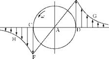
The velocities at all points of a diameter are perpendicular to that diameter, hence the extremities of the velocity vectors at the different points of the diameter will lie on a curve which gives the velocity distribution as we go along the diameter from —to to +to, as shown in Figure 5.48.
From points between C and D the velocity variation (along a diameter) is a straight line EAF, the variation from C to —to and D to +to is part of a rectangular hyperbola whose asymptotes are the diameter CD and the perpendicular diameter through the center A. The ordinates DE and CF, each represent the velocity у/a. Thus, if for a circular vortex of constant strength y, as the radius a decreases, DE will increase. Therefore, in the limit when a ^ 0 the velocity variation will consist of the rectangular hyperbola with the asymptote perpendicular to CD.
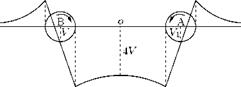
Now let us study the field of two identical circular vortices of radius a but with opposite vorticity (Z and – Z) at a finite distance apart, as shown in Figure 5.49. If the distance between their center BA is sufficiently large compared to a, as a first approximation, we can suppose that the vortices do not interfere and remain circular. For such a case their velocity fields may be compounded by the ordinary law of vector addition. The effect on the velocity distribution plot of A will reduce all the velocities at points near A on the diameter CD (see Figure 5.48) by approximately v = y/BA. The general shape of the velocity distribution plot for the pair of vortices will be as shown in Figure 5.49.
|
Figure 5.49 General shape of the velocity distribution for a pair of vortices. |
It can be seen that the center of each vortex is now in the field of velocity induced by the other and would therefore move with velocity v in the direction perpendicular to AB. Thus the vortices are no longer at rest, but move with equal uniform velocity, remaining at a constant distance apart. This is an application of the theorem that “a vortex induces no velocity on itself.” The vortices and velocity field shown in Figure 5.49 has its application to the study of the induced velocity due to the wake of a monoplane aerofoil at a distance behind the trailing edge.
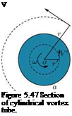
A circular vortex is that with the shape of its cross-section normal to its axis of rotation as circular. For example a single cylindrical vortex tube, whose cross-section is a circle of radius ‘a’, surrounded by unbounded fluid, as shown in Figure 5.46 is a circular vortex.
The section of this cylindrical vortex by the plane of motion is a circle, as shown in Figure 5.47.
Let us assume that the vorticity Z over the area of the circle is a constant. Outside the circle the vorticity is zero. Consider concentric circles of radii r’ and r, where r’ < a < r, as shown in Figure 5.47. Let the tangential speeds of the fluid motion on the circles of radii r’ and r are V and V, respectively.
We know that “the circulation in a closed circuit is the line integral of the tangential component of the velocity taken round the circuit in the sense in which the arc length (elemental length along the circuit) increases.” Thus, the circulation around the circles of radii r and r’, respectively, are:
 |
V ds and V’ ds,
where ds is an elemental arc length. Also, V and V’ are constants. Therefore:
V ds = о)лаг, r >
V’ ds = ожг’г, r < a
where ю is the angular velocity. Thus:
![]() 2nrV
2nrV
V
![]() 2nr’V’
2nr’V’
![]() V
V
when Г = r = a we have V’ = V = | аю so that the velocity is continuous as we pass through the circle.
From the above discussions, it can be inferred that the existence of a vortex implies the co-existence of certain distribution of velocity field. This velocity field which co-exists with the vortex is known as the induced velocity field and the velocity at any point of it is called the induced velocity. It is important to note that it is customary to refer to the velocity at a point in the field as the velocity induced by the vortex, but it is merely a convenient abbreviation of the complete statement that were the vortex to be alone in the otherwise undisturbed field the velocity at the point would have the value in question. In other words, when several vortices are present in the field, each will contribute to the velocity at a point.
For circular vortex the induced velocity at the extremity of any radius vector r joining the center of the vortex to a point of the fluid external to the vortex is of magnitude inversely proportional to r and is perpendicular to r. Thus the induced velocity tends to zero at great distances. The fluid inside the vortex will have velocity of magnitude proportional to r and therefore the fluid composing the vortex moves like a rigid body rotating about the center O with angular velocity ю = | f. The velocity at the center is zero. That is:
“a circular vortex induces zero velocity at its center."
Thus, a circular vortex alone in the otherwise undisturbed fluid will not tend to move.
The velocities at the extremities of oppositely directed radii are of the same magnitude but of opposite sense so that the mean velocity of the fluid within the vortex is zero. Thus, if a circular vortex of small radius be “placed” at a point in a flow field where the velocity is u, the mean velocity at its center will still be u and the fluid composing the vortex will move with velocity u. That is, the vortex will move with the stream carrying its vorticity with it.
Naturally occurring tropical cyclone, hurricane and typhoon which attains a diameter of from 150 to 800 kilometers, and travels at a speed seldom exceeding 25 kilometer per hour are circular vortices on a large scale. Within the area the wind can reach hurricane force, while there is a central region termed “the eye of the storm,” of diameter about 15-30 kilometers where conditions may be completely calm.
A rectilinear vortex is a vortex tube whose generators are perpendicular to the plane of motion. Now, let us have a closer look at some aspects of two-dimensional vortex motion. We know that the circulation
 |
Vortex tube
in an infinitesimal plane circuit is proportional to the area of the circuit. In a two-dimensional motion the vorticity vector Z at any point P, which is perpendicular to the plane of motion and whose magnitude is equal to the limit of the ratio of the circulation is an infinitesimal circuit embracing P to the area of the circuit. That is, the vorticity vector is by definition perpendicular to the plane of the motion, so that the vortex lines are straight and parallel. All vortex tubes are therefore cylinders whose generators are perpendicular to the plane of motion. Such vortices are known as rectilinear vortices. For our discussions in this section, let us consider the fluid between parallel plates at unit distance apart and parallel to the plane of the motion, which is half-way between them.
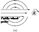
In Equation (5.3) the vector field is taken as velocity V. But the vector field need not be the flow velocity alone. The vector field can be force, mass Bow rate of a fluid, etc. Therefore, in general, the circulation may be defined as the line integral of a vector field around a closed plane curve in a flow field. If the vector is a force F, then the integral § F ■ ds is equal to the work done by the force. Taking the vector as pV, the mass flow rate per unit area, we can get a physical meaning of the circulation in the following way. Imagine a tiny paddle-wheel probe is placed [Figure 5.43(c)] in any of the flow patterns shown in Figure 5.43.
When the flow velocity on one side is greater than the other side, as in Figure 5.43(c), the wheel will turn. If the mass flow rate per unit area pV is larger on one side of the wheel than the other, then the circulation is different from zero, but if pV is the same on both sides as in Figure 5.43(b), then the circulation is zero. We shall show that the component of curl m along the axis of the paddle wheel equals:
lim — ® m ■ ds, (5.77)
dA^0 dA I
 |
 |
(c) (d)
Figure 5.43 Streamlines in: (a) a vortex, (b) parallel flow with constant velocity, (c) parallel flow with variable velocity, (d) flow around a corner.
where dA is the area enclosed by the curve along which we calculate circulation. The paddle wheel then acts as a “curl meter” to measure curl гіг; when the wheel does not rotate, curl гіг = 0. In Figure 5.43(c), curl гіг = 0 in spite of the fact that the streamlines are parallel. In Figure 5.43(d), it is possible to have curl m = 0 even though the streamlines go around a corner. In fact, for the flow of water around a corner curl гіг = 0. We must realize that the value of curl m at a point depends upon the circulation in the neighborhood of the point and not on the overall flow pattern.
Example 5.2
A cylindrical tank of 1 m diameter and 0.75 m height is filled with a liquid of relative density 0.9 up to 0.5 m from the bottom of the tank and the rest of the tank contains atmospheric air. The tank revolves about its vertical axis at a speed such that the liquid begins to uncover the base. (a) Calculate the speed of rotation and (b) the upward force on the cover.
Solution
The flow field described is shown in Figure 5.44.
(a) When the tank is static, the volume of oil is:
nR2zi.
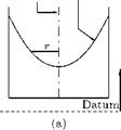
While rotating, a forced vortex is formed and the free surface will be a paraboloid CGD.
Volume of oil = Volume of cylinder ABFE — Volume of paraboloid CGD = nR2z — 2 nrz.
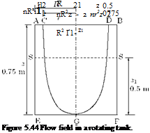 |
Since the volume of the paraboloid is equal to half the volume of the circumscribing cylinder, no oil is spilled out from the cylinder, therefore:
Show that a free vortex is an irrotational motion. A hollow cylinder of diameter 1 m, open at the top, spins about its axis which is vertical, thus generating a forced vortex motion of the liquid contained in it. Calculate the height of the vessel so that the liquid just reaches the top when the minimum depth of the free surface of the liquid (from the top) is 25 cm at 200 rpm.
Solution
The tangential velocity in a free vortex (excluding the core) is given by Equation (5.69) is:
Ve = ~,
r
where c is a constant. This field is potential if the vorticity content in the field is zero. The vorticity Z in polar coordinates is [Equation (5.2)]:
Е л. dh _ f din
r dr r Э6
In free vortex, the normal component of velocity qn = 0. Thus:
it dqt
r dr
We know that:
it_ w _c2
r r r2
and
dqt d Ґ c _ c
dr dr r) r2
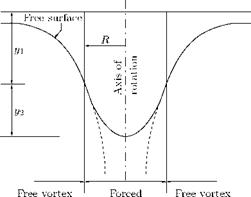
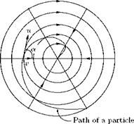
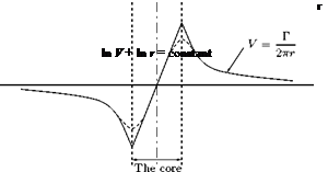
In the free vortex, v = c/r and thus, theoretically, the velocity becomes infinite at the center. The velocities near the axis would be very high and, skin friction losses vary as the square of the velocity, they will cease to be negligible. Also, the assumption that the total head H remains constant will cease to be true. The portion of fluid around the axis tends to rotate as a solid body. Thus, the central portion essentially forms a forced vortex. The free surface profile of such a compound vortex and the pressure variation with radius on any horizontal plane in the vortex is shown in Figure 5.42.
|
vortex Figure 5.42 Compound vortex. |
 |
For the forced vortex, the velocity at radius R is &R, while for the free vortex, from Equation (5.69), the velocity at radius R is c/R. Therefore, the common radius at which these two velocity will be the same is given by:
mR = c/R
R
A free spiral vortex is essentially the combination of a free cylindrical vortex and a radial flow. Before getting into the physics of free spiral vortex, let us see what is a radial flow.
Radial Flow
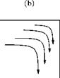
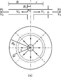
Examine the flow between two parallel planes as shown in Figure 5.40. In the flow the streamlines will be radial straight lines and the streamtube will be in the form of sectors. This kind of flow in which the fluid flows radially inwards, or outwards from a center is called a radial flow. The area of the flow will therefore increase as the radius increases, causing the velocity to decrease. The flow pattern is symmetrical and therefore, the total energy per unit weight H will be the same for all streamlines and for all points along each streamline if we assume that there is no loss of energy.
If Vr is the radial velocity and p is the pressure at any radius r, then the total energy per unit weight H becomes:
p V2
H =——— 1— = constant. (5.72)
Pg 2g
Assuming the flow to be incompressible (as would be the case of a liquid), by continuity, we have the volume flow rate Q as:
Q = area x velocity
= 2nrb x Vr,
 |
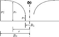 |
Figure 5.40 A radial flow: (a) streamlines, (b) pressure variation.
where b is the distance between the planes. Thus,
Substituting this into Equation (5.72), we get:
If the radial flow discharges to atmosphere at the periphery, the pressure at any point between the two plates will be below atmospheric (that is, subatmospheric); there will be a force tending to bring the plates together and so shut-off the flow. This phenomenon can be observed in the case of a disc valve. Radial flow under the disc will cause the disc to be drawn onto the valve seating. This will return to atmospheric and the static pressure of the fluid on the upstream side of the disc will push it off its seating again. The disc will tend to vibrate on the seating and the flow will be intermittent.
Now, let us find an expression for the pressure difference between two points on the same horizontal plane in a free vortex. For a free cylindrical vortex, the streamlines are concentric circles and there is no variation of the total energy with radius, that is:
— = 0.
dr
Also, by Equation (5.69), we have:
Let p1 and p2 be the pressures in two concentric streamlines of radii r1 and r2 which have velocities V1 and V2, respectively. Since there is no change of total energy with radius, for the same horizontal plane, by Bernoulli equation:
 (5.74)
Now, let us obtain an expression for the pressure difference between two points at radii R1 and R2 ,ona radial line, when a fluid flows radially inward or outward from a center, neglecting friction. Flow is radial and therefore in straight line so that r, the radius of curvature of the streamlines, is infinite, dH/dr = 0, and for all streamlines:
p V2
H =——- 1—– = constant.
Pg 2g
If p1 and p2 are the pressures at radii R1 and R2, respectively, where the velocities are V1 and V2:
P1 – P2 V| – V2
Pg 2g ‘
By volume conservation:
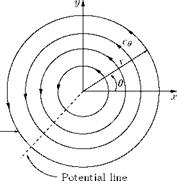
|
Figure 5.41 A free spiral vortex. |
It is evident from Equations (5.73) and (5.74) that the relation between pressure and radius and between velocity and radius is similar for both free vortex and radial flow. Both types of motion may therefore occur together. The fluid rotates and flows radially forming a free spiral vortex in which a fluid element will follow a spiral path, as shown in Figure 5.41.
Free vortex is an irrotational flow field in which the streamlines are concentric circles, but the variation of velocity with radius is such that there is no change of total energy per unit weight with radius, so that dH/dr = 0. Since the flow field is potential, the free vortex is also called potential vortex.
For a free vortex, from Equation (5.65), we have:
|
0= |
V |
|
|
dV |
dr |
g |
|
— |
+ — = |
0. |
|
V |
r |
|
V dV ~ + ~dr |
 |
or
Vr = c,
where c is a constant known as the strength of the vortex at any radius r. The tangential velocity becomes:
This shows that in the flow around a vortex core the velocity is inversely proportional to the radius (see Section 5.4). When the core is small, or assumed concentrated on a line axis, it is apparent from the relation V = c/r that when r is small V can be very large. However, within the core the fluid behaves as though it were a solid cylinder and rotates at an uniform angular velocity. Figure 5.38 shows the variation of velocity with radius for a typical free vortex. The solid line represents the idealized case, but in reality it is not so precise, and the velocity peak is rounded off, as shown by the dashed lines.
At any point in the flow field, by Bernoulli equation, we have:
![]() V2
V2
+ ^ + г = H. 2g
Substituting Equation (5.69), we get:
P c2
—— + 9- 2 + г = H
Pg 2gr2
At the free surface, — = 0. Thus, the profile of the free surface is given by:
Pg
This is a hyperbola asymptotic to the axis of rotation and to the horizontal plane through г = H, as shown in Figure 5.39.
 |
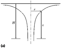 |
Figure 5.39 Free vortex: (a) shape of free surface, (b) velocity variation.
For any horizontal plane, z is constant and the pressure variation is given by:
Thus, in a free vortex, pressure decreases and circumferential velocity increases as we move towards the center, as shown in Figure 5.39.
The free vortex discussed above is essentially a free cylindrical vortex. The fluid moves along streamlines that are horizontal concentric circles; there is no variation of total energy with radius. Combination of a free cylindrical vortex and radial flow will result in a free spiral vortex.
Forced vortex is a rotational flow field in which the fluid rotates as a solid body with a constant angular velocity ю, and the streamlines form a set of concentric circles. Because the fluid in a forced vortex rotates like a rigid body, the forced vortex is also called Bywheel vortex. The change of total energy per unit weight in a vortex motion is governed by Equation (5.65).
The velocity at any radius r is given by:
|
V = юг |
|
From this we have: |
|
and |
|
V — = ю. r |
|
Substituting dV/dr and V/r into Equation (5.65), we get: |
|
dH юг — = —(ю + ю) dr g |
|
2ю2г g ‘ |
|
Integrating this we get: |
|
(5.66) |
|
H = ——- + с, g |
|
where с is a constant. By Bernoulli equation, at any point in the fluid, we have: |
|
p V2 H =——– + T)—+ z. pg 2g |
|
|
|
|
|
Note that, in the above equation and Equation (5.66), the unit of the total head is meters. Substitution of this into Equation (5.66) results in:
|
P |
-2r2 |
-2r2 |
||
|
+— “— |
+ z = |
z —– |
+ c |
|
|
Pg |
2g |
g |
||
|
P |
– 2 r2 |
|||
|
+ z = |
+ c. |
|||
|
Pg |
2g |
If the rotating fluid has a free surface, the pressure at the surface will be atmospheric; therefore, the pressure at the free-surface will be zero.
P
Replacing — with 0 in the above equation, the profile of the free surface is obtained as:
 |
|
Pg
Thus, the free surface of a forced vortex is in the form of a paraboloid.
Similarly, for any horizontal plane, for which z will be constant, the pressure distribution will be given by:
22
– = – rj – + (c – z). (5.68)
Pg 2g
The typical shape of the free surface and the velocity variation along a radial direction of a forced vortex are shown in Figure 5.37.
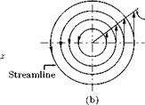
Vortex is a fluid flow in which the streamlines are concentric circles. The vortex motions encountered in practice may in general be classified as free vortex or potential vortex and forced vortex or flywheel vortex. The streamline pattern for a vortex may be represented as concentric circles, as shown in Figure 5.35.
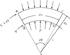
When a fluid flow is along a curved path, as in a vortex, the velocity of the fluid elements along any streamline will undergo a change due to its change of direction, irrespective of any change in magnitude of the fluid stream. Consider the streamtube shown in Figure 5.36.
As the fluid flows round the curve there will be a rate of change of velocity, that is, an acceleration, towards the curvature of the streamtube. The consequent rate of change of momentum of the fluid must be
|
Figure 5.35 Streamline pattern of a vortex. |
due to a force acting radially across the streamlines resulting from the difference of pressure between the sides BC and AD of the streamline element, as per Newton’s second law. The control volume ABCD in Figure 5.36 subtends an angle SO at the center of curvature O and has length Ss in the direction of flow. Let the thickness of ABCD perpendicular to the plane of diagram be ‘b’. For the streamline AD, the radius of curvature is r and that for BC is (r + Sr). The pressure and velocity at AD and BC are p, V, (p + Sp) and (V + SV), as shown in Figure 5.36. Thus, the change of pressure in the radial direction is Sp.
The change of velocity in the radial direction (as shown in the velocity diagram in Figure 5.36) is:
SV = VSO.
But SO = Ss/r. Thus, the radial change of velocity between AB and CD is:
Ss
SV = V—. r
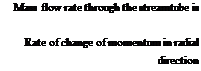 density x area x velocity p(b x Sr)V.
![]()
 |
(mass per unit time) x radial change of velocity VSs
(pbSr V)—- .
r
This rate of change of momentum is produced by the force due to the pressure difference between BC and AD of the control volume, given by:
F = [(p + Sp) – p]bSs. (5.61)
According to Newton’s second law, Equation (5.60) = Equation (5.61). Thus:
SpbSs = pbSrV zSs/r
P = pgh.
Therefore,
Sp = pgSh.
Substituting this into Equation (5.62), we get:
![]()
![]()
 |
Sh
PgT~ =
Sr
or
Sh _ V2 Sr gr
In the limit Sr ^ 0, this gives the rate of change of pressure head in the radial direction as:
The curved flow shown in Figure 5.36 will be possible only when there is a change of pressure head in a radial direction, as seen from Equation (5.63). However, since the velocity V along streamline AD is different from the velocity (V + SV) along BC, there will also be a change in the velocity head from one streamline to another. Such a change of velocity head in the radial direction is given by:
Rate of change of velocity head
in the radial direction = [(V + SV)2 — V2] /(2 g Sr)
VSV,
=——— (neglecting the products
g Sr
of small quantities)
V dV
=——– (as Sr ^ 0). (5.64)
g dr
For a planar flow (say in the horizontal plane), the changes in potential head is zero. Therefore, the change of total head H, that is, the total pressure energy per unit weight, in a radial direction, SH/Sr, is given by:
SH
— = change of pressure head + change of velocity head.
Sr
![]()
|
|
|
|
|
|
|
|