Our heavyweight helicopter equal in the world does not have
In Rostov started production of the most load-lifting rotary-wing car The Russian holding «Helicopt[...]

Everything about aircrafts and helicopters. News and events in aviation worldwide. Civil, transportation, military helicopters and airplanes.

Everything about aircrafts and helicopters. News and events in aviation worldwide. Civil, transportation, military helicopters and airplanes.

Everything about aircrafts and helicopters. News and events in aviation worldwide. Civil, transportation, military helicopters and airplanes.

Everything about aircrafts and helicopters. News and events in aviation worldwide. Civil, transportation, military helicopters and airplanes.


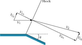
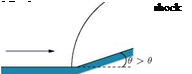
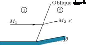
Consider the turning of a two-dimensional supersonic flow through a finite angle at a convex corner, as illustrated in Figure 9.32. Let us assume that the flow is turned by an oblique shock at the corner, as shown in the figure.
The flow turning shown in Figure 9.32 is possible only when the normal component of velocity V2n after the shock is greater than the normal component V1n ahead of the shock, since V1t and V2t on either side of the shock must be equal. Although this would satisfy the equations of motion, it would lead to a decrease of entropy across the shock. Therefore, this turning process is not physically possible. From the geometry of the flow shown in Figure 9.32, it follows that V2n must be greater than V1n. The normal momentum equation yields:
P1 + P1V12n = P2 + P2Vl – Combining this with continuity equation:
P1 V1n = P2 V2n
|
|
(a) Centered expansion (b) Continuous (simple) expansion
Figure 9.33 Centered and continuous expansion processes.
we obtain:
p2 p1 p1 V1n(V1n V2n) •
Because V2n > V1n, it follows that the pressure downstream of the corner should be less than the pressure upstream of the corner (p2 < p1). For this, the flow should pass through an expansion fan at the corner. Thus, the wave at the convex corner must be an expansion fan, causing the flow to accelerate. In other words, the shock wave shown at the convex corner in Figure 9.32 is a physically impossible solution.
In an expansion process, the Mach lines are divergent, as shown in Figure 9.33 and, consequently, there is a tendency to decrease the pressure, density and temperature of the flow passing through them. In other words, an expansion is isentropic throughout.
It is essential to note that the statement “expansion is isentropic throughout” is not true always. To gain an insight into the expansion process, let us examine the centered and continuous expansion processes illustrated in Figures 9.33(a) and 9.33(b). We know that the expansion rays in an expansion fan are isentropic waves across which the change of pressure, temperature, density and Mach number are small but finite. But when such small changes coalesce they can give rise to a large change. One such point where such a large change of flow properties occurs due to the amalgamation of the effect due to a large number of isentropic expansion waves is point P, which is the vertex of the centered expansion fan in Figure 9.33(a). As illustrated in Figures 9.33(a), the pressure at the wall suddenly drops from p1 to p2 at the vertex of the expansion fan. Similarly, the temperature and density also drop suddenly at point P. The Mach number at P suddenly decreases from M1 to M2. The entropy change across the vertex of the expansion fan is:
, T2 p2
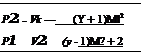
S2 – St = Cp ln – R ln.
T p1
It is seen that entropy change associated with the expansion process at point p is finite. Thus, the expansion process at point P is nonisentropic. Therefore, it is essential to realize that a centered expansion process is isentropic everywhere except at the vertex of the expansion fan, where it is nonisentropic.
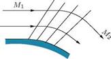
But for the continuous expansion illustrated in Figure 9.33(b), there is no sudden change of flow properties. Even at the wall surface the properties change gradually as shown in the figure, due to the absence of any point such as P in Figure 9.33(a), where all the expansion rays are concentrated. Therefore, the continuous expansion is isentropic everywhere.
The expansion at a corner (Figure 9.33(a)) occurs through a centered wave, defined by a “fan” of straight expansion lines. This centered wave, also called a Prandtl-Meyer expansion fan, is the counterpart, for a convex corner, of the oblique shock at a concave corner.
A typical expansion over a continuous convex turn is shown in Figure 9.33(b). Since the flow is isentropic, it is reversible.
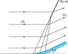 |
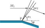
Compressions in a supersonic flow are not usually isentropic. Generally, they take place through a shock wave and hence are nonisentropic. But there are certain cases, for which the compression process can be regarded isentropic. A compression process which can be treated as isentropic is illustrated in Figure 9.31, where the turning of the flow is achieved through large number of weak oblique shocks. These kinds of compression through a large number of weak compression waves is termed continuous compression. These kinds of corners are called continuous compression corners. Thus, the geometry of the corner should have continuous smooth turning to generate large number of weak (isentropic) compression waves.
The weak oblique shocks divide the field near the wall into segments of uniform flow. Away from the wall the weak shocks might coalesce and form a strong shock as illustrated in Figure 9.31. We have seen that the entropy increase across a weak wave is of the order of third power of deflection angle в. Let the flow turning through an angle, shown in Figure 9.31, be taking place through n weak compression waves, each wave turning the flow by an angle Ав. The overall entropy change for this compression process is:
(in – it) ~ п(Ав)3 ~ пАв(Ав)2 ~ в(Ав)2.
Thus, if the compression is achieved through a large number of weak compression waves, the entropy increase can be reduced to a very large extent, as compared to a single shock causing the same net deflection. When Ав is made vanishingly small, a smooth continuous turning of the flow as shown in Figure 9.31 is achieved. The entropy increase associated with such a continuous smooth compression process is vanishingly small, that is, the compression can be treated as isentropic.
At this stage it is natural to ask, whether this kind of isentropic compression is only of theoretical interest or it is used in practical devices too? The answer to this question is that it is used in practical devices too. For example, in the gas turbine engines used to propel supersonic aircraft such as fighters, the freestream supersonic air stream entering the engine intake needs to be decelerated to incompressible Mach numbers (of the order of 0.2) before reaching the combustion chamber, because with the present technology continuous and stable combustion is possible only at low incompressible Mach numbers. This can be achieved by a single normal shock or even with a strong oblique shock to decelerate the supersonic stream to a subsonic Mach number and then the subsonic stream can be decelerated further in a diffuser to reach the required incompressible Mach number before entering the combustion chamber. But both these decelerations will result in a large increase of entropy and the associated large pressure loss. This kind of large increase of entropy is desirable for an efficient mixing of fuel and air in the combustion chamber, but the severe pressure loss with the nonisentropic compression through the shocks is undesirable. We know that the engine is used to generate thrust by reaction. The momentum thrust produced by an engine is:
Thrust = m Vj.
where m is the mass flow rate of the combustion products of the fuel-air mixture burnt in the combustion chamber, expanded through the nozzle of the engine, and Vj is the flow velocity at the nozzle exit. By Bernoulli principle it is known that a large velocity Vj can be generated by expanding a gas at high stagnation pressure p0. Thus, the aim of the process through the engine is to achieve high p0. If possible we can use a compressor to achieve the desired level of p0. But carrying a compressor in a gas turbine engine is not a practically possible solution, mainly due to the weight penalty and the need for additional source of energy to run the compressor. Therefore, as an alternative, the high pressure required is achieved through combustion where liberation of thermal energy by burning a fuel-air mixture results in a large increase of total temperature Г0 and the associated increase of total pressure p0. Now, we will notice an interesting point if we keenly observe the process involved. The vehicle is flying at a supersonic Mach number. Because of the skin friction, shock and expansion waves around the vehicle and other drag producing causes the vehicle encounters drag. This drag has to be compensated with thrust to maintain the supersonic flight speed. Thus, the basic work of the engine is to supply the required momentum to compensate the momentum loss due to the drag. In other words, basically the loss caused by the drag can be viewed as loss of total pressure p0. Therefore, the engine must compensate the pressure loss in order to maintain the constant p0 required for the supersonic flight at the given altitude. Instead of adding the stagnation pressure equivalent to compensate for the pressure loss due to drag, we are doing the same thing in an indirect manner. This is done through combustion. For performing combustion, the supersonic air entering the engine is decelerated to low incompressible Mach number, fuel is mixed with the air and combustion is performed at such a low Mach number to increase p0 through the increase
of stagnation temperature Го. The combustion products at low-Mach number is accelerated through the engine nozzle to achieve the required jet velocity at the nozzle exit. In the deceleration process through shock/shocks at the engine intake, considerable total pressure is lost. Therefore, it would be appropriate and beneficial if the fuel is added to the air entering the engine with supersonic speed and the combustion is performed at the same freestream supersonic Mach number. But even though this is the most suitable and efficient situation, we are not in a position to do so. This is because the technology for performing stable combustion at supersonic Mach number is not yet established. Many research groups in various countries are working on establishing combustion at supersonic Mach numbers. Indeed, stable combustion at Mach number around 2 is reported by few advanced countries, such as USA, China, Britain, France and Japan. Once the technology for supersonic combustion is established, the pressure lost in decelerating the supersonic air stream to the incompressible Mach number to enable combustion with the present technology can be eliminated to a large extent. This will result in a significant increase of the engine efficiency. In other words, the pressure loss associated with the deceleration of supersonic or hypersonic flow entering the engine to the required incompressible Mach number for stable combustion with the present technology can be completely eliminated if technology is developed to perform stable combustion at supersonic/hypersonic Mach numbers.
We have seen that the compression of supersonic flow without entropy increase is possible only through the Mach lines. In the present discussion on weak shocks also, it will be shown that these weak shocks, which result when the flow deflection angle в is small and Mach number downstream of shock M2 > 1, can also compress the flow with entropy increase almost close to zero. It is important to note that, when we discussed about flow through oblique shocks, we considered the shock as weak when the downstream Mach number M2 is supersonic (even though less than the upstream Mach number M1). When the flow traversed by an oblique shock becomes subsonic (that is, M2 < 1), the shock is termed strong. But when the flow turning в caused by a weak oblique shock is very small, then the weak shock assumes a special significance. This kind of weak shock with both decrease of flow Mach number (M1 — M2) and flow turning angle в, which is small, can be regarded as isentropic compression waves.
For small values of в, the oblique shock relations reduce to very simple forms. For this case:
sin в & в and cos (в — в) & cos fi.
Therefore, Equation (9.168) simplifies to:
 Mj2 sin2 в — 1
Also, M2 > 1 for weak oblique shocks. Therefore, we may approximate this weak shock with both (Mj — M2) and в extremely small as a Mach line. Thus, the shock angle в can be regarded as almost equal to the Mach angle g. With this approximation, we can express tan в as follows:
1
sin в яь sin g = —
H M
cos в = л/1 — sin2 в
= —V7 M2 — 1 M v
1
tan в = -.
Vm2 — 1
![]() Substituting for tan в in preceding equation, we get:
Substituting for tan в in preceding equation, we get:
Mfsin2 в – 1 * I————– =^= в. (9.173)
2 VMM
Equation (9.173) is considered to be the basic relation for obtaining all other appropriate expressions for weak oblique shocks since all oblique shock relations depend on M1 sin в, which is the component of upstream Mach number normal to the shock.
It is seen from Equations (9.157) and (9.173) that the pressure change across a shock Ae, termed the shock strength can be easily expressed as:
P2 – P1 _ Ap ^ YM? в P1 Pi Vм? – 1 "
Equation (9.174) shows that the strength of the shock wave is proportional to the flow deflection angle в.
Similarly, it can be shown that the changes in density and temperature are also proportional to в. But the change in entropy, on the other hand is proportional to the third power of shock strength as shown below. By Equation (9.159), we have:
where m = (M? – 1) [Note that for weak oblique shocks under consideration, that is, for weak oblique shocks with (M1 – M2) ^ 1 and в very small, M2 sin2 в is approximated as M2.] For values of M1 close to unity, m is small and the terms within the parentheses are like 1 + e, with e ^ 1. Expanding the terms as logarithmic series, we get:
Now, let the wave angle в for the weak shock be different from the Mach angle i by a small angle e. That is:
в — 1 + e,
where e ^ /i. Therefore, sin в — sin (i + e) — sin i + e cos /i. Also, sin i — 1/M1 and cot i — vM – 1. Thus:
![]()
![]()
![]() Mi sin в ^ 1 + e Vm2 – 1
Mi sin в ^ 1 + e Vm2 – 1
or
m2 sin2 в ^ 1 + 2e vM2 – 1. From Equations (9.173) and (9.179), we obtain:
e — r±1JML
4 Mj2 – 1
That is, for a finite flow deflection angle в, the direction of weak oblique shock wave differs from the Mach wave direction i by an amount e, which is of the same order as в.
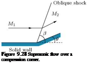
From studies on inviscid flows, we know that any streamline can be regarded as a solid boundary. In our present study, we treat the supersonic flow as inviscid and, therefore, here also the streamlines can be assumed as solid boundaries. Thus the oblique shock flow results, already described, can be used for solving practical problems like supersonic flow over a compression corner, as shown in Figure 9.28. For any given values of M1 and в, the values of M2 and в can be determined from oblique shock charts or table (oblique shock charts and table are given in the Appendix of Rathakrishnan (2010)).
 |
 |
|
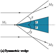
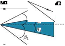
In a similar fashion, problems like supersonic flow over symmetrical and unsymmetrical wedges (Figure 9.29) and so on also can be solved with oblique shock relations, assuming the solid surfaces of the objects as streamlines in accordance with nonviscous (or inviscid) flow theory.
(b) Unsymmetrical wedge
Figure 9.29 Flow past (a) symmetrical and (b) unsymmetrical wedges.
Figure 9.30 Waves in a supersonic stream.
In Figure 9.29(b), the flow on each side of the wedge is determined only by the inclination of the surface on that side. If the shocks are attached to the nose, the upper and lower surfaces are independent and there is no influence of wedge on the flow upstream of the shock waves.
In our discussion on shock angle в and flow turning angle в, we have seen that when в decreases to zero, в decreases to the limiting value p giving rise to Mach waves in the supersonic flow field (see Figure 9.30(b)), which is given from Equation (9.168) as:
M2 sin2 p – 1 = 0 (9.171)
Also, the pressure, temperature and density jump across the shock (p2 — pi, T2 — T1 and p2 — p{) given by Equations (9.156)-(9.158) become zero. There is, in fact, no finite disturbance in the flow. The point P in Figure 9.30(b) may be any point in the flow field. Then the angle p is simply a characteristic angle associated with the Mach number M by the relation:
![]()
 |
(9.172)
This is called Mach angle-Mach number relation. These lines which may be drawn at any point in the flow field with inclination p are called Mach lines or Mach waves. It is essential to understand the difference between the Mach waves and Mach lines. Mach waves are the weakest isentropic waves in a supersonic flow field and the flow through them will experience only negligible changes of flow properties. Thus, a flow traversed by the Mach waves do not experience change of Mach number. Whereas the Mach lines, even though are weak isentropic waves will cause small but finite changes to the properties of a flow passing through them. In uniform supersonic flows, the Mach waves and Mach lines are linear and inclined at an angle given by p = sin-1 (1 /M). But in nonuniform supersonic flows the flow Mach number M varies from point to point and hence the Mach angle p, being a function of the flow Mach number, varies with M and the Mach lines are curved.
In the flow field at any point P (Figure 9.30(c)), there are always two lines which are inclined at angle p and intersect the streamline, as shown in Figure 9.30(c). In a three-dimensional flow, the Mach wave is in the form of a conical surface, with vertex at P. Thus, a two-dimensional flow of supersonic stream is always associated with two families of Mach lines. These are represented with plus and minus sign. In Figure 9.30(c), the Mach lines with ‘ + ’ sign run to the right of the streamline when viewed through the flow direction and those lines with “ — ” sign run to the left. These Mach lines which introduce an infinitesimal, but finite change to flow properties when a flow passes through them are also referred to
as characteristics, which are not physical unlike the Mach lines and Mach waves. But the mathematical concept of characteristics (taken as identical to the Mach lines), even though not physical forms the basis for the numerical method termed method of characteristics, used to design contoured nozzles to generate uniform and unidirectional supersonic flows.
At this stage it is essential to note the difference between the Mach waves, characteristics and expansion waves. Even though all these are isentropic waves, there is a distinct difference between them. Mach waves are weak isentropic waves across which the flow experiences insignificant change in its properties. Whereas, the expansion waves and characteristics are isentropic waves which introduce small, but finite property changes to a flow passing them. Thus, even though we loosely state that the Mach lines and Mach waves are isentropic waves in a supersonic flow, inclined at angle g to the freestream direction, in reality they are distinctly different. Mach waves are the weakest degeneration of isentropic waves to the limiting case of zero strength that a flow across which will not experience any change of property. Whereas, a Mach line is a weak isentropic wave in a supersonic flow field, causing small but finite change of properties to the flow passing through it.
The characteristic lines play an important role in the compression and expansion processes in the sense that it is only through these lines that it is possible to retard or accelerate a supersonic flow isentropically. Also, this concept will be employed in designing supersonic nozzles with Method of Characteristics.
It is seen from Equation (9.161) that for determining M2 the flow deflection angle в must be known. Further, for each value of shock angle в at a given M1 there is a corresponding flow turning angle в. Therefore, в can also be expressed as a unique function of M1 and в. From Figure 9.25, we have:
Vx1
tan в =— (9.163)
Vy V
tan^ – в) = —. (9.164)
Vy
Combining Equations (9.163) and (9.164), we get:
![]()
![]() tan^ – в) _ Vx2 VX1 .
tan^ – в) _ Vx2 VX1 .
Vx2 P_
Vx1 P2
Now, substituting for Pi/p2 from Equation (9.156), we get:
![]()
tan(^ — 9) (y — 1)Mj2 sin2 в + 2
tan в (y + 1)Mj sin2 в
Equation (9.166) is an implicit relation between 9 and в, for a given M1. With some trigonometric manipulation, this expression can be rewritten to show the dependence of 9 on Mach number Mj and shock angle в, as:
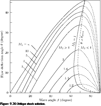 |
Equation (9.167) is called the 9-в-M relation. This relation is important for the analysis of oblique shocks. The expression on the right-hand side of Equation (9.167) becomes zero at в = n/2 and в = sin-1 (M-), which are the limiting values of в, defined in Equation (9.162). The deflection angle 9 is positive in this range and must therefore have a maximum value. The results obtained from Equation (9.167) are plotted in Figure 9.26, for y = 1.4. From the plot of 9-в-M (Figure 9.26) curves, the following observations can be made:
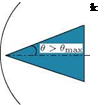
Figure 9.27 Detached shocks.
1. For any given supersonic Mach number M1, there is a maximum value of в. Therefore, at a given M1, if в > emax, then no solution is possible for a straight oblique shock wave. In such cases, the shock will be curved and detached, as shown in Figure 9.27.
2. When в < emax, there are two possible solutions, for each value of в and M, having two different wave angles. The larger value of в is called the strong shock solution and the smaller value of в is referred to as the weak shock solution. For strong shock solution, the flow behind the shock becomes subsonic. For weak shock solution, the flow behind the oblique shock remains supersonic, except for a small range of в slightly smaller than emax, the zone bounded by the M2 = 1 curve and в = emax curve shown in Figure 9.26.
3. If в = 0, then в = n/2, giving rise to a normal shock, or в decreases to the limiting value g, that is, shock disappears and only Mach waves prevail in the flow field. That is, when the flow turning angle в is zero, the following two solutions are possible for the shock angle в, for a given M1. (a) Either в = n/2 giving rise to a normal shock which does not cause any flow deflection, but would decelerate the flow to subsonic level, or (b) в = sin—1 (1 /M1) = g corresponding a Mach wave, which even though inclined to the upstream flow, would not cause any flow deflection, being the limiting case of the weakest isentropic wave for a given M1.
A very useful form of в-в-M relation can be obtained by rearranging Equation (9.166) in the following manner: Dividing the numerator and denominator of the right-hand side of Equation (9.166) by 2M2 sin2 в and solving, we obtain:
![]() Y + 1 tan (в — в) y — 1
Y + 1 tan (в — в) y — 1
Mj2 sin2 в 2 tan в
This can be simplified further to result in:
![]()
![]()
![]()
 |
|
 |
|
Y + 1 sin в sin в M2 sin2 в — 1 = M,2 .
1 в 2 1 cos (в — в)
For small deflection angles в, Equation (9.168) may be approximated as:
M2 sin2 в — 1 ^ M2 tan в] в.
If Mi is very large, then в ^ 1, but M1в » 1 and Equation (9.169) reduces to:
Y + 1
в = в.
 |
It is important to note that oblique shocks are essentially compression fronts across which the flow decelerates and the static pressure, static temperature and static density jump to higher values. If the deceleration is such that the Mach number behind the shock continues to be greater than unity, the shock is termed weak oblique shock. If the downstream Mach number becomes less than unity then the shock is called strong oblique shock. It is essential to note that only weak oblique shocks are usually formed in any practical flow and it calls for special arrangement to generate strong oblique shocks. One such situation where strong oblique shocks are generated with special arrangements is the engine intakes of supersonic flight vehicles, where the engine has provision to control its backpressure. When the backpressure is increased to an appropriate value, the oblique shock at the engine inlet would become a strong shock and decelerate the supersonic flow passing through it to subsonic level.
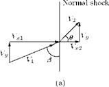
The flow through an oblique shock is illustrated in Figure 9.25(b). The flow through a normal shock (Figure 9.24(a)) has been modified to result in flow through an oblique shock, by superimposing a uniform velocity Vy (parallel to the normal shock) on the flow field of the normal shock (Figure 9.25(a)).
The resultant velocity upstream of the shock is V1 = Vx1 + Vy2 and is inclined at an angle в =
 |
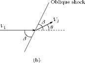 |
tan-1(Vx1/Vy) to the shock. This angle в is called shock angle. The velocity component Vx2 is always less than Vx1; therefore, the inclination of the flow ahead of the shock and after the shock are different. The inclination ahead is always more than that behind the shock wave, that is, the flow is turned suddenly at the shock. Because Vx1 is always more than Vx2, the turning of the flow is always towards the shock. The angle в by which the flow turns towards the shock is called flow deflection angle and is positive as shown in Figure 9.25. The rotation of the flow field in Figure 9.25(a) by an angle в results in the field shown in Figure 9.25(b), with V1 in the horizontal direction. The shock in that field inclined at an angle в to the incoming supersonic flow is called the oblique shock.
Figure 9.25 Flow through an oblique shock wave.
The relations between the flow parameters upstream and downstream of the flow field through the oblique shock, illustrated in Figure 9.25(b), can be obtained from the normal shock relations, since the superposition of uniform velocity Vy on the normal shock flow field in Figure 9.25(a) does not affect the flow parameters (e. g., static pressure) defined for normal shock. The only change is that in the present case the upstream Mach number is:
^ Resultant velocity V1
Speed of sound a1
The component of the upstream Mach number M1 normal to the shock wave is:
![]() Mn1 = M1 sin ft.
Mn1 = M1 sin ft.
Thus, replacement of M1 with M1 sin в in normal shock relations given by Equations (9.145), (9.148), (9.150) and (9.151) results in the following relations for an oblique shock:
![]() (y + 1) M2 sin2 в (y – 1)M2 sin2 в + 2
(y + 1) M2 sin2 в (y – 1)M2 sin2 в + 2
![]()
![]() (9.159)
(9.159)
The normal component of Mach number behind the shock Mn2 is given by:
From the geometry of the oblique shock flow field shown in Figure 9.25, it is seen that the Mach number behind the oblique shock, M2, is related to Mn2 by:
In the above equations, M2 = V2/a2 and Mn2 = Vx2/a2. The Mach number M2 after a shock can be
obtained by combining Equations (9.160) and (9.161).
Numerical values of the oblique shock relations for a perfect gas, with y = 1.4, are presented in graphical form. The same in tabular form is given in Table 3 of the Appendix of Rathakrishnan (2010) [1].
It is seen from the oblique shock relations given by Equations (9.155)-(9.159) that the ratio of thermodynamic variables depends only on the normal component of velocity (M1 sin в) ahead of the shock.
But, from normal shock analysis we know that this component must be supersonic, that is, Mi sin в > 1. This requirement imposes the restriction on the wave angle в that it cannot go below a limiting minimum value for any given M1. At this minimum limiting value of shock angle, the shock gets degenerated to an isentropic wave (also called Mach wave) across which the change of flow properties become negligibly small. Such a weak isentropic wave is termed Mach wave. The maximum value of в is that for a normal shock, в = n/2. Thus for a given initial Mach number M1, the possible range of wave angle is:
(9.162)
The limiting values of the wave angle in Equation (9.162) are of special significance. The limiting minimum value is sin-1 (M.) is the Mach angle x and the maximum value | corresponds to normal shock. Thus, the strongest wave possible in a given supersonic flow is the normal shock corresponding to the given M1. The weakest wave is the Mach wave corresponding to the given M1. It is essential to note that the shock wave formation is not mandatory in a supersonic flow. For example, in uniform supersonic streams such as the flow in a supersonic wind tunnel test-section, no shocks are formed when the test-section is empty, whereas the weakest limiting isentropic waves, namely the Mach waves, are always present in all supersonic flows. Even in the empty test-section of a supersonic tunnel the Mach waves are present. But we know that the waves in a supersonic flow are due to perturbations in the flow field. Therefore, it is natural to ask, “in an undisturbed uniform supersonic flow why should there be Mach waves present?” The answer to this question is the following. In a uniform supersonic flow such as that in a wind tunnel test-section, if the test-section walls are absolutely smooth there will not be any Mach wave present in the flow. However, absolute smooth surface is only a theoretical assumption. For instance, even surfaces such as that of a good quality Schlieren mirror has a finish of only about X/20, where X is the wavelength of light. Thus, any practical surface is with some roughness and not absolutely smooth. Therefore, any supersonic flow field generated by a practical device is bound to possess Mach waves. Indeed, the size of the gas molecules are enough to cause Mach wave generation. Therefore, even in a free supersonic flow without any solid confinement Mach waves will be present.
An important feature to be inferred here is that the Mach waves, like characteristics will be running to the left and right in the flow field. Because of this the Mach waves of opposite families prevailing in the flow field cross each other. But being the weakest degeneration of waves, the Mach waves would continue to propagate as linear waves even after passing through a number of Mach waves. In other words, the Mach waves would continue to be simple waves even after intersecting other Mach waves. Because of this nature of the Mach waves, a flow region traversed by the Mach waves is simple throughout.
The normal shock wave, a compression front normal to the flow direction. However, in a wide variety of physical situations, a compression wave inclined at an angle to the flow occurs. Such a wave is called an oblique shock. Indeed, all naturally occurring shocks in external flows are oblique.
In steady subsonic flows, we generally do not think in terms of wave motion. It is usually much simpler to view the motion from a frame of reference in which the body is stationary and the fluid flows over it. If the relative speed is supersonic, the disturbance waves cannot propagate ahead of the immediate vicinity of the body and the wave system travels with the body. Thus, in the reference frame in which the body is stationary, the wave system is also stationary; then the correspondence between the wave system and the flow field is direct.
The normal shock wave is a special case of oblique shock waves, with shock angle в = 90°. Also, it can be shown that superposition of a uniform velocity, which is normal to the upstream flow, on the flow field of the normal shock will result in a flow field through an oblique shock wave. This phenomenon will be employed later in this section to get the oblique shock relations. Oblique shocks are usually generated when a supersonic flow is turned into itself. The opposite of this, that is, when a supersonic flow is turned away from itself, results in the formation of an expansion fan. These two families of waves play a dominant role in all flow fields involving supersonic velocities. Typical flows with oblique shock and expansion fan are illustrated in Figure 9.24.
In Figure 9.24(a), the flow is deflected into itself by the oblique shock formed at the compression corner, to become parallel to the solid wall downstream of the corner. All the streamlines are deflected to the same angle в at the shock, resulting in uniform parallel flow downstream of shock. The angle в is referred to as Bow deflection angle. Across the shock wave, the Mach number decreases and the pressure, density and temperature increase. The corner which turns the flow into itself is called compression or concave corner. In contrast, in an expansion or convex corner, the flow is turned away from itself through
 |
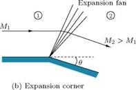 |
Figure 9.24 Supersonic flow over compression and expansion corners.
an expansion fan, as illustrated in Figure 9.24(b). All the streamlines are deflected to the same angle в after the expansion fan, resulting in uniform parallel flow downstream of the fan. Across the expansion wave, the Mach number increases and the pressure, density and temperature decrease. From Figure 9.24, it is seen that the flow turns suddenly across the shock and the turning is gradual across the expansion fan and hence all flow properties through the expansion fan change smoothly, with the exception of the wall streamline which changes suddenly.
Oblique shock and expansion waves prevail in two – and three-dimensional supersonic flows, in contrast to normal shock waves, which are one-dimensional. In this chapter, we shall focus our attention only on steady, two-dimensional (plane) supersonic flows.
There is no heat added to or taken away from the flow as it traverses a shock wave; that is, the flow process across the shock wave is adiabatic. Therefore, the total temperature remains the same ahead of and behind the wave:
![]() T02 = T01.
T02 = T01.
Now, it is important to note that Equation (9.152), valid for a perfect gas, is a special case of the more general result that the total enthalpy is constant across a normal shock, as given by Equation (9.135). For a stationary normal shock, the total enthalpy is always constant across the wave which, for calorically or thermally perfect gases, translates into a constant total temperature across the shock. However, for a chemically reacting gas, the total temperature is not constant across the shock. Also, if the shock wave is not stationary (that is, for a moving shock), neither the total enthalpy nor the total temperature are constant across the shock wave.
For an adiabatic process of a perfect gas, we have:
p01
S02 — S01 = R ln — .
p02
In the above equation, all the quantities are expressed as stagnation quantities. It is seen from the equation that the entropy varies only when there are losses in pressure. It is independent of velocity and hence there is nothing like stagnation entropy. Therefore, the entropy difference between states 1 and 2 is expressed, without any reference to the velocity level, as:
s2 – s = R ln —. (9.153)
P02
The exact expression for the ratio of total pressure may be obtained from Equations (9.153) and (9.151) as:
Equation (9.154) is an important and useful equation, since it connects the stagnation pressures on either side of a normal shock to flow Mach number ahead of the shock. Also, we can see the usefulness of Equation (9.154) from the application aspect. When a pitot probe is placed in a supersonic flow facing the flow, there would be a detached shock standing ahead of probe nose and, therefore, the probe measures the total pressure behind that detached shock. However, the portion of the shock ahead of a pitot probe mouth can be approximated as a normal shock. Thus, what a pitot probe facing a supersonic flow measures is the total pressure P02 behind a normal shock. Knowing the stagnation pressure ahead of the shock, which is the pressure in the reservoir, for isentropic flow up to the shock, we can determine the flow Mach number ahead of the shock with Equation (9.154).
For a calorically perfect gas, we have the equation of state, viz.
![]()
![]() p = pRT
p = pRT
and the enthalpy is given by:
h = cpT.
Equations (9.133) – (9.137) form a set of five equations with five unknowns: p2, p2, T2, V2 and h2. Hence, they can be solved algebraically. Inotherwords, Equations (9.133)-(9.135) are the general equations for a
 |
||
normal shock wave and for a perfect gas, it is possible to obtain explicit solutions in terms of Mach number, M, ahead of the shock using Equations (9.136) and (9.137) along with Equations (9.133)-(9.135), as follows: Dividing Equation (9.134) by Equation (9.133), we get:
Recalling that the speed of sound a = vYPTP, Equation (9.138) becomes:
Now, a2 and a2 in Equation (9.139) may be replaced with energy equation for a perfect gas as follows. By energy equation, we have:
 |
||
From the above relation, a12 and a22 can be expressed as:
Because the flow process across the shock wave is adiabatic, a* in the above relations for af and a2 has the same constant value.
 |
|
Substituting these relations into Equation (9.139), we get:
Dividing this equation by (V2 – Vj), we obtain:
Y + 1 2 Y – 1
———- a ———– — 1
2yV1 V2 2y
This may be solved to result in:
![]() (9.140)
(9.140)
which is called the Prandtl relation.
In terms of the speed ratio M* = V/a*, Equation (9.140) can be expressed as:
Equation (9.141) implies that the velocity change across a normal shock must be from supersonic to subsonic and vice versa. But, it will be shown later in this section that only the former is possible. Hence, the Mach number behind a normal shock is always subsonic. This is a general result, not limited just to a calorically perfect gas.
The relation between the characteristic Mach number M* and actual Mach number M is given [Equation (2.25) of Rathakrishnan (2010) [1]] as:
Using Equation (9.142) to replace M* and M* in Equation (9.141), we get:
Equation (9.143) shows that, for a perfect gas, the Mach number behind the shock is a function of only the Mach number M1 ahead of the shock. It also shows that when M1 = 1, M2 = 1. This is the case of an infinitely weak normal shock, which is identical to a Mach wave. It is essential to realize that the Mach waves in a supersonic flow field are at an angle p, = sin-1 (1/M), which is always less than n/2. In other words, a Mach wave is essentially an isentropic wave degenerated to a level that the flow across it will not experience any significant change of property. But, as Mi increases above 1, the normal shock becomes stronger and M2 becomes progressively less than 1, and in the limit, as M1 ^<X), M2 approaches a finite minimum value, M2 ^ V(Y — 1)/2y, which for air (at standard conditions), with y = 14 is 0’378.
The ratio of velocities may also be written as:
![]() V1 _ V22 _ V22
V1 _ V22 _ V22
V = vv = a*1
 |
|
Equations (9.142) and (9.144) are useful for the derivation of other normal shock relations. From Equation (9.133), we can write:
To obtain pressure relation, consider the momentum Equation (9.134):
P2 – P1 = P1V12 – P2V22
which, combined with Equation (9.133), gives:
P2 – P1 = P1 V1 (V1 – V2)
 V2
V2
Dividing throughout by p1, we get:
Now, recalling a = (yp1)/p1, we obtain:
![]() = M (■ – V)•
= M (■ – V)•
Substituting for V2/V1 from Equation (9.145), we get:
Equation (9.147) may also be written as:
The ratio (p2 — pi) /p1 = Ap/pi is called the shock strength.
The state equation p = pRT can be used to get the temperature ratio. With the state equation, we can write:
![]() T2 = f pi f pi T1 I pw IP2
T2 = f pi f pi T1 I pw IP2
 |
Substituting Equations (9.148) and (9.145) into Equation (9.149) and rearranging, we get:
or by a ^ 0), the perfect gas assumption is not valid. But, it is interesting to examine the variation of properties across the normal shock, for this limiting case. When M1 ^ ж, we find, for y = 1.4:
 = 0.378
6 P2
lim — = ж
M1^<x> p1
T2
lim — = ж.
М1^ж T1
At the other extreme case of an infinitely weak normal shock degenerating into a Mach wave, that is, at M1 = 1, Equations (9.143), (9.145), (9.148) and (9.150) yield M2 = p2/p1 = p2/p1 = T2/T1 = 1.That is, when Mi = 1, no finite changes occur across the wave.
Equation (9.151) justifies the statement we made earlier in this section: “from Prandtl equation, although it is possible for the flow to decelerate from supersonic to subsonic and vice versa across a normal shock wave, only the former is physically feasible.” From Equation (9.151), if M1 = 1, then As = 0; if M1 < 1, As < 0; and if M1 > 1, As > 0. Therefore, since it is necessary that As > 0 for a physically possible process, from the second law of thermodynamics, M1 must be greater than or equal to 1. When M1 is subsonic, the entropy across the wave decreases, which is impossible. Therefore, the only physically possible flow is M1 > 1, and from the above results we have M2 < 1, p2/p1 > 1, p2/p1 > 1 and T2/T1 > 1.
The changes in flow properties across the shock take place within a very short distance, of the order of 10—5 cm. Hence, the velocity and temperature gradients inside the shock structure are very large. These large gradients result in increase of entropy across the shock. Also, these gradients internal to the shock provide heat conduction and viscous dissipation that render the shock process internally irreversible.
In Section 2.13 of Chapter 2, we briefly discussed about the compression and expansion waves. Now, let us have a closer look at these waves and the flow process across them. Shock is a compression front across which the flow properties jump. Shock may also be described as compression front in a supersonic flow field and the flow process across the front results in an abrupt change in fluid properties. In other words, shock is a thin region where large gradients in temperature, pressure and velocity occur, and where the transport phenomena of momentum and energy are important. The thickness of the shocks is comparable to the mean free path of the gas molecules in the flow field.
9.19.1 Equations of Motion for a Normal Shock Wave
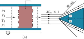 |
For a quantitative analysis of changes across a normal shock wave, let us consider an adiabatic, constant – area flow through a nonequilibrium region, as shown in Figure 9.23(a). Let sections 1 and 2 be sufficiently away from the non-equilibrium region so that we can define flow properties at these stations, as shown in Figure 9.23(a). Now we can write the equations of motion for the flow considered as follows:
By continuity
P1V1 = P2 V2. (9.133)
The momentum equation is
P1 + P1V2 = p2 + p2V|. (9.134)
The energy equation is
h1 + І V2 = h2 + 2 V2. (9.135)
Equations (9.133)-(9.135) are general – they apply to all gases. Also, there is no restriction on the size or details of the nonequilibrium region as long as the reference sections 1 and 2 are outside of it. The solution of these equations gives the relations that must exist between the flow parameters at these two sections.
Since there are no restrictions on the size or details of the nonequilibrium region, it may be idealized as a vanishingly thin region, as shown in Figure 9.23(b), across which the flow parameters jump. The control sections 1 and 2 may also be brought arbitrarily close to the thin region. Such a compression front across which the flow properties change suddenly is called a shock wave. Heat is neither added to nor taken away from the flow as it traverses the shock wave; hence the flow process across the shock wave is adiabatic.
In many text books shock is defined as a discontinuity. From our discussions above, the question obviously arises; is it possible to have a discontinuity in a continuum flow field of a real fluid? We should realize that the above consideration is only an idealization of the very high gradients of flow properties that actually occur in a shock wave, in the transition from state 1 to state 2. These large gradients produce viscous stress and heat transfer, that is, nonequilibrium conditions inside the shock. The processes taking place inside the shock wave itself are extremely complex, and cannot be studied on the basis of equilibrium thermodynamics. Temperature and velocity gradients inside the shock provide heat conduction and viscous dissipation that render the flow process inside the shock internally irreversible. In most practical applications, primary interest is not generally focused on the internal mechanism of the shock wave, but on the net changes in fluid properties taking place across the wave. However, there are situations where the detailed information about the flow mechanism inside the shock describing its structure is essential for studying practical problems. But since such conditions occur only in flow regimes like rarefied flow fields, it is not of any interest for the present study. Thus, shock is not a discontinuity but an active continuum compression front causing sudden changes to the flow properties.