Category THEORETICAL AERODYNAMICS

Moving Disturbance

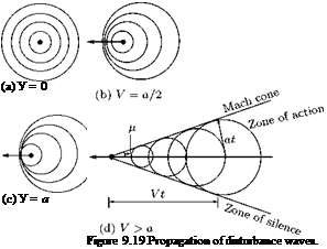
The presence of a small disturbance is felt throughout the field by means of disturbance waves traveling at the local velocity of sound relative to the medium. Let us examine the propagation of pressure disturbance created by a moving object shown in Figure 9.19. The propagation of disturbance waves created by an object moving with velocity V = 0, V = a/2, V = a and V > a is shown in Figures 9.19(a), (b), (c), (d), respectively. In a subsonic flow, the disturbance waves reach a stationary observer before the source of disturbance could reach him, as shown in Figures 9.19(a) and 9.19(b). But in supersonic flows it takes considerable amount of time for an observer to perceive the pressure disturbance, after the source has passed him. This is one of the fundamental differences between subsonic and supersonic flows. Therefore, in a subsonic flow the streamlines sense the presence of any obstacle in the flow field and adjust themselves well ahead of the obstacles and flow around it smoothly.

But in a supersonic flow, the streamlines feel the obstacle only when they hit it. The obstacle acts as a source and the streamlines deviate at the Mach cone as shown in Figure 9.19(d). That is in a supersonic flow the disturbance due to an obstacle is sudden and the flow behind the obstacle has to change abruptly.

Flow around a wedge shown in Figures 9.20(a) and 9.20(b) illustrate the smooth and abrupt change in flow direction for subsonic and supersonic flow, respectively. For < 1, the flow direction changes smoothly and the pressure decreases with acceleration. For Mx > 1, there is a sudden change in flow direction at the body and the pressure increases downstream of the shock.

(a) Subsonic flow

In Figure 9.19(d), it is shown that for supersonic motion of an object there is a well-defined conical zone in the flow field with the object located at the nose of the cone and the disturbance created by the moving object is confined only to the field included inside the cone. The flow field zone outside the cone does not even feel the disturbance. For this reason, von Karman termed the region inside the cone as the zone of action and the region outside the cone as the zone of silence. The lines at which the pressure disturbance is concentrated and which generate the cone are called Mach waves or Mach lines. The angle between the Mach line and the direction of motion of the body is called the Mach angle p. From Figure 9.19(d), we have:

Подпись: a V at

sin a

1 Vt

Подпись: (9.132)

that is:

From the disturbance waves propagation shown in Figure 9.19, we can infer the following features of the flow regimes:

• When the medium is incompressible (M = 0, Figure 9.19(a)) or when the speed of the moving dis­turbance is negligibly small compared to the local sound speed, the pressure pulse created by the disturbance spreads uniformly in all directions.

• When the disturbance source moves with a subsonic speed (M < 1, Figure 9.19(b)), the pressure disturbance is felt in all directions and at all points in space (neglecting viscous dissipation), but the pressure pattern is no longer symmetrical.

• For sonic velocity (M = 1, Figure 9.19(c)) the pressure pulse is at the boundary between subsonic and supersonic flow and the wave front is a plane.

• For supersonic speeds (M > 1, Figure 9.19(d)) the disturbance wave propagation phenomenon is totally different from those at subsonic speeds. All the pressure disturbances are included in a cone which has the disturbance source at its apex and the effect of the disturbance is not felt upstream of the disturbance source.

9.18.1 Small Disturbance
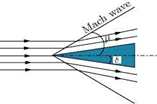
When the apex angle of wedge S is vanishingly small, the disturbances will be small and we can consider these disturbance waves to be identical to sound pulses. In such a case, the deviation of streamlines will be small and there will be infinitesimally small increase of pressure across the Mach cone shown in Figure 9.21.

9.18.2 Finite Disturbance

When the wedge angle S is finite the disturbances introduced are finite, then the wave is not called Mach wave but a shock or shock wave (see Figure 9.22). The angle of shock в is always smaller than the Mach angle. The deviation of the streamlines is finite and the pressure increase across a shock wave is finite.

The Prandtl-Glauert Rule

This is only an approximation and a greater simplification compared to Gothert’s rule. Here we need not effect any transformation in the z-direction at all. That means Equation (9.118) is no more necessary. Only Equation (9.116) which gives transformation to planform alone is necessary.

General considerations

The P-G rule introduces the concept of affinely related profiles in incompressible flow. Affinely related profiles are those for which, for example, the t/c ratio alone is different and a and f are same, that is, all the ordinates of the two profiles are related simply by a constant.

Подпись: t' t" Подпись: f " Подпись: a_ — = K a__ Подпись: (9.122)

Similarly, we can obtain affinely related profiles by changing a alone or f alone. In general, affinely related profiles as shown in Figure 9.17, can be obtained by:

Подпись: CP CP Подпись: Ci = CM = K CL CM 1 Подпись: (9.123)

We should effect only one of these parameters in Equation (9.122), in order to get affinely related profiles. For such profiles, it follows from theory and experiment that:

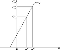
This can be thought as: if a for one wing is K times a for the second wing, then the CL, Cp and CM for the first wing should be correspondingly K times larger than those for the second wing. This is so because of the linearity of lift curve, shown in Figure 9.18.

These relationships hold only for the linear portion, because of the linearity involved in the theory.

Figure 9.18 Lift coefficient variation with angle of attack.


P-G Rule for Two-Dimensional Flow, using Equations (9.122) and (9.123)

We have to use Equation (9.122) with (9.118) and, (9.123) with (9.115), and set K = J11 — Ml | in Equations (9.122) and (9.123). What we have to prescribe now is our postulation for P-G rule versions I and II:

Version I:

MT = 0, for subsonic flow and, therefore,

Подпись: (9.124)t_ _ f _ a

t’ f a

where the prime refers to incompressible case. Version II:

MT = v/2 for supersonic flow and

t

_


1 — Ml


Therefore,

C^_CpC±_ t 1 1

CP"C CP" Kl" ^jT-MT

where the double prime refers to transformed profile.

Application to Wings

The general relation between the pressure coefficients of closely related wing profiles [Equation (9.115)] is:

1

1 – Mi


where “s” is the semi-span of wing. This transformed pressure coefficient ratio corresponds to Mi = 0 (Version I of P-G rule), for subsonic flow.

For Mi = V2 (supersonic flow), by Equation (9.125) of Version II, we get:

1


(9.126)


1 – m^ I
1

1 – Ml


(9.127)


By Gothert rule [Equation (9.115)], we have:

Подпись: CP CL CM 1 CP CL CM |1 - Mil a f t I |1 - M2|. a f t V (9.118)

By similarity rule for affinely related profiles in incompressible flow [Equation (9.122)], if:

t_ _ f_ _ <a_

t" f a"

then

c± = cl

ер cl


CL = *

cl 1


(9.123)


This is an empirical rule. For low speed flows, this can be explained with respect to a. But these equations are only approximate. Actually, for supersonic flow, CL does not depend on t at all. It depends only on f and a. We relate the given profile in compressible flow (unprimed) to the transformed profile (double primed) by:

t _ f _ a

t" f a"

With Equations (9.124a) and (9.118), we find that:

t’

t"


CL = 1 /11 – mi

t t"


or *1


1 – Ml


Then the aerodynamic coefficients of the given profile in compressible flow are related to those of the transformed profile (which has the same geometry) in incompressible flow or at Ml = V2 by:

Подпись: (9.125a)Cp _CL _ Cm _ 1

cp CL CM VIі – mi

because

C^ = c±Cl c c C"

cp cp cp


1

1 – Ml


1 — Ml I by Equations (9.115) and (9.123).


Application to Wings of Finite Span

The Gothert’s rule [Equation (9.115)] states that:

1


|i – ML


and by P-G rule, we have:

1


(9.126a)


1 – ML


Equation (9.126a) is only an approximate relation. Further:

(Cl) a, a,t/c, f/c (Cm ) A, a,t/c, f/c 1


(9.127a)


1 – Ml


The P-G rule is only approximate, but the Gothert’s rule, though exact, is very tedious, especially in three-dimensions, because here we have to transform the profile also. For P-G rule, only the planform has to be transformed.

From the P-G rule, for three-dimensional wings we obtain a similarity rule in the following way: if the relation:

CP = 6’Fi


(9.128)


for a wing is known at Ml = 0 and Ml = – Jl, then it follows for an arbitrary Mach number from Equations (9.116), (9.117) and (9.126), that:

Cp = L в. F2 ( X, A tan ф, Ах/11 — Ml |, c, Z


(9.129a)

(9.1297>)


-.F^X, A tan ф, Ау/11 — Ml| ^ -,F^X, A tan ф, Аyj |1 — M2|^


1 – Ml


where X is the taper ratio.

In Equation (9.129a): в means a or f/c or t/c.

In Equation (9.129Ь): в means a or f/c or t/c, but t/c only in subsonic flow. In Equation (9.129c): в means either t/c or f/c.

In Equations (9.128) and (9.129), ф is the angle of sweep for the wing.

Application to Bodies of Revolution

The application of P-G rule to bodies of revolution is similar to that for aerofoils (2-D), that is, no transformation of the body is necessary. The aerodynamic coefficients in compressible flow are the same as in incompressible flow or at Mx = V2. Hence, there is no Mach number effect at all and the results are same as those for slender body theory.

This contradicts the more exact Gothert rule. A closer examination shows that the P-G rule for bodies of revolution is valid only for very slender and extremely pointed (sharp-nosed) bodies. This theory is applied to rockets, very small aspect ratio wings, etc. Of course, wave drag is influenced by M even for slender bodies. We can use the results of incompressible flow for calculation of pressure distribution, etc.

From Figure 9.16(c), it is seen that for very small aspect ratio, the effect of Mach number is very small, and at A = 0 the Mach number effect vanishes.

9.17.6 The von Karman Rule for Transonic Flow Application to Wings

For M, x) = 1:

Cp = e2/3F5(X, A tan ф, Ав1/3, x/c, y/s)

(9.130a)

CL = e2/3F6(X, A tan ф, Ae1/3)

(9.130i>)

CD = e5/3F7(X, A tan ф, Ae1/3).

(9.130c)

Mathematically, these can be derived from the nonlinear differential equation (9.49). These laws are also approximately valid in the vicinity of MOT = 1. The main advantage of these similarity rules is that we have to investigate the influence of X, A tan ф, Ав1/3 only and not the influence of X, A, ф and в separately, which is very tedious. Thus, the rules are very important for experimental investigations.

Application to Bodies of Revolution

Подпись: C — C Cp = Cp Подпись: e'f Подпись: 2 Подпись: (9.131)

The pressure distribution of a body (unprimed) is related to the pressure distribution of an affinely related body (primed) at MOT = 1, by the relation:

where the subscript f stands for fuselage. This rule was derived by von Karman, but later on it was shown that a correction factor should be applied.

Application to Bodies of Revolution and Fuselage

The general, three-dimensional equations can be applied to these shapes. But it is more convenient to use polar coordinates for bodies of revolution and fuselage.

The potential equation in cylindrical polar coordinates, for incompressible flow is:

Подпись: (9.119)д2ф д2ф і дф і д2ф

дx2 + dr2 + r dr + r2 дв2


where x, r and в are the axial, radial and angular (circumferential) coordinates, respectively. For com­pressible flow, the equation is:

K1 = |1 – m2I.

From the streamline analogy:

Подпись: K2 =1

1 M2

Here again, as in Cartesian coordinates, transform the geometry and then calculate the aerodynamic coefficients for incompressible case and then the values for compressible case are given by Equation

(9.115). If f = 0, the only transformation required will be t/t = 1 / j 1 — M2 |. The variations of —^,

* HX

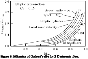
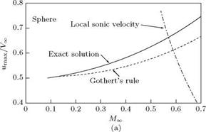
—^ j and l-mx / PfnoF with Mx are shown in Figures 9.16(a)-9.16(c), respectively.

da J c^=0 Ex V Ex / inc

In Figure 9.16(a), it is seen that beyond the chain line the results cannot be applied because once the speed of sound is reached locally, there will be shock somewhere and this is certainly a nonlinear effect. Though the plot is for a sphere, which is not a slender body, the results of Gothert rule are quite good (at Mx = 0.5, the error is only ~ 5%). For slender bodies, Gothert’s rule applies very well.

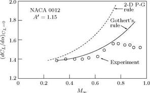
In Figure 9.16(b), the results for NACA 0012 profile with Aspect Ratio (A’) 1.15 are shown. For those Mach numbers for which locally speed of sound is not reached anywhere on the profile, Gothert’s rule agrees very well with experimental values. The Prandtl-Glauert rule for A = x shows that for large A’, the dCL/da obtained is much higher.

The three-dimensional relief effect is shown in Figure 9.16(c). For an infinitely long circular cylinder in a stream of velocity Ex, Mmax = Ух, but for a sphere Mmax = 0.5Ex. From the plot, the 3-D relief effect increases with increase in Mx. A slender body (small A’) introduces smaller perturbations, that is, the disturbances produced by wings are much more as compared to fuselage. This difference in disturbances

(b)


of wings and fuselage is greater at larger Mx. So, locally, speed of sound is reached first on wings and not on fuselage. That is, we should find out the critical Mach number for wings and not for the fuselage, since only the former is significant. The critical Mach number Mcr for the fuselage will be much higher than the Mcr for the wing.

Comparison of Two-Dimensional Symmetric Body and Axially Symmetric Body

For an axisymmetric body, in any cross-section the flow will be same. But this will not be so for a two­dimensional body. Also, at any cross-section, the disturbances produced by an axisymmetric body will be much smaller, that is, the acceleration of flow will be much less and hence the drop in the pressure coefficient Cp is much smaller compared to a two-dimensional body.

Application to Wings of Finite Span

Consider a wing planform transformation described here. Planform

Подпись: (9.116)Подпись:Taper ratio: к’ = к
Aspect ratio: A’ = A 11 — Ml |

Sweep angle: cot ф = cot 11 — Ml
A’ tan ф’ = A tan ф.

For subsonic flow, the transformation decreases A and for supersonic flow, the transformation increases A. Note that ф is sweep angle here.

Profile

The profile is given by the relations:

а=f=t=i i1 – M-1- (9118)

Thus, for wings (three-dimensional bodies), the Gothert rule is still more complicated; we have to trans­form not only the profile but also the planform, for each MOT. But this is the only reasonable method for wing analysis. In subsonic flow, these similarity rules are of great importance; but in supersonic flow, they are not that much important because even in two-dimensional subsonic flow, the elliptical equation is very difficult to solve, but in supersonic flow, the hyperbolic equation can be easily solved.

After making the transformations with Equations (9.116) and (9.118), find CL, CM, etc. for the incom­pressible case and then the corresponding coefficients for compressible case will be determined by the relations [Equation (9.115)]:

ca = cl = Cm= 1

Cp CL CM |1 — Ml

But it is tedious to find the variation of Cp, CL, CM with Mx because for each Mx we have to make the above transformations.

Gothert Rule

The aerodynamic coefficients of a body in three-dimensional compressible flow are obtained as follows. The geometry of the given body is transformed in such a way that its lateral and normal dimensions (both

in y and z directions) are multiplied by 11 — Ml |. If the flow is subsonic, compute the incompressible

flow about the transformed body; if the flow is supersonic, compute the field with Ml = [ї about the transformed body. The aerodynamic coefficients of the given body in given flow, follow from transformed flow with Equation (9.115).

Gothert rule can be applied to two-dimensional flows also (stated as version III of the Prandtl-Glauert rule).

It is exact in the framework of linear theory, whereas the Prandtl-Glauert rule is only approximate. For thicker bodies, when there is doubt about the accuracy with P-G rule, Gothert rule should be used even though it is tedious.

The coefficient of pressure is:

Cp = -2 —.

p V

V CO

Подпись: Cp = O CP Подпись: 2

The error involved in the pressure coefficients ratio is:

That is why the P-G rule, though approximate, can be used quite satisfactorily up to t/c = 15% (because the error is less). Gothert rule is still superior and is applicable not only to flow past bodies but also to flow through ducts where the diameter is small.

Three-Dimensional Flow: The Gothert Rule

9.17.1 The General Similarity Rule

The Prandtl-Glauert rule is approximate because it satisfies the boundary conditions only on the axis and not on the contour. But Gothert rule is exact and valid for both two-dimensional and three-dimensional bodies. The potential equation is (for < lor > 1):

For Mx < 1, the equation is elliptic in nature and for > 1, it is hyperbolic. Here also, we make transformation by which the transformed equation does not contain Mx explicitly any more. Let:

X = x, У = К1У, z’= K1Z, Ф = К2Ф.

With the above new variables, Equation (9.106) transforms into:

(1 – MXMv+ к2(фу, у,+ ф’„) = 0.

Mx vanishes from the above equation for:

K1 = j|1 – Ml. (9.107)

With Equation (9.107), the resulting potential flow equation for subsonic flow is:

ф’х’ X + ф’уу + фф’ = 0

and for supersonic flow:

ф’х’х’ – фУУ – фР’У = °.

Again, for subsonic flow, the equation is exactly the same as the Laplace equation. For supersonic flow, the equation is identical with the compressible flow equation [Equation (9.106)] with Mx = V2.

Now:

Подпись:, дф’ к дф K

дх’ дх

, _ дф’ _ K2 дф _ к2
v = ду = К дУ = К v

‘ дф’ К2 дф К2

w = ді = К1 д, = кw

с _ p – Рх _ _2 _____ 2_ дф

Р = 1 pVX = Vx= Vx дх

Подпись: and

ср = -2 —

p V"

with the assumption that Vx = Vy. This assumption really does not impose any restriction on the rule, because in supersonic flow, the velocity itself is not important (that is, V/a is more relevant than V). Introduction of Equation (9.108a) into Equation (9.110) results in:

Cp = —2K2—-

p 2 Vx

that is:

Hypersonic Similarity

The linear theory is not valid at high supersonic Mach numbers, since:

Подпись: u V V TO u

Подпись: For supersonic flow:

^ 1 is true only for supersonic flow, and ^ 1 for hypersonic flow.

Even slender bodies produce large disturbances in hypersonic flow. The original nonlinear equations have to be used for such flows. So, mathematically hypersonic flow is similar to transonic flow. In supersonic flow, slender bodies produce weak shocks and so these can be considered as Mach lines.[17] But in hypersonic flow, even slender bodies produce strong shocks and, therefore, in hypersonic flow we can no more deal with Mach lines and must deal with the actual shock waves. At high Mach numbers, the Mach angle a may be of the same order or less than the maximum deflection angle в of the body.

From these considerations, the similarity rule can be obtained for hypersonic flow. The Mach angle a is given by the relation:

sin Ц =

For the present case of flow shown in Figure 9.14:

1

sin а яь a = —— < в,

where в is the half angle of the wedge in the figure, that is, for hypersonic flow:

Мтов > 1. (9.99)

But in hypersonic flows even for small disturbances, there are shock lines and the angle of shock is always less than the angle of Mach line. Therefore, in reality the inequality in Equation (9.99), obtained with the approximation that Mach angle a is of the same order or less than the flow turning angle в, has to be modified since the shock angle is always less than a. In other words, it can be stated that Мтов is greater than some quantity K, whose numerical value can be less than unity also.

K = И^в > 0.5
K = ме,

Подпись: (9.100) (9.101)

where K is called the Hypersonic similarity parameter.

Example 9.2

For в = 10° (^ 0.174 radian), Mx = 4; the hypersonic similarity parameter K = М^в = 0.7. For в = 20° and M, x) = 2:

K = М^в ^ 0.7.

That is, for a wedge with half-angle 20°, Mx = 2 should be considered as hypersonic. This implies that M > 5 for hypersonic flow is only a crude limit. For в = 5° and MOT = 8:

K = M^в ^ 0.7.

Thus, a wedge with half-angle 5° in a flow with Mx = 8 produces shocks as strong as a wedge with half-angle 20° in a flow with MOT = 2.

Also, by Equation (9.98):

1 t 2a

» = *0 ± a = 2 tl1 ± – cl’ (!U02)

Подпись: K1 K2 Ki K2

Whenever M^в is the same for a number of bodies, the flow about them will be dynamically similar, that is, to investigate the hypersonic flow about a wedge with half-angle 5° and Mx = 8, we can use a supersonic tunnel with Mx = 2 and в = 20°. This is of paramount importance in testing; of course the two bodies should be affinely related (geometrically similar). Consider two models, 1 and 2:

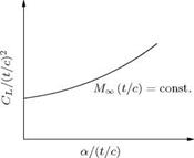
Figure 9.15 Variation of CL/(t/c)2 with a/(t/c).

This condition for dynamic similarity will be satisfied only when:

M<x>1 ^ c j = M<x,2 (c) •

That is, these two conditions should be satisfied for dynamic similarity, when there is geometric similarity:

c c = ( LcY M?"»( O-ttc)- (9Л03)

The total lift and drag coefficients are given by:

Cl =( C )! F,(«„( L).JL ) <9-104>

C„ = ( C )’ F, (m„ ( C ).tL ]. (9105)

Equations (9.103)—(9.105) give the functional dependence of various aerodynamic coefficients for hy­personic flow.

A plot like the one shown in Figure 9.15 gives the correct representation of the different parameters. This similarity rule is valid for axially symmetric bodies like rockets and missiles, also.

The transonic and hypersonic similarity rules discussed here are just a few glimpses, highlighting some of the vital features associated with them. Those who are looking for a deeper understanding of these problems should consult standard books on these topics.

Use of Karman Rule

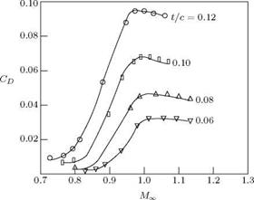
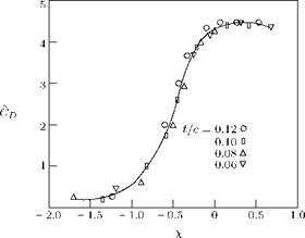
If we know the solution for one profile, we can find solutions for other affinely related profiles. For example, the NACA profiles designated by 8405, 8410, 8415 all have the same distribution, same nose radius etc.; only the absolute magnitude of t/c is different. This rule can be extended to transonic flow range also. From Figure 9.13, it is seen that in the transonic range, the aerodynamic coefficients change very quickly with Mach number, so that the proper values to be considered are not Mx, CL, CD and Cp; instead they are x, CL, C D and Cp.

Figure 9.13 The transonic similarity rule.


From the discussion made so far, we can make the following remarks:

1. For subsonic and supersonic flows, the governing equation (11 — M^ |) фхх + фгг = 0 is independent of y, so that the results from similarity rules can be applied to any gas; but for transonic flow, the potential equations are not independent of y. Therefore, the results have to be properly applied to different gases, with suitable correction for y, for example, a probe used for air in transonic range can be calibrated for steam.

2. For transonic flow:

t 2/3

c, ~ cL ~ (- )

Подпись: For subsonic flow:

c, ~ cL ~ (c )

Cp – CL

Подпись: c

Transonic flow is characterized by the occurrence of shock and boundary layer separation. This explains the steep increase in CD at transonic range. We should also recall that the shock should be sufficiently weak for small perturbation. For circular cylinder this theory cannot be applied, because the perturbations are not small.

The von Karman Rule for Transonic Flow

The potential Equation (9.49), for the present case of two-dimensional transonic flow, reduces to:

Vr (r + ^m!] m! ФФ


(1 — + фи


(9.97)


Equation (9.97) results in a form due to Sprieter (see also Liepmann and Roshko, 1963 [4]) for ML & 1, as:

2/3

[(Y + i)m!]1/3

(9.97b)

Подпись:

Подпись: t
Подпись: where

and Cp is the similarity pressure coefficient. It follows from Equation (9.97a) that the lift and drag coefficients are given by:

Equations (9.97a), (9.97c) and (9.97d) are valid for local as well as for total values. Sometimes, instead of thickness ratio t/c, ‘fineness ratio’ defined as in Figure 9.12 is used.

For the wedge shown in Figure 9.12:

1 t t

= tan во, – = 2 tan в0

2 c c

The ratio t/c is called the fineness ratio (at angle of attack = 0).

Подпись: (9.98)tan(eo±a) =tan [2C J1 ± t/c] ] .

where the ‘plus’ sign is for the upper surface and the ‘minus’ sign is for the lower surface. For finding the local values of Cp, CL and CD, we must use fineness ratio defined by these equations.

Analogy Version I

For this case of invariant profile in supersonic flow:

Подпись: K2 =1

л/МЇ-ї.

Compute the flow around the given body at MOT = v/2. For any other supersonic Mach number, the aerodynamics coefficients are given by:

Подпись: C^ = CL = CM_ C'P CL CM Подпись: (9.94a)1

уМЇ-ї ’

where Cp, Cl and Cm are at MOT = fl and Cp, Cl and Cm are at any other supersonic Mach number.

9.14.2.1 Analogy Version II

Here the requirement is to find a transformation for the profile, by which we can obtain a body, for which the governing equation is Equation (9.93a) with exactly the same pressure distribution as the actual body for which the governing equation is Equation (9.93b). For this:

K2 = 1.

The derivation of the above two results are left to the reader as an exercise. From the above results, we see that in supersonic flow Mx = fl plays the same role as Mx = 0 in subsonic flow.

Подпись: Cp CP Подпись: CL=CM CL CM Подпись: (9.94b)

For version II, we can write:

9.14.2.2 Analogy Version III: Gothert Rule

For any given body, at given Mach number MOT, find the transformed shape by using the rule:

7 = J = 7 = ^M^-T’ (995)

where a is the angle of attack, f and t are the camber and thickness of the given body, respectively. The primed quantities are for the transformed body and unprimed ones are for the actual body.

Подпись: C±=C±=C^ = 1 C'p CL CM M£ -1 Подпись: (9.96)

Compute the aerodynamic coefficients of the transformed body for MOT = V2. The aerodynamic coefficients of the given body at the given Mach number MOT follow from:

We can state the Gothert rule for subsonic and supersonic flows by using a modulus: 11 — M^ |.

From the discussion on similarity rules for compressible subsonic and supersonic flows, it is clear that, in subsonic flow, there is a ready made linearized solution for MOT = 0. Hence, for such cases we can use the Prandtl-Glauert rule. But for supersonic flow the linear theory equations are very simple and, therefore, we can conveniently use the Gothert rule.

Example 9.1

A given profile has, at MOT = 0.29, the following lift coefficients:

CL = 0.2 at a = 3°

Cl = — 0.1 at a = —2°,

where a is the angle of attack. Plot the relation showing dCL/da vs. MOT for the profile for values of MOT up to 1.0.

Solution

At Mx = 0.29:


0.2 + 0.1
3 + 2
3.438/rad


dCL

da


0.06/degree


1.094w/rad.


By the Prandtl-Glauert rule:

Therefore:

1.047w/radian.


For any other subsonic Mach number, by the Prandtl-Glauert rule:

dCL у da ) inc 1.047л

~da ~ уД-Mg ~ yr-ML.

Therefore, we

have the following variation:

M

0.1 0.2

0.3

0.4

0.5

0.6

0.7

0.8

0.9

dCL

da

1.05л 1.07л

1.10л

1.14л

1.21л

1.31л

1.46 л

1.74л

2.40л