Category Theoretical and Applied Aerodynamics

Induced Downwash in Manoeuvre

The simplest loading that will contribute to roll is mode 2, which is antisymmetric and does not contribute to lift as any mode An, n > 2. The mode 2 circulation and induced downwash are given by

r2[y(t)] = 2UbA2 sin2t sin 2t

wW2 [y (t)] = —2U A2 = —4U A2 cos t

sin t

Given that y(t) = -| cos t, 0 < t < n, the last relation reads

y

Ww2 (У) = 8UA2

b

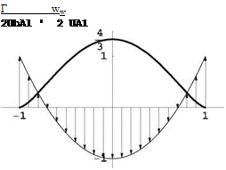
This is represented in Fig. 15.24.

15.6.2.3 Induced Drag in Manoeuvre

The induced drag is given by

Подпись:ideal ^1 + 2 ^^ = (CDt)ideal ^1 +

The increase in induced drag is 2%.

Induced Downwash in Manoeuvre Подпись: У

Fig. 15.24 Mode 2 loading for manoeuvre

Prandtl Lifting Line Theory

15.6.2.1 Downwash Evolution

A semi-infinite vortex sheet trailing a wing and contained in the (x, y) plane induces at a point in that plane a vertical component w(x, y) called downwash. Near the x-axis (- 2 < y < b), far upstream the effect of the wake decays and the downwash goes to zero. At the lifting line, ww(y) is the downwash induced by a semi-infinite vortex sheet. Far downstream, in the Trefftz plane, the downwash wT (y) results from an infinite vortex sheet. Because of the symmetry, the infinite vortex filaments induce velocities that are twice that of semi-infinite ones. As a result, wT (y) = 2ww(y).

15.6.2.2 Wing with Ideal Loading

As seen in class, the ideal loading of a wing for minimum induced drag is elliptic, i. e.

Theory shows that

Подпись: ww( y) Prandtl Lifting Line Theory

r0 = 2UbA1 = 2Ub (Cl’>cruise

2-D Inviscid, Linearized, Thin Airfoil Theories

15.6.1.1 Incompressible Flow (Mo = 0)

Airfoil Design

Consider a thin airfoil with parabolic camberline. The design requirements are the following:

• the take-off incidence is (Cl)t-o = 1.8

• the location of the center of pressure at take-off is Xe. = 0.4

The lift coefficient is (Cl)t-o = 2n(A0 + A-) = 1.8

The center of pressure location is (^), = Aq+Al—~ = 0.4

c }t-o 4(Aq+A!)

2-D Inviscid, Linearized, Thin Airfoil Theories

A profile with parabolic camberline has only two non-zero Fourier coefficients, Aq and Al. The two conditions read

The solution is Aq = 0.114 and Al = 0.344.

Подпись: -oThe take-off incidence is (a)t-o = Aq = 0.114rd = 6.5°. The profile relative camber is d = Al = 0.086.

For these conditions, the Selig 1223 can be used.

Lift Curve

The lift slope for all thin airfoils in inviscid, incompressible flow is <ddC – = 2n. The value of the Ci0, corresponding to a = 0 is Cl0 = nA1 = 1.08.

The sketch of the lift curve is presented in Fig. 15.20.

Equilibrium at Take-Off with Tail

If the center of gravity of the wing+tail configuration is located at Xl = 0.5 at take­off, the tail lift coefficient will be positive, Cl > 0 since the wing lift and aircraft weight create a nose up moment which must be balanced by the tail.

See Fig. 15.21.

15.6.1.2 Supersonic Flow (M0 > 1, в = ^M^ — 1)

A flat plate equips the fins of a missile cruising at Mach number M0 > 1ina uniform atmosphere. The chord of the airfoil is c.

Подпись: Fig. 15.21 Equilibrium at take-off 2-D Inviscid, Linearized, Thin Airfoil Theories

Fig. 15.20 Lift curve Ci (a)

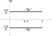
Fig. 15.22 Pressure coefficient distributions

2-D Inviscid, Linearized, Thin Airfoil TheoriesPressure Distribution and Global Coefficients

The pressure coefficients —C + and —C – versus x for this airfoil at a > 0 are simply ±2a and are plotted in Fig. 15.22.

From the derivations seen in class

a

Ci (a) — 4

2-D Inviscid, Linearized, Thin Airfoil Theories

P

2

Cd(a) — 4

P

Maximum Finess and Flow Features

With Cd including the viscous drag, the expression of the inverse of the finess, 1/f — Cd / Ci is

Подпись:1/f

Taking the derivative w. r.t Cl and setting the result to zero yield

24

(Cl )%t — p Cd0 Hence, the optimum Cd and Cl are found to be

Подпись:(Cd )opt — 2Cd0, (a)opt

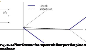
Подпись: z Fig. 15.23 Flow features for supersonic flow past flat plate at incidence

The sketch of the profile at incidence and of the remarkable waves is shown in Fig. 15.23.

Equilibrium of the Aggie Micro Flyer (AMF III)

15.5.3.1 Airplane Lift and Moment Curves

The equilibrium code calculated the lift and moment coefficients for the complete configuration at low incidences to be:

CL (a, tt) — 4.47a + 0.37tt + 1.11

Equilibrium of the Aggie Micro Flyer (AMF III)

См, о(а, tt) — -1.30a – 0.33tt – 0.28

corresponding to AR — 4.9. The main wing aspect ratio is ARm — bm/cm — 8. The difference is due to the wing+tail combination, whereby

Подпись:amCL m + atCLt

am + at

Therefore, the lift slope and the apparent aspect ratio is a weighted average of the wing and the tail aspect ratios.

Подпись: xac lref Подпись: dCM da dCL da Подпись: 1.3 447 Подпись: 0.29

As seen in class, the aerodynamic center xac location is given by

The aerodynamic center is located at xac = 0.29lref = 0.6 m.

15.5.3.2 Equilibrium Incidence

The center of gravity is located at xcg/lref = 0.21.

The static margin is SM = (xac – xcg)/lref = 0.08 = 8%.

The equilibrium incidence a(tt) satisfies the equilibrium equation

CM (aeq) + CL (aeq) = 0

lref

Подпись: aeq (tt) Подпись: — (0.33tt + 0.28) + 0.21(0.37tt + 1.11) -1.3 + 0.21(4.47) Подпись: 0.7tt - 0.13

Solving for aeq one obtains

15.5.3.3 Take-Off Conditions

Substituting the previous result in the lift equation provides the equation for the tail setting at take-off

CL, to = 2.0 = 4.47(-0.7tt – 0.13) + 0.37tt + 1.11

Solving for tt one finds tt, to = -0.533 rd = -31°.

The incidence at take-off is therefore ato = 0.24 rd = 14°.

The tail lift coefficient at take-off is CLt, to = 2.49ato + 2.61tt, to – 0.36 = -1.15. The lift force (in N) on the tail at take-off is Lt = 2 pU 2atCu = -12 N.

The force on the tail is down.

15.5.3.4 Extra Credit

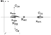
Free body diagram at take-off, see Fig. 15.19.

Подпись: Fig. 15.19 Free body diagram at take-off Подпись: z
Equilibrium of the Aggie Micro Flyer (AMF III) Подпись: x
Equilibrium of the Aggie Micro Flyer (AMF III)

Cw

15.6 Solution to Problem 6

Prandtl Lifting Line Theory

15.5.2.1 Origin of Induced Drag

Prandtl Lifting Line Theory Подпись: dS

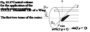
The remarkable feature, in the flow past a finite wing, is the existence of a vortex sheet, originating at the sharp trailing edge and trailing the wing to downstream infinity (Trefftz plane ST). In the proximity of the vortex sheet, which is made of vortex filaments parallel to the incoming flow, the flow field is perturbed. Far downstream, in the Trefftz plane, the pressure returns to the undisturbed static pressure, hence uT = 0 (since Cp = —2u/U). However, vT, wT = 0. An energy balance, applied to a large control volume, Fig. 15.17, shows that the energy in the Trefftz plane is larger that the incoming flow energy. Therefore, some positive work has been done to the fluid. This work is that of a thrust force which balances an equal and opposite drag force (induced drag). It can be shown that

Подпись: 2Гтах д 2Гтах nUb ’ 3 3nUb
Подпись: At
Подпись: correspond to

Подпись: Г [y(t)] = 2Ub p=0

Prandtl Lifting Line Theory

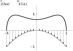
See the corresponding distribution of circulation and downwash, Fig. 15.18. There is no upwash, as one finds wT(y) = —8UA Ц – < 0.

Подпись: Г Ww 2UbAl ' 8 UA1

Fig. 15.18 Circulation and downwash

15.5.2.3 Induced Drag

Prandtl Lifting Line Theory Подпись: 4 3 (CDi)elliptic
Prandtl Lifting Line Theory Prandtl Lifting Line Theory

The induced drag can be written

showing a 33 % loss compared to the elliptic loading.

Prandtl Lifting Line Theory Подпись: — +СЮ

The induced drag due to two finite strength vortices is obtained when all the terms are added in the infinite series, i. e.

This is a diverging series.

2-D Inviscid, Linearized, Thin Airfoil Theories

15.5.1.1 Incompressible Flow (M0 = 0)

Definition

In 2-D, the following aerodynamic coefficients C/, Cm, o, and Cd are defined as
Подпись: z Fig. 15.13 Forces locations at take-off

L’ _ M _ D

Подпись:2 pU2c m’° 2 pU2c2’ d 2 pU2c

Подпись: Ci — 2na, 2-D Inviscid, Linearized, Thin Airfoil Theories Подпись: Cd — 0

The expressions for Cl(a), Cm, o (a) and Cd for a symmetric profile are

Suction Force

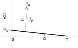
See the sketch of the flat plate at incidence and of the force due to pressure integration and the suction force on Fig. 15.14.

The suction force coefficient can be obtained since the resulting drag coefficient must be zero. Hence

Cs — F’j ^—pU2c^ — Ci sin a = Ci a — 2na2

The thickness distribution contributes to recuperating the suction force by allow­ing the boundary layer to remain attached at the rounded leading edge, thanks to the elimination of the singularity at the sharp trailing edge of the plate.

Center of Pressure

Definition: the center of pressure is the point about which the moment of the aero­dynamic forces is zero.

Подпись: Fig. 15.14 Flat plate at incidence—force due to pressure Fp, suction force Fs, resulting lift force L 2-D Inviscid, Linearized, Thin Airfoil Theories

As seen in class, the center of pressure for a symmetric profile is at the quarter – chord. This is easily shown by using the transfer of moment formula

xcp Cm, o 1

Подпись:

2-D Inviscid, Linearized, Thin Airfoil Theories Подпись: + XcpCl = 0 c

~ = cT = 4

For a symmetric profile, Cm, ac = 0, since the center of pressure coincides with the aerodynamic center (the formula for the value of Cm, ac is the same as that for

Cm, cp.

2-D Inviscid, Linearized, Thin Airfoil Theories 2-D Inviscid, Linearized, Thin Airfoil Theories 2-D Inviscid, Linearized, Thin Airfoil Theories

Computing Cm, o(a) from the Cm, ac, the change of moment formula gives

15.5.1.2 Supersonic Flow (Mo > 1, в = ^— 1)

A thin double wedge airfoil equips the fins of a missile cruising at Mach number M0 > 1 in a uniform atmosphere. The chord of the airfoil is c. The profile camber and thickness are:

d (x) = 0

Подпись:20x, 0 < x < c/2
2в(е – x), c/2 < x < c

with z±(x) = d(x) ± e(x)/2.

Pressure Distributions

C + and C – are the same at a = 0. One finds

C+ = C – = в в, 0 < x < c/2 C+ = C- = – вв, c/2 < x < c

See Fig. 15.15.

Lift Coefficient

The lift coefficient Ct (a) for all thin airfoils in supersonic flow is only a function of incidence

4

Ct (a) = a

P

Fig. 15.15 Pressure coefficients at a — 0

Drag Coefficient

2-D Inviscid, Linearized, Thin Airfoil Theories

The drag (wave drag) at zero incidence, (Cd)a=0, is

4 2 4 2

Cd (a) = в2 + a2

в в

Moment Coefficient

The zero incidence moment coefficient (Cm, o) 0 = 0 since it only depends on

camber.

2-D Inviscid, Linearized, Thin Airfoil Theories

Thus, the values of the coefficient Cm, o for the general case a = 0 is

Maximum Finess

The inverse of the finess, 1/f — Cd/Ci is

в2

1/f = + a

a

2-D Inviscid, Linearized, Thin Airfoil Theories

and the value of a that maximizes f satisfies

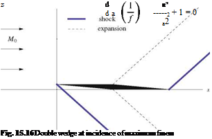
The solution is a = в (a =—в for negative lift). See Fig. 15.16 for remarkable waves (shocks, expansions).

Equilibrium of the Aggie Micro Flyer

The AMF has a span bm = 1m and a constant chord cxm = 0.192 m.

15.4.3.1 Main Wing

The wing aspect ratio is ARm = bm/S = bm/cxm = 5.2.

The theoretical formula gives dCLm/da = 2n/ (1 + 2/ARm) = 4.54 < 4.8701. This discrepancy is probably due to viscous effects seen in the 2-D viscous polar, in particular a laminar separation bubble near the leading edge on the lower surface that affects the leading edge geometry making the airfoil appear blunter when a < 0. The 2-D lift slope is found to be (dCi/da)a=0 = 7.5 > 2n.

15.4.3.2 Lift Curves

The general formula for the lift CL (a, tt) of the combination of the wing and tail of areas Am and At, and reference area Aref = Am + At is:

Подпись:AmCLm + AtCLt
Am + At

Here we get:

CL (a, tt) = 0.5573CLm + 0.4427CLt = 3.4374a + 1.5286tt + 0.2742

15.4.3.3 Moment Curve

The moment coefficient for the complete airplane is given by: CM, o(a, tt) = -1.378a – 1.268tt – 0.03492.

The equilibrium equation for the aerodynamic moment is given by:

xcg

CM, cg(aeq. tt) = CM, o(aeq. tt) + 7 CL (aeq. tt) = 0

lref

This gives CM, cg(aeq, tt) = -0.3248aeq – 0.7996tt + 0.0491 = 0.

Solving for aeq(tt) = —2.4618tt + 0.1512.

Application: horizontal flight at tt = 1.63° = 0.02845 rd ^ aeq = 0.0812 rd = 4.7°.

15.4.3.4 Take-Off Conditions

At CLm = 1.9, using the wing lift curve one finds (aeq)t_o = 0.2464rd = 14.1°.

The corresponding tail setting angle is given by the equilibrium equation to be (tt)t-o = -0.0387 rd = -2.216°. The tail lift curve gives a small positive lift Cu = 0.0076.

15.4.3.5 Extra Credit

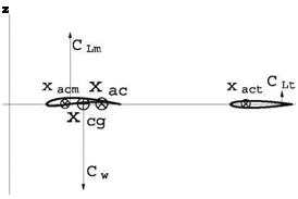
The AMF aerodynamic center is located at xac/lref = xcg/lref + SM = 0.3064 + 0.08 = 0.3864. The center of gravity is such that xacm/lref = 0.27 < xcg/lref = 0.3064 < xac/lref = 0.3864. At high take-off incidence, the center of pressure of the main wing is close to the aerodynamic center of the main wing, i. e. xcp/ lref = xacm/lref + є ~ 0.27 < xcg/lref = 0.3064. The main wing lift and the weight produce a nose up moment. Hence the tail must have a positive lift to counter that moment. See Fig. 15.13.

15.5 Solution to Problem 5

Prandtl Lifting Line Theory

15.4.2.1 Vortex Sheet

The vortex sheet is a stream surface originating at the sharp trailing edge of a finite wing. It is a surface of discontinuity of V. It has the following properties:

< u > = 0, no jump in u since pressure is continuous at the vortex sheet,

< w >= 0, no jump in w because the surface a zero thickness and the fluid is tangent to it (tangency condition)

< v >= 0, which can be related to the fact that the surface is made of vortex filaments of equation y = const., z = 0, 0 < x <ro.

15.4.2.2 Designing for Tip Vortices

Г[y(t)] = 2Ub{A1 sin t + A3 sin 3t}, where y(t) = -0.5b cos t, 0 < t < n.

Computing Г’ = (dГ/dt) / (dy/dt) shows that as, say, t ^ 0 the fraction is of the form 0/0. However, if dГ/dt ^ 0 faster than sin t a t, the result will be obtained.

dГ/dt = 2Ub{A1 cos t + 3A3 cos 3t}, thus, as t ^ 0 the necessary condition is A1 + 3A3 = 0. With this result, dГ/dt = 2UbA1{cos t – cos3t} a UbAtf2 as t ^ 0. The result is confirmed.

One finds A1 = (CL)t-o / (nAR) and A3 = – (CL)t-o / (3nAR).

The downwash is given by ww [y(t)] = —U {A1 +3 A3 sin3t / sin t }=-2UA1(1- 2 cos21). In terms of y this is ww(y) = -2UA1(1 – 2 (2y/b)2), a parabolic distri­bution. See Fig. 15.12.

The induced velocity ww is negative near the root, but there is upwash near the wing tips.

15.4.2.3 Induced Drag

The induced drag is given by Cm = nAR{A2 + 3A2} = (CDi)elliptic U + 332} = 4 (CDi )eiiiptic. There is a 33 % loss compared to the elliptic loading.

Подпись: Г ww 2UbAl ' 2 UA1 Fig. 15.12 Circulation and downwash for the wing with weak tip vortices
2-D Inviscid, Linearized, Thin Airfoil Theories

15.4.1.1 Incompressible Flow (M0 = 0)

Thickness Effect

In Thin Airfoil theory, the singularity distribution used to represent thickness are sources and sinks.

All the forces and moment coefficients are zero in the symmetric problem asso­ciated with thickness, C; and Cm, o are zero by symmetry, and Cd is zero because it is an inviscid flow theory.

The pressure coefficient Cp is affected by thickness, but the lift, drag and moment integrals are not.

Camber Effect

C; — 2n(a + 2dm) and Cm, o — – n(a + 4dm)/2.

Подпись: — 2n, C10 — 4ndm, da 2-D Inviscid, Linearized, Thin Airfoil Theories 2-D Inviscid, Linearized, Thin Airfoil Theories

The angle of zero lift is (a)Cl—0 — —2dm.

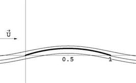
The flow past the mean camber line at a — 0 corresponds to the ideal angle of attack or angle of adaptation. The leading edge satisfies a Kutta-Joukowski condition. The flow is symmetric w. r.t x — c/2. See Fig. 15.9.

z/c

2-D Inviscid, Linearized, Thin Airfoil Theories

Fig. 15.9 Flow past thin parabolic plate at a = 0

Equilibrium About an Axis

At equilibrium the moment about the axis is zero, i. e. Cm, o = 0 ^ a = —4dm = -0.344 rd =-19.7°.

The equilibrium is stable because the slope of the moment about the axis, dCm, o/da, is negative.

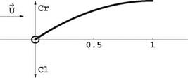
At equilibrium, the center ofpressure is at the nose, since xcp/c = – Cm, o/Cl = 0. See Fig. 15.10.

15.4.1.2 Supersonic Flow (M0 > 1, в = yjM( — 1)

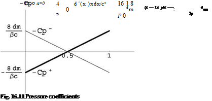
Pressure Distributions

C+ = ^(1 — 2х) and C— = (1 — 2х) at a = 0. See Fig. 15.11.

The corresponding lift coefficient is Cl = 0.

2-D Inviscid, Linearized, Thin Airfoil Theories

Fig. 15.1( Free body diagram of profile and hinge

2-D Inviscid, Linearized, Thin Airfoil Theories

Lift and Moment Coefficients

In the general case, C; = pa and Cm, o = -3pdm – pa for a = 0.

Equilibrium About an Axis

The moment about an arbitrary point D along the chord, Cm, D = Cm, o + =

(Cm, o)a=0 – ^1 – 2X^^ 2a. The condition for the equilibrium to be stable is that dCm, D/da < 0. This will be satisfied provided xD/c < 1/2.

The equilibrium incidence is

p. . 4

aeq — 2 Cm, o a=0 / (1 — 2xD/c) — —3dm/ (1 — 2xD/c)

aeq is independent of Mach number.

Glider Equilibrium

Away from high lift, a linear model of the glider in terms of the angle of incidence a (deg) and tail setting angle tt (deg) is given by:

CL (a, tt) = 0.1a + 0.01tt + 0.7
См,0(а, tt) = -0.02a – 0.01tt – 0.13

15.3.3.1 Definition

The aerodynamic center is the point about which the moment is independent of incidence.

15.3.3.2 Aerodynamic Center

As seen in class, the location of the aerodynamic center satisfies

^ ^ = 0.02/0.1 = 0.2

lref d a d a

hence xac = 0.3 m.

15.3.3.3 Moment at Aerodynamic Center

Using the transfer of moment formula one finds:

См, ac — См, о + ■— Cl — —0.02a — 0.01tt — 0.13 + -— (0.1a + 0.01tt + 0.7)

lref I ref

Using the result for xac this simplifies to:

См, ас — —0.008tt + 0.01

As expected, it is independent of a.

15.3.3.4 Moment at Center of Gravity

Using the transfer of moment formula one finds:
0.004a – 0.00841; – 0.018

Подпись: CM,cg — CM,acПодпись: IrefGlider EquilibriumThe airplane is statically stable because the slope dCfacg < 0.

15.3.3.5 Equilibrium

Подпись:At equilibrium, CM, cg —

a(tt) — 2.1t; 4.5

15.4 Solution to Problem 4