Our heavyweight helicopter equal in the world does not have
In Rostov started production of the most load-lifting rotary-wing car The Russian holding «Helicopt[...]

Everything about aircrafts and helicopters. News and events in aviation worldwide. Civil, transportation, military helicopters and airplanes.

Everything about aircrafts and helicopters. News and events in aviation worldwide. Civil, transportation, military helicopters and airplanes.

Everything about aircrafts and helicopters. News and events in aviation worldwide. Civil, transportation, military helicopters and airplanes.

Everything about aircrafts and helicopters. News and events in aviation worldwide. Civil, transportation, military helicopters and airplanes.


 |
Omniprobe is a marked improvement on the angular resolution of the multi-hole probes. With the use of 18 holes distributed on a spherical surface, streams can be evaluated from virtually any direction. The probe is able to detect velocity vector tilted up to 165° with respect to the probe.
These features allow measurement in highly inclined streams or even in reverse flow. The probe is useful in the exploration of wakes of bluff body, cars, wings, atmospheric wind.
Calibration is a fairly costly process that requires at least 7000 different tests. The diameter of the spherical head is about 10 mm. The Mach number can vary from 0.02 to 0.95.
To overcome the limitations on the maximum measured angle, seven – holes probes with a spherical or conical head are used (Figure 2.31). The angular resolution reaches 70° – r – 80°. The typical diameter of the measuring head is about 3 mm.
The process of calibration of such complex probes, as well as five-holes probes, consists in putting the probe in a known and uniform stream (known in terms of speed, direction of velocity, density, temperature, pressure) and in rotating the probe in a few thousand (e. g. 2000) different angles with respect to the stream and storing the readings of the various pressure taps. A map of calibration is obtained to find magnitude and direction of velocity on the basis of the pressures detected by the seven taps.
 |
Variants of the previous instrument are a cylinder with hemispherical head (Figure 2.29), a truncated pyramid (Figure 2.30) or a truncated cone. The advantage of these probes compared to the spherical probe is the elimination of separation.
 |
These probes measure the angles of pitch and yaw of the stream, the stagnation and the dynamic pressure; therefore provide sufficient data to fully calculate the fields of velocity and pressure. The maximum measurable angle is about 60°.
 |
Figure 2.30
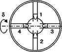
Another type of tool for subsonic 3D fields, shown in Figure 2.28, consists of a sphere supported on a stem parallel or orthogonal to the stream with 4 holes on the front located at 90° from each other and a central hole for the measurement of p0. The sensitivity of the instrument is about 0.08 per degree.
Figure 2.2 shows the theoretical and measured pressure around a sphere in laminar and turbulent flows. Assuming a potential flow maximum sensitivity is obtained at 42°, experimentally the maximum sensitivity is obtained around 50° and depends on the position of separation and thus on the Reynolds number. The transition point may move randomly producing asymmetry and indeterminate results. The maximum pitch angle detected is about 60°.
The presence of velocity gradients and the proximity of a wall restrict the use of this probe as they do for all probes with well-separated holes.
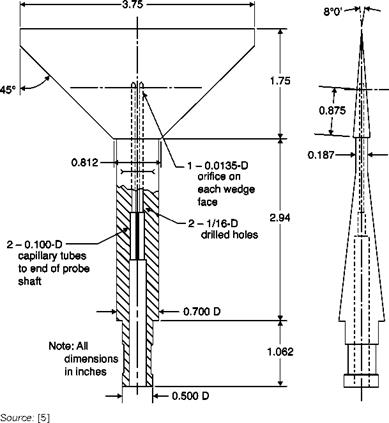
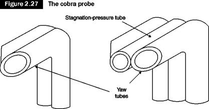
The previous probes have significant distances between the holes and therefore are not suitable for measurements in boundary layers. The cobra probe eliminates this problem because it consists of two tubes mounted side by side with entrances inclined to ±45° or ±60° (Figure 2.27). To reduce the response time, tapered tubes can be used so that the connecting tubes to the manometer have a larger diameter than the probe. These characteristics make it the best probe for the null reading method.
![Подпись: Figure 2.26 1 2 3 4 5 M Source: [5]](/img/3131/image117_1.gif) |
 |
Sensitivities of the cone and wedge probes as functions of the Mach number
Often a squared third central tube is provided for the measurement of p0, but in this case the distance between the holes increases. It should not be used to calculate the dynamic pressure and static pressure because the pressure difference between each of the side holes and the central one is only a relatively small fraction of the dynamic pressure. The probe is also used in supersonic flows and has a better sensitivity than the wedge for M > 2.
The wedge probes (Figure 2.25) have the advantage over the cylindrical ones of having higher critical Mach numbers (depending on the angle of opening) and of being much less sensitive to the position of the holes.
They are also suitable for supersonic flows. The influence of the Mach number on the sensitivity of some cones and a wedge can be seen from Figure 2.26; the sensitivity of a wedge of 8° turns out to be equivalent to that of a cone of 30° in the field 2 < M < 5. In the hypersonic regime,
|
A wedge probe
|
a conical configuration is almost universally used (with angles from 20° to 90°).
The probe consists of a cylinder perpendicular to the stream on which three holes are drilled, the central one for the measurement of stagnation pressure (Figure 2.23). The probe has a sensitivity of about 0.05 per degree.
As can be seen from Figure 2.2, the separation of the wake also changes the distribution of pressure in the upstream part of the cylinder and also in different ways according to the flow regime, laminar or turbulent. If the null reading method is used, that does not lead to errors because the situation is symmetrical about the axis, problems arise in the transitional regime in which there are oscillations of the wake and thus in the pressure.
 |
The sensitivity of the instrument depends on the position of the holes (Figure 2.24): at low Mach numbers, it is highest when the holes are placed at ±45°; for higher Mach numbers, the optimal angle increases, e. g. at M = 0.7 would be about ±70°. The critical Mach number, not to be exceeded, is 0.55.
 |
Effects of positioning of holes on a cylindrical probe at different Mach numbers
In a 3D version, a fourth hole on the cap that closes the cylinder is used to measure the pitch angle from the difference between measured pressure and stagnation pressure. This probe is small and is therefore used for measurements in tight spaces such as those typical of turbo machinery blades. Because of the distance between the holes, it is not very accurate in the presence of velocity gradients.
This probe consists of two Pitot tubes, inclined at ±45° with the axis of the probe (Figure 2.20). This probe is commonly used because it is easy
|
Claw probe; variation of sensitivity with Mach number
M |
to build but has some serious drawbacks: the structure is delicate and can easily be deformed with use; tube diameters, to reduce the distance, are small and show a slow response.
One version of the claw probe, to be used in the three-dimensional field, is sketched in Figure 2.21. It consists of four tubes which lie in pairs in two planes perpendicular to each other. There is also a version with five tubes with a central tube for the measurement of p0. Also the static pressure can be calculated through the use of appropriate empirical constants by combining the reading of the Pitot tube with that of one of the directional tubes. This probe suffers from the same limitations as the two-dimensional probe, and does not allow measurements in the vicinity of a wall.
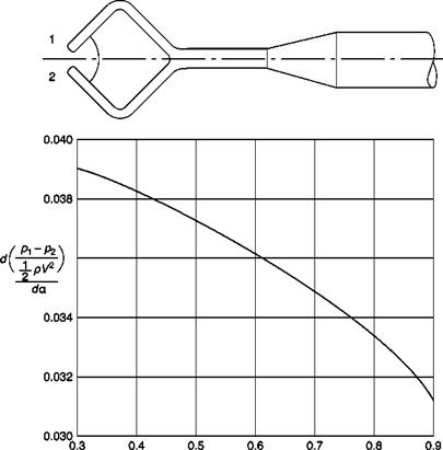
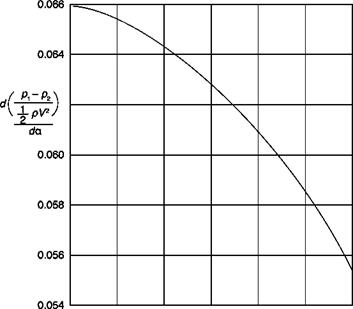
The Y probe (Figure 2.22) has a higher sensitivity but, due to the
 |
Ifb £~b
 Y probe; variation of sensitivity with Mach number
|
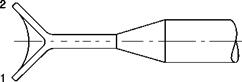
greater distance between the taps, is not suitable for measurements in the presence of gradients of velocity.
The probes used to measure flow speed, as we have seen, must be aligned with the direction of velocity and must have low sensitivity to the angle of attack. If the direction of the flow has to be known, it is mandatory to use probes with high sensitivity to the angle of attack (direction probes). Typically the shapes of these probes are simple bodies (sphere, cone, wedge, tube etc.). In all configurations, one or two pairs of taps, arranged symmetrically to the axis of the probe, are inclined on the direction of stream. With a pair of taps, measures of direction in 2D fields are obtained, in 3D fields, at least two pairs of taps are used.
For each body the aerodynamic sensitivity to the angle of attack is represented by the tangent to the curve Cp(a): the sensitivity of a Pitot tube (Figure 2.4) is negligible up to 10° and its maximum between 40°
|
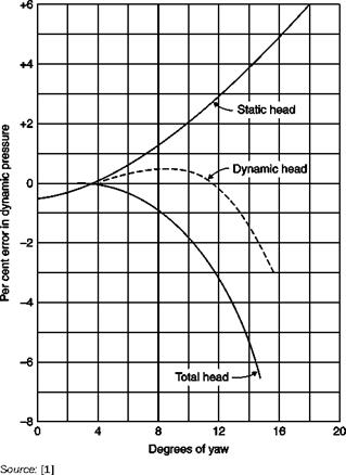
Performance of standard Pitot-static tube in yaw
|
and 60°. The sensitivities of cylinders and spheres show a similar behavior (Figure 2.2). Usually the pressure taps are positioned where the sensitivity is greatest, the only exception is the position where Cp = 0 used when, with the probe axis aligned with the speed, also the pressure pm must be measured. However, if precise measurements of pm are required, it is preferable to use a separate static tube.
Two different strategies able to measure the direction of velocity can be used:
1. The direction probe is rotated into the stream until the pressure difference between two opposite taps is zero (null reading method). The axis of the probe is then in the same direction of the stream in the limits of the accuracy of the instrument; construction errors can be
![]()
eliminated by repeating the test with the probe rotated at 180° and making an average between the two readings.
2. The probe is fixed in a reference direction (fixed method): the pressure difference between opposite taps is read and the corresponding angle between the axis of the probe and the direction of stream velocity is obtained from a calibration curve.
The first method is more immediate because it does not require calibration but has the disadvantage that the probe must be oriented with precision, which is particularly difficult if the probe is to be moved in a closed test chamber, or two angles in two orthogonal planes are to be measured (3D probes).
Calibration is often performed in a free jet flowing from a nozzle placed at the exit of a large stagnation chamber; the pressure difference between each pair of orifices divided by dynamic pressure is reported for each angle of the probe with the known velocity direction:
p-p = f(a)
Many types of probes are used, the choice is influenced by the Mach number of the stream, the type of flow (2D or 3D) and by considerations of robustness and ease of calibration. At low Mach numbers, the sensitivities of all the usual types of direction probes are of the same order, with values of d[(p2 – p1)/q]/da = 0.04 – r – 0.08 per degree. Using a suitable gage the direction of stream can therefore be determined with an approximation of 0.1°. The sensitivity decreases with increasing Mach number.
Measures of direction of velocity are rarely made in a uniform stream: there are almost always gradients of speed and therefore the errors due to gradients of stagnation pressure are present. If, on the other hand, the shear rate is strong, the measure of a direction probe is meaningless: even when the probe is aligned with the stream, there is a difference in pressure between the two taps because they see different speeds. These effects can be mitigated by minimizing the distance between the taps and using taps with small diameters.
A Pitot tube and a static tube can be combined into a single probe, called a Pitot-static tube; if the flow is incompressible the dynamic pressure and hence the speed can be directly measured from Equation (2.3).
The outline of a NASA standard probe is given in Figure 2.18: this probe consists of a Pitot tube inserted into a pipe with a hemispherical head in which static holes are positioned so that, for all sufficiently high Reynolds numbers, pressure disturbances induced by the head and those induced by the stem perpendicular to the axis of the pipe are below 0.5% and balanced. The performance of the probe at varying angles of incidence is shown in Figure 2.19.
Pitot-static tubes can be used without appreciable scale effects in the same range of Reynolds numbers of static tubes. In general, however, the head of the tube is quite blunt, and the effects of compressibility discussed
 |
Standard Pitot-static tube
above usually produce an error in static pressure at Mach numbers of the stream appreciably lower than 1. For this reason Pitot-static tubes are often not appropriate at high speeds where separate Pitot tubes and static tubes are preferred.