Category Aerodynamic measurements

Polarization

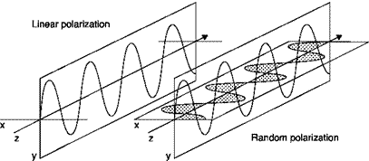
Lasers can be linearly or randomly polarized. The resonator of a laser creates standing waves of constant linear polarization. If special precautions are not taken, alternate longitudinal modes will have orthogonal polarization (Figure 4.6). Therefore, a laser is never really like a non-polarized thermal light source, it may be randomly polarized, i. e. it may issue a combination of orthogonally polarized radiation which, moreover, can vary over time. Introducing a Brewster angle window as a polarizing element within the laser cavity eliminates a state of polarization and produces a linearly polarized beam.

However, random polarization can be a problem if the beam interacts with polarizing elements or reflective surfaces and is detected by photo­electric sensors. The temporal fluctuation of polarization, polarization noise, gives rise to fluctuations in intensity and causes noise in the optical detector. In these applications, the use of a linearly polarized laser is recommended.

Temporal and spatial coherence

The interference between two beams can exist only if the frequency of the two beams remains constant in a certain period of time, this is indicated by the term temporal coherence. This condition is usually satisfied only if the two waves are generated by the same electronic transition in a particular atom. The time interval in which the characteristics remain constant, the time of coherence tco, is related to the frequency range of the emitted light by the equation

1 Я

t x = co Af fA

The coherence length £co = ctco = X2/AX limits the difference in path lengths of the two beams for which interference can still be generated. The light originated from a light source with thermal spontaneous emission, passed through a filter with an interferometric bandwidth, has a coherence length of the order of mm; for a laser, the coherence length is of the order of 1m (£co = c Af = 2L).

It must also be ensured that the light emitted from two different points of a source of finite dimensions (width d) and a certain divergence angle & can still interfere (spatial coherence). The answer is provided by the classical Young experiment: the necessary condition for the spatial coherence between the two beams is dsin© << X/ 2.

The high degree of spatial coherence of laser light is shown by the extreme parallelism of the beam of the laser. Because of the laws of diffraction, no laser beam is perfectly parallel: the slightest difference for a given diameter is obtained with a laser beam with a Gaussian profile (mode TEM00) for which the opening angle is in the order of mrad. In a laser beam that has an initial diameter of 0.8 mm and an angle of divergence of 1.1 mrad, the beam diameter is about 110 mm at a distance of 100 m.

Characteristics of laser light

The wavelengths of light emitted by the two main types of lasers are: 632.8 nm (red) for the HeNe laser and 514.5 nm (green) for the Argon laser. The power output of a standard HeNe laser ranges from 0.5 to 50 ml (the power supply is 10,000 times larger). Compared to conventional light sources, such as high pressure xenon or mercury lamps, the light output is surprisingly low, in fact, due to the collimation of the beam, even the smallest 0.5 mW laser has a brightness which is several orders of magnitude higher than that of conventional sources. A HeNe laser beam is visible and can be easily identified at a distance, even in daylight. Argon ion lasers have a light output in the order of W (and power supply in the order of kW) and require a circulation of cooling air or water.

The light from a conventional source cannot really be focused: a lens creates an image of the source in its focus according to the laws of geometrical optics and hence the power density of the image will be limited (Figure 4.5). A laser beam consists of parallel rays that are focused by a lens in a very small spot with high brightness: the relationship between the light power density in the spot and in the laser beam increases with the square of the inverse ratio of diameters; in a lens with a small focal length, this increase in light density can be of several orders of magnitude.

Focusing of an incoherent light source and of a laser beam

Principle of operation

A laser source is made with materials and construction techniques similar to those used for vacuum tubes (Figure 4.2). In it a current of plasma is generated since electrons are attracted by the anode and ions are attracted by the cathode. A capillary tube with a diameter of 1 mm is inserted into

the central part of the tube. To turn on the lasers, a starter is needed that allows the initiation of the arc that is then supported only by the power supply.

If the kinetic energy of electrons, depending on the difference of potential between the electrodes, is sufficient, one or more electrons of the atom move to a higher energy level in the collision with the ions, this phenomenon is called pumping. The electrons remain in this state for some time and then randomly and spontaneously return to a lower energy level, emitting energy as photons (spontaneous emission); the color, or wavelength, l, of this radiation depends on the difference of potential energy between the two levels.

Radiation, emitted in all directions, is neither coherent nor mono­chromatic, as a result of the superposition of electromagnetic waves with different wavelengths. To obtain laser light from this radiation, two small mirrors are needed, normal to the axis of the laser, at either end of the capillary tube; the photons directed along the axis of the capillary, and only those, are subject to repeated (infinite) reflections provoking another phenomenon called stimulated emission: when a photon hits an electron, this is moved to a higher energy level, it returns to its state of equilibrium with the emission of a photon exactly in the same direction as what it has invested. There is thus a multiplication of photons of the same type in the direction of the line joining the two mirrors in the capillary tube, and this leads to the formation of a thin, intense beam.

To obtain useful laser light outside, one of the two mirrors, the said transmitter, is not totally reflective and allows the escape of a small percentage of the light present in the cavity of the laser.

From the standpoint of the wave theory, the laser operation is linked to the fact that standing waves are generated in its optical cavity only if twice the length of the cavity is an integer multiple, m, of the wavelength: 2L = ml. Since m is large (order 106), there will always be many wavelengths 1m satisfying this criterion for which the light emitted from a laser will consist of a range of frequencies (f = c/l where c = speed of light) separated by Df = c/2L. These extremely narrow lines of which laser light is made are the longitudinal modes.

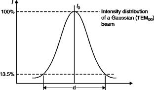
Since the mirrors and the capillary diameters are not zero, standing waves at small angles to the axis of the cavity can also exist. This gives rise to electric and magnetic transverse modes (TEMnm). Most of the laser operates in TEM00 mode, which has a Gaussian intensity profile (Figure 4.3) that provides the minimum divergence and can be focused on the smallest possible spot. Because the laser beam is not bounded by a sharp edge, its diameter is defined as that where the light intensity drops to 1/e2 (» 13.5%) of its peak value.

Подпись: Figure 4.3

Gaussian distribution of light intensity in a section of the laser beam

The emission of radiation can be within a broad spectral range, or a single wavelength can be optimized. Argon emits in a wide range of wavelengths ranging from ultraviolet to low infrared (Figure 4.4): this is

Подпись: Emission spectrum of argon Wavelength [nm]

Figure 4.4

because the atoms of an element have a limited number of excited states in which certain transitions from state to state, called allowed transitions, are more favored than others, called forbidden transitions. For a noble gas, a few dozen transitions are allowed: for argon, over 40% of the total power is emitted at a wavelength of 514.5 nm, which corresponds to the green color, more than 20% is emitted at 488 nm (blue), about 13% is emitted at 476.5 nm (purple).

In order to have emission of monochromatic light, it is necessary that the laser beam be purified from all radiation of wavelengths other than that required; this is achievable with the use of a prism that divides the rays allowing the choice of a particular color. With this system, much of the energy of total radiation will be lost; a more modern system, called a single-line operation, is equipped with a prism that selects the beam before it hits the total reflector, limiting the emission of photons at the desired wavelength.
The gas laser

The gas laser (light amplification by stimulated emission of radia­tion) emits a thin, intense beam of light, coherent over time and space, whose wavelengths depend on the gas used.

Lasers have numerous applications: sophisticated tools are com­mercially available that use lasers, which have often revolutionized measurement techniques such as engineering non-destructive testing, vibration analysis, measures of speed, quality control and surface rou­ghness, micron positioning, control of flatness and inclination, precision measurements at a distance of thicknesses, diameters and distances; lasers have also found applications in medicine, spectroscopy, information technology and graphics, printing techniques and display; with CD and DVD readers and writers, lasers have also entered the market for consumer products.

All these different applications are based on the specific characteristics of coherent beams of laser light; some use only the great brightness and collimation resulting from these properties, others use the more complex features of temporal and spatial coherence, e. g. in flow visualization. Laser sources have not only been successfully used in conventional optical methods but also have developed completely new methods such as holography and holographic interferometry.

Laser anemometry

Abstract: This chapter will address the measurement of velocity with non-intrusive optical methods based on a laser in a fluid stream seeded with submicron light-scattering particles.

Key words: laser Doppler anemometer (LDA), particle image velocimetry (PIV), two focus velocimeter (L2F).

4.1 Introduction

In the previous chapters, methods for measuring the velocity of a fluid involving the use of probes immersed in the stream have been described; the perturbations due to the probe itself can be reduced but not eliminated by using small probes. On the other hand, there are cases where it is quite impossible to introduce a probe into the stream: this may be due to high temperatures (flames, plasmas), to a too high dynamic pressure or to an abrasive or chemically aggressive fluid. In all these cases the use of an optical (and hence non-intrusive) method is mandatory.

The air and plenty of fluids, however, are transparent to light radiation, therefore the optical anemometers may be used only if the fluid is seeded with light-scattering particles. Because these particles act as indicators of stream velocity, even when it changes rapidly in time (turbulent flow), they must have a low inertia which implies a low density and/or a very small volume (diameter of the order of pm). Table 4.1 lists some types of particles used in various fluids and their maximum allowed diameter at two frequencies of speed fluctuation.

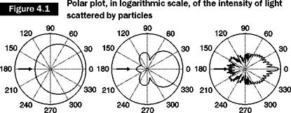
Since the particles have a diameter of the same order of magnitude as the wavelength of light, when they are hit by a light beam, they spread it in all directions (Mie’s theory): the back-scattered light (Figure 4.1) is hundreds of times smaller than the forward-scattered light.

Particle

Fluid

f = 1 kHz

f = 10 kHz

Polystyrene, polyamide, hollow glass spheres

Water

5-100

Water + glycerin (50% +50%)

Air

2-5

Silicone oil

Air

2.6

0.8

CM

О

і—

Air

1.3

0.4

MgO

Methane-air flame 1800 [K]

2.6

0.8

CM

о

І—

Oxygen plasma 2800 [K]

3.2

0.8

Table 4.1

Maximum diameter (mm) of tracer particles

Given the small size of the particles, only a small fraction of the total light is diffused, so only a laser can be used as a light source, as in it all the light output is concentrated in a beam approximately 1 mm in diameter.

The anemometers using a laser are:

■ the laser-Doppler anemometer (LDA): the speed of the particle is calculated from the difference between the frequency of the scattered light as perceived by an observer and that of the incident light;

■ the laser 2 focus (L2F) or laser transit anemometer (LTA): the speed is measured from the time the particle takes to travel the distance between two focused laser beams;

the PIV (particle image velocimetry): the velocity of many particles is measured from the distance that they trail in the time interval between two consecutive images of the test chamber.

dp = 0.2X dp = 1 .OX dp= 10X

Note: dp is the diameter of the particles, l the wavelength of the incident light.

ioo I

Intensity of turbulence in the direction of the average speed

The intensity of turbulence in the direction of the average speed is defined as

As we have seen, Equation (3.15), in a CTA, King’s law can be written as:

Подпись: 2EdE Подпись: в Подпись: dU

E1 = A + в4й = e2 + вій By differentiating this equation:

Подпись: = 4EV7 U = E - E

Interpreting E and U as the average values of voltage and speed and the differentials dE and dU as their rms values, a peculiar expression for the intensity of turbulence, may be found:

In order to measure the intensity of turbulence, it is only necessary to know the output voltage and the rms value of voltage, it is not necessary to know the calibration curve.

If the relationship E(U) is linearized, E = KU, to determine the intensity of turbulence, it is sufficient to make the ratio of the rms and the average value of voltage:

T = dU = dE 47

T U E E

Turbulence in the direction of the average speed

The component of turbulence in the direction of speed Vulcan be measured with a sensor perpendicular to the average speed. In the analog

anemometers, the corresponding voltage was measured with an rms voltmeter, based on the Joule effect, from the signal filtered to remove the DC component. In the modern computerized anemometers, the rms voltage value is obtained from

To obtain the rms value of velocity in linearized systems a factor of proportionality is simply applied. In non-linearized systems, conversion is accomplished by determining the slope of the calibration curve at the point of measurement. If the turbulence is large, an error of distortion is introduced in this way due to the uncertainty in choosing the proper curve slope.

Measurements in turbulent flows

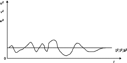
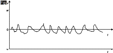
If the stream velocity varies in time, both in absolute value and in direction, turbulent regime, the situation can be summarized as in Figure 3.21:

U(t) = U+ u(t) V(t) = v(t) W(t) = w(t)

where the instantaneous value of the fluctuations of velocity components have been indicated with lower case letters and by U the average speed in a time interval much larger than the period of oscillations.

Since, obviously, the average values of fluctuations are identically zero,

u = v = w = 0

to have a measure of turbulence along the three axes it is necessary to make the square of the signal, thus eliminating the negative areas, make the average (Figure 3.22) and then extract the square root (the so-called root mean square value, rms)

vu W w

Turbulence intensity is defined as the ratio between the root of the arithmetic average of the rms values of the three components of the unsteady velocity and average speed:

u + v + w2

І

3

U

T =

Triaxial probe

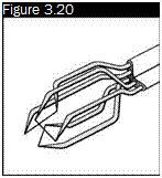
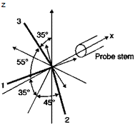
To determine the three-dimensional velocity vector, a set of three mutually perpendicular sensors, the triaxial probe of Figure 3.20, is needed to allow measurement in a cone of 70° around the axis of the probe.

Velocity components are calculated from the voltages measured at the three wires by using velocity curves obtained by calibration. The speeds on the three wires are obtained by equations:

k<u< + u2 + h1u3 = (l + k1 + h1 )cos 35.3°ucal1

k<u< + k2u2 + u3 = (l + k2 + h2)cos 35.3°ucal1

u<T h3 u2 + k3u3 = (1 + k3 + h3 )cos 35.3°uCal3

Putting, for simplicity, the values of h and k for all wires equal to those provided by the manufacturers, the velocity components in the direction of three sensors can be found from the equations:

u ^/-0.3676u2ali + 0.3747u2al2 + 0.3453u2al3

u2 = y]0.3453u2Ca/i – 0.3676uil2 + 0.3747ui/3

u3 =40.3747u2Cai + 0.3453u;al2 – 0.3676u2al3

Подпись: Figure 3.20 Подпись: z

Triaxial probe

Finally, the three components of the velocity vector in the coordinate system of the probe can be calculated from the equations:

u = u1 cos54.74° + u2 cos54.74° + u3 cos54.74°

v = – u1 cos 45° – u2 cosl35° + u3 cos 90°

w = – u1 cos114.09° – u2 cos114.09° – u3 cos35.26°