Category Aerodynamics for Engineering Students

The ratio of areas at different sections of the stream tube in isentropic flow

It is necessary to introduce the mass flow (m) and the equation of continuity, Eqn

(6.14) . Thus m = puA for the general section, i. e. without suffix. Introducing again the reservoir or stagnation conditions and using Eqn (6.1):

The ratio of areas at different sections of the stream tube in isentropic flow(6.21)

The ratio of areas at different sections of the stream tube in isentropic flow

Now the energy equation (6.17) gives the pressure ratio (6.18) above, which when referred to the appropriate sections of flow is rearranged to

Substituting VtPo/Po for ao and introducing both into Eqn (6.21), the equation of continuity gives

The ratio of areas at different sections of the stream tube in isentropic flow(6.22)

Now, if the general section be taken to be the particular section at the throat, where in general usage conditions are identified by an asterisk (*), the equation of continuity (6.22) becomes

The ratio of areas at different sections of the stream tube in isentropic flow(6.23)

But from Eqn (6.18b) the ratio p*/po has the explicit value

p* _ [7 + 11-7/(7-1)

Po [ 2

The ratio of areas at different sections of the stream tube in isentropic flow

converted to kinetic energy of linear motion. It follows from the definition that this state has zero pressure and zero temperature and thus is not practically attainable. Again applying the energy Eqn (6.17) between reservoir and ultimate conditions

7 Po_„T _<?

7-ІЙ) 2

The ratio of areas at different sections of the stream tube in isentropic flow Подпись: (6.27)

so the ultimate, or maximum possible, velocity

The ratio of areas at different sections of the stream tube in isentropic flow

Expressing the velocity as a ratio of the ultimate velocity and introducing the Mach number:

or

The ratio of areas at different sections of the stream tube in isentropic flow Подпись: (6.28)

and substituting Eqn (6.20a) for T/T0:

Pressure, density and temperature ratios along a streamline in isentropic flow

Pressure, density and temperature ratios along a streamline in isentropic flow
Подпись: «2 ~ «1 _ 7 (P Pi = 7 Pi 2 7 - 1 Pi P2) 7 - 1 P2

Occasionally, a further manipulation of Eqn (6.17) is of more use. Rearrangement gives successively

since it follows from the relationship (6.1) for isentropic processes that P1/P2 = W/92)7.

Pressure, density and temperature ratios along a streamline in isentropic flow Подпись: (6.18)
Подпись: Pi_ P2

Finally, with al = (1Р2ІР2) this equation can be rearranged to give,

Подпись: Po P Pressure, density and temperature ratios along a streamline in isentropic flow Подпись: (6.18a)

If conditions 1 refer to stagnation or reservoir conditions, щ = 0, p — po, the pressure ratio is

Po

P*

Подпись: '7+ 1 Подпись: 7/(7-!) Подпись: 1.89 for air flow Подпись: (6.18b)

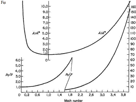
where the quantity without suffix refers to any point in the flow. This ratio is plotted on Fig. 6.2 over the Mach number range 0-4. More particularly, taking the ratio between the pressure in the reservoir and the throat, where M = M* = 1,

Pressure, density and temperature ratios along a streamline in isentropic flow Подпись: PdP

Note that this is the minimum pressure ratio that will permit sonic flow. A greater value is required to produce supersonic flow. The ratios of the other parameters follow from Eqns (6.18) and (6.2):

P2 P2j L 2

(6.19)

P L 2 J

(6.19a)

до Г7+ll1/(7-1)

’* = 7 г =1.58 for airflow P* L 2 J

(6.19b)

T (p\b 1)/7 7 – 1 «2 – »1

T2 pi) 2 a

(6.20)

^=i+7:V

T 2

(6.20a)

^ * = 1.2 for airflow T* 2

(6.20b)

Example 6.1 In streamline airflow near the upper surface of an aeroplane wing the velocity just outside the boundary layer changes from 257 km h-1 at a point A near the leading edge to 466kmh_1 at a point В to the rear of A. If the temperature at A is 281К calculate the temperature at B. Take 7 = 1.4. Find also the value of the local Mach number at the point B.

(LU)

Assume that the flow outside the boundary layer approximates closely to quasi-one-dimen­sional, isentropic flow.

Then

Подпись: TA 1 +Tb, , 7~ 1 ma ~ UB

«a

5 Подпись: aiaA

aK = 12Ay/l and ГА = 8 + 273 = 281К

да = 1215kmh_1

ы «А 257

"Л-^=Ш5“0212

— = = 0.385

aA 1215

^ = 1 + ~[0.2122 – 0.3852] = 0.979 = 1 – 0.021 ГА 5

Therefore

7b = 0.979 x 281 = 275 К = temperature at В яв = 72.4/275 = 1200 km IT1

Подпись: MB =Подпись: 1200466: = 0.386

Example 6.2 An aerofoil is tested in a high-speed wind tunnel at a Mach number of 0.7 and at a point on the upper surface the pressure drop is found to be numerically equal to twice the stagnation pressure of the undisturbed stream. Calculate from first principles the Mach number found just outside the boundary layer at the point concerned. Take 7 = 1.4. (LU)

Pressure, density and temperature ratios along a streamline in isentropic flow Pressure, density and temperature ratios along a streamline in isentropic flow Подпись: (і)

Let suffix cxi refer to the undisturbed stream. Then, from above,

Подпись: with the data given, Pressure, density and temperature ratios along a streamline in isentropic flow

and Eqn (i) gives

Isentropic one-dimensional flow

For many applications in aeronautics the viscous effects can be neglected to a good approximation and, moreover, no significant heat transfer occurs. Under these circum­stances the thermodynamic processes are termed adiabatic. Provided no other irrever­sible processes occur we can also assume that the entropy will remain unchanged, such processes are termed isentropic. We can, therefore, refer to isentropic flow. At this point it is convenient to recall the special relationships between the main thermo­dynamic and flow variables that hold when the flow processes are isentropic.

In Section 1.2.8 it was shown that for isentropic processes p = kp1 (Eqn (1.24)), where A: is a constant. When this relationship is combined with the equation of state for a perfect gas (see Eqn (1.12)), namely p/(pT) = R, where R is the gas constant, we can write the following relationships linking the variables at two different states (or stations) of an isentropic flow:

Pi _ Pi PT P2T2

Pf_P2 Pi Pi

(6.1

Y – (T’ =

T Vp,/

rp2(l~’)h

w

(6.2

From these it follows that

A useful, special, simplifed model flow is one-dimensional, or more precisely quasi – one-dimensional flow. This is an internal flow through ducts or passages having slowly varying cross-sections so that to a good approximation the flow is uniform at each cross-section and the flow variables only vary with. v in the streamwise direction. Despite the seemingly restrictive nature of these assumptions this is a very useful model flow with several important applications. It also provides a good way to learn about the fundamental features of compressible flow.

Isentropic one-dimensional flow Подпись: (6.3) (6.4) (6.5) (6.6) (6.7) (6.8) (6.9)

The equations of conservation and state for quasi-one-dimensional, adiabatic flow in differential form become

which, on dividing through by it1 A and using the identity M2 = tPja2 = рм2/(тр),* using Eqn (1.6d) for the speed of sound in isentropic flow becomes

Подпись: (6.10)Й=-7М2^

p u

Likewise the energy Eqn (6.5), with cpT — a2/(7 — 1) found by combining Eqns (1.15) and (1.6d), becomes

Подпись: (6.11)dT T

Then combining Eqns (6.7) and (6.8) to eliminate dр/р and substituting for dр/р and dT/T gives

(6.12)

* M is the symbol for the Mach number, that is defined as the ratio of the flow speed to the speed of sound at a point in a fluid flow and is named after the Austrian physicist Ernst Mach. The Mach number of an aeroplane in flight is the ratio of the flight speed to the speed of sound in the surrounding atmosphere (see also Section 1.4.2).

Equation (6.12) indicates the way in which the cross-sectional area of the stream tube must change to produce a change in velocity for a given mass flow. It will be noted that a change of sign occurs at M = 1.

For subsonic flow <L4 must be negative for an increase, i. e. a positive change, in velocity. At M = 1, dA is zero and a throat appears in the tube. For acceleration to supersonic flow a positive change in area is required, that is, the tube diverges from the point of minimum cross-sectional area.

Eqn (6.12) indicates that a stream tube along which gas speeds up from subsonic to supersonic velocity must have a converging-diverging shape. For the reverse process, the one of slowing down, a similar change in tube area is theoretically required but such a deceleration from supersonic flow is not possible in practice.

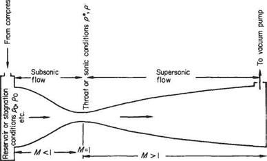
Other factors also control the flow in the tube and a simple convergence is not the only condition required. To investigate the change of other parameters along the tube it is convenient to consider the model flow shown in Fig. 6.1. In this model the air expands from a high-pressure reservoir (where the conditions may be identified by suffix 0), to a low-pressure reservoir, through a constriction, or throat, in a con­vergent-divergent tube. Denoting conditions at two separate points along the tube by suffices 1 and 2, respectively, the equations of state, continuity, motion and energy become

Подпись: (6.13)Подпись: (6.14)Pi Pi

PT P2T2

ріщАі = p2U2A2

piufA 1 – P2i^2A2+piAi – p2A2+{pi+P2){A2~A{) =0 (6.15)

Isentropic one-dimensional flow

Isentropic one-dimensional flow Подпись: u <D *
Isentropic one-dimensional flow

(6.16)

The last of these equations, on taking account of the various ways in which the acoustic speed can be

Compressible flow

Подпись: 6.1In previous chapters the study of aerodynamics has been almost exclusively restricted to incompressible flow. This theoretical model is really only suitable for the aero­dynamics of low-speed flight and similar applications. For incompressible flow the air density and temperature are assumed to be invariant throughout the flow Field. But as flight speeds rise, greater pressure changes are generated, leading to the compression of fluid elements, causing in turn a rise in internal energy and, in consequence, temperature. The resulting variation of these flow variables throughout the flow Field makes the results obtained from incompressible flow theory less and less accurate as flow speeds rise. For example, in Section 2.3.4 we showed how use of the incompressibility assumption led to errors in estimating the stagnation-pressure coefFicient of 2% at M = 0.3, rising to 6% at M = 0.5, and 28% at M = l.

But these errors in estimating pressures and other flow variables are not the most important disadvantage of using the incompressible flow model. Far more signiFicant is the marked qualitative changes to the flow Field that take place when the local flow speed exceeds the speed of sound. The formation of shock waves is a particularly important phenomenon and is a consequence of the propagation of sound through the air. In incompressible flow the fluid elements are not permitted to change in volume as they pass through the flow Field. And, since sound waves propagate by alternately compressing and expanding the medium (see Section 1.2.7), this is tanta­mount to assuming an inFinite speed of sound. This has important consequences when a body like a wing moves through the air otherwise at rest (or, equivalently, a uniform flow of air approaches the body). The presence of the body is signalled by sound waves propagating in all directions. If the speed of sound is inFinite the presence of the body is instantly propagated to the farthest extent of the flow Field and the flow instantly begins to adjust to the presence of the body.

The consequences of a Finite speed of sound for the flow Field are illustrated in Fig. 6.11(p.308). Figure 6.11b depicts the wave pattern generated when a source of disturbances (e. g. part of a wing) moves at subsonic speed into still air. It can be seen that the wave fronts are closer together in the direction of flight. But, otherwise, the flow field is qualitatively little different from the one (analogous to incompressible flow) correspond­ing to the stationary source shown in Fig. 6.1 la. In both cases the sound waves eventually reach all parts of the flow field (instantly in the case of incompressible flow). Contrast this with the case, depicted in Fig. 6.11c, of a source moving at supersonic speed. Now the waves propagating in the forward direction line up to make planar wave fronts. The flow Field remains undisturbed outside the regions reached by these planar wave fronts, and waves no longer propagate to all parts of the flow field. These planar wave fronts are formed from a superposition of many sound waves and are therefore much stronger than an individual sound wave. In many cases they correspond to shock waves, across which the flow variables change almost discontinuously. At supersonic speeds the flow Field is fundamentally wavelike in character, meaning that information is propagated from one part of the flow Field to another along wave fronts. Whereas in subsonic flow fields, which are not wavelike in character, information is propagated to all parts of the flow Field.

This wavelike character of supersonic flow fields makes them qualitiatively different from the low-speed flow Fields studied in previous chapters. Furthermore, the existence of shock waves brings about additional drag and many other undesirable changes from the viewpoint of wing aerodynamics. As a consequence, the effects of flow compressi­bility has a strong influence on wing design for high-speed flight even at subsonic flight speeds. It might at First be assumed that shock waves only affect wing aerodynamics at
supersonic flight speeds. This is not so. It should be recalled that the local flow speeds near the point of minimum pressure over a wing are substantially greater than the free – stream flow speed. The local flow speed first reaches the speed of sound at a free-stream flow speed termed the critical flow speed. So, at flight speeds above critical, regions of supersonic flow appear over the wing, and shock waves are generated. This leads to wave drag and other undesirable effects. It is to postpone the onset of these effects that swept-back wings are used for high-speed subsonic aircraft. It is also worth pointing out that typically for such aircraft, wave drag contributes 20 to 30% of the total.

In recent decades great advances have been made in obtaining computational solutions of the equations of motion for compressible flow. This gives the design engineer much greater freedom to explore a wide range of possible configurations. It might also be thought that the ready availability of such computational solutions makes a knowledge of approximate analytical solutions unnecessary. Up to a point there is some truth in this view. There is certainly no longer any need to learn complex and involved methods of approximation. Nevertheless, approximate analytical methods will continue to be of great value. First and foremost, the study of relatively simple model flows, such as the one-dimensional flows described in Sections 6.2 and 6.3, enables the essential flow physics to be properly understood. In addition, these relatively simple approaches offer approxi­mate methods that can be used to give reasonable estimates within a few minutes. They also offer a valuable way of checking the reliability of computer-generated solutions.

Preamble

Hitherto in this volume the study of aerodynamics has almost exclusively been restricted to incompressible flow. This is really only suitable for the aero­dynamics of low-speed flight and similar applications. For incompressible flow the density and temperature of the fluid are assumed invariant throughout the flow field. As the flow speeds rise the changes in pressure become greater, leading to the compression of fluid elements, causing in turn the internal energy, and therefore the temperature, to rise. The generation and transfer of heat due to viscous effects and heat conduction are also significant in the boundary layer. But these and other viscous effects are not considered in this chapter.

The chapter begins with the study of (quasi-) one-dimensional flow, This is an approximate approach that is suitable for flows through ducts and nozzles when the changes in the cross-sectional area are gradual. Under this circumstance the flow variables can be assumed uniform across a cross-section so that they only vary in the streamwise direction. Despite its apparently restrictive nature one­dimensional flow theory is applicable to a wide range of practical problems. It also serves as a good introduction to the concepts and phenomena of compressible flow, such as the development of shock waves when the air is accelerated through and beyond the speed of sound.

The chapter continues with a description of the formation of Mach and shock waves in two-dimensional flow. An important application of this theory is the study of wing aerodynamics. The nature of the flow around wings is greatly affected when the local flow speed exceeds the speed of sound. The flight speed at which this first occurs is called the critical Mach number and methods of estimating this quantity for specified wing sections are demonstrated. The (inviscid) equations of motion governing high-speed flows change their character so that their solutions become wavelike when the local Mach number exceeds unity. The behaviour of the Mach and shock waves in two-dimensional flow is described in some detail. In general, the equations of motion are non­linear in form and not amenable to analytical solution. Special approximate approaches exist for pure subsonic or supersonic flows. For example, the assumption of small perturbations to the freestream flow can be exploited to obtain approximate analytical solutions for both subsonic and supersonic flows around wings. Other approximate methods are also explored. The chapter closes with a short description of compressible flow around wings of finite span.

Computational (panel) methods for wings

The application of the panel method described in Sections 3.5 and 4.10 above, to whole aircraft leads to additional problems and complexities. For example, it can be difficult to define the trailing edge precisely at the wing-tips and roots. In some more unconventional lifting-body configurations there may well be more widespread difficulties in identifying a trailing edge for the purposes of applying the Kutta condition. In most conventional aircraft configurations, however, it is a relatively straightforward matter to divide the aircraft into lifting and non-lifting portions – see Fig. 5.46. This allows most of the difficulties to be readily overcome and the computation of whole-aircraft aerodynamics is now routine in the aircraft industry.

In Section 4.10, the bound vorticity was modelled by means of either internal or surface vortex panels, see Fig. 4.22. Analogous methods have been used for the three­dimensional wings. There are, however, certain difficulties in using vortex panels. For example, it can often be difficult to avoid violating Helmholtz’s theorem (see Section 5.2.1) when constructing vortex panelling. For this and other reasons most modern methods are based on source and doublet distributions. Such methods have a firm theoretical basis since Eqn (3.89b) can be generalized to lifting flows to read

Подпись: WingПодпись: WakeComputational (panel) methods for wings(5.81)

where n denotes the local normal to the surface and a and ц are the source and doublet strengths respectively.
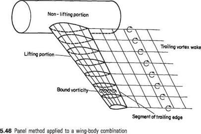
Fig


Computational (panel) methods for wings

For a given application there is no unique mix of sources and doublets. For many methods[28] in common use each panel of the lifting surface is assigned a distribution of constant-strength sources. The doublet distribution must now be such that it provides one additional independent parameter for each segment of the trailing edge. Once the doublet strength is known at the trailing edge then the doublet strength on the panels comprising the trailing vortidty is determined. The initially unknown doublet strength at the trailing edge segments represents the spanwise load distribution of the wing. With this arrangement each chordwise segment of wing comprises N (say) panels and 1 trailing-edge segment. There are therefore N unknown source strengths and one unknown doublet parameter. Thus for each chordwise segment the N + 1 unknowns are determined by satisfying the N zero-normal-velocity conditions at the collocation points of the panels on the wing, plus the Kutta condition.

As in Section 4.10 the Kutta condition may be implemented either by adding an additional panel at the trailing edge or by requiring that the pressure be the same for the upper and lower panels defining the trailing edge – see Fig. 4.23. The former method is much less accurate since in the three-dimensional case the streamline leaving the trailing edge does not, in general, follow the bisector of the trailing edge. On the other hand, in the three-dimensional case equating the pressures on the two trailing-edge panels leads to a nonlinear system of equations because the pressure is related by Bernoulli equation to the square of the velocity. Nevertheless this method is still to be preferred if computational inaccuracy is to be avoided.

Exercises

1 An aeroplane weighing 73.6 kN has elliptic wings 15.23 m in span. For a speed of 90 m/s in straight and level flight at low altitude find (a) the induced drag; (b) the circulation around sections halfway along the wings. (Answer: 1.37 kN, 44m2/s)

2 A glider has wings of elliptical planform of aspect ratio 6. The total drag is given by CD = 0.02 + 0.06C|. Find the change in minimum angle of glide if the aspect ratio is increased to 10.

3 Discuss the statement that minimum induced drag of a wing is associated with elliptic loading, and plot a curve of induced drag coefficient against lift coefficient for a wing of aspect ratio 7.63.

4 Obtain an expression for the downward induced velocity behind a wing of span 2s at a point at distance у from the centre of span, the circulation around the wing at any point у being denoted by Г. If the circulation is parabolic, i. e.

calculate the value of the induced velocity w at mid-span, and compare this value with that obtained when the same lift is distributed elliptically.

5 For a wing with modified elliptic loading such that at distance у from the centre of the span, the circulation is given by where s is the semi-span, show that the downward induced velocity at у is

EofH л

4s Vl2 2s2)

Also prove that for such a wing of aspect ratio (Ад) the induced drag coefficient at lift coefficient CL is

Подпись: CD0628 Cj 625 7г Ад

6 A rectangular, untwisted, wing of aspect ratio 3 has an aerofoil section for which the lift-curve slope is 6 in two-dimensional flow. Take the distribution of circulation across the span of a wing to be given by

Г = 4sU£A. sin (nO)

and use the general theory for wings of high aspect ratio to determine the approximate circulation distribution in terms of angle of incidence by retaining only two terms in the above expression for circulation and satisfying the equation at в = 7t/4 and тг/2.

(Answer: A = 0.372a, A2 = 0.0231a)

7 A wing of symmetrical cross-section has an elliptical planform and is twisted so that when the incidence at the centre of the span is 2° the circulation Г at a distance у from the wing root is given by

г = Го[1 – ОЛ)2]3/2

Find a general expression for the downwash velocity along the span and determine the corresponding incidence at the wing-tips. The aspect ratio is 7 and the lift-curve slope for the aerofoil section in two-dimensional flow is 5.8.

(Answer: a, iP = 0.566°)

8 A straight wing is elliptic and untwisted and is installed symmetrically in a wind – tunnel with its centre-line along the tunnel axis. If the air in the wind-tunnel has an axial velocity V and also has a small uniform angular velocity w about its axis, show that the distribution of circulation along the wing is given by

Г = 4sA 2 sin (20)

and determine Aj in terms of w and the wing parameters. (The wind-tunnel wall corrections should be ignored.)

9 The spanwise distribution of circulation along an untwisted rectangular wing of aspect ratio 5 can be written in the form:

Г = 4rva[0.023 40 sin(0) + 0.002 68 sin(30) + 0.000 72 sin(50) + 0.000 10 sin(70)]

Calculate the lift and induced drag coefficients when the incidence a measured to no lift is 10°. (Answer CL = 0.691, CD, = 0.0317)

10 An aeroplane weighing 250 kN has a span of 34 m and is flying at 40 m/s with its

tailplane level with its wings and at height 6.1m above the ground. Estimate the change due to ground effect in the downwash angle at the tailplane which is 18.3 m behind the centre of pressure of the wing. (Answer: 3.83°)

11 Three aeroplanes of the same type, having elliptical wings of an aspect ratio of 6, fly in vee formation at 67 m/s with Cl — 1.2. The followers keep a distance of one span length behind the leader and also the same distance apart from one another. Estimate the percentage saving in induced drag due to flying in this formation.

(Answer: 22%)

12 An aeroplane weighing 100 kN is 24.4 m in span. Its tailplane, which has

a symmetrical section and is located 15.2 m behind the centre of pressure of the wing, is required to exert zero pitching moment at a speed of 67 m/s. Estimate the required tail-setting angle assuming elliptic loading on the wings. (Answer: 1.97°)

13 Show that the downwash angle at the centre span of the tailplane is given to a good approximation by

Подпись: CL Ал’ constant x

where Ar is the aspect ratio of the wing. Determine the numerical value of the constant for a tailplane located at 2s/3 behind the centre of pressure, s being the semi-span. (Answer: 0.723 for angle in radians)

14

Подпись: (Answer: 4.67°)

An aeroplane weighing 100 kN has a span of 19.5m and a wing-loading of 1.925 kN/m. The wings are rather sharply tapered having around the centre of span a circulation 10% greater than that for elliptic wings of the same span and lift. Determine the downwash angle one-quarter of the span behind the centre of pres­sure, which is located at the quarter-chord point. The air speed is 67 m/s. Assume the trailing vorticity to be completely rolled up just behind the wings.

Wings of small aspect ratio

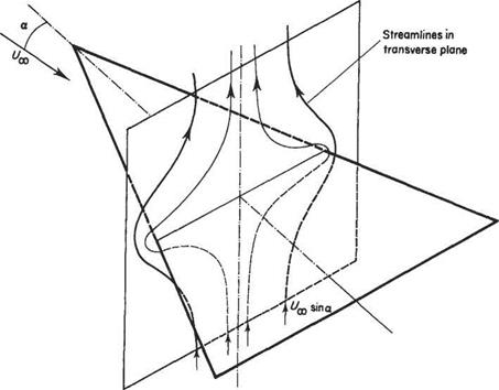
For the wings of large aspect ratio considered in Sections 5.5 and 5.6 above it was assumed that the flow around each wing section is approximately two-dimensional. Much the same assumption is made at the opposite extreme of small aspect ratio. The crucial difference is that now the wing sections are taken as being in the spanwise direction, see Fig. 5.39. Let the velocity components in the (x, y, z) directions be separated into free stream and perturbation components, i. e.

(Uoo cos a + u Ux sin a + v’, w’) (5.70)

Wings of small aspect ratio

Fig. 5.39 Approximate flow in the transverse plane of a slender delta wing from two-dimensional potential flow theory

Let the velocity potential associated with the perturbation velocities be denoted by ip’. For slender-wing theory ip’ corresponds to the two-dimensional potential flow around the spanwise wing-section, so that

Подпись:dV dV_

dy2 dz2

Thus for an infinitely thin uncambered wing this is the flow around a two-dimen­sional flat plate which is perpendicular to the oncoming flow component, sin a. The solution to this problem can be readily obtained by means of the potential flow theory described above in Chapter 3. On the surface of the plate the velocity potential is given by

Подпись: (5.72)p’ = ±Uao sinasj(b/2)2 — z2

where the plus and minus signs correspond to the upper and lower surfaces respect­ively.

As previously with thin wing theory, see Eqn (4.103) for example, the coefficient of pressure depends only on vl = dpt/dx. x does not appear in Eqn (5.71), but it does appear in parametric form in Eqn (5.72) through the variation of the wing-section width b.

Wings of small aspect ratio

For the delta wing b = 2x tan A so that

Wings of small aspect ratio Подпись: (5.76)

Eqn (5.75) then gives

The drag is found in a similar fashion except that now the pressure force has to be resolved in the direction of the free stream, so that Cd ос sin a whereas Q, oc cos a therefore

Подпись: (5.77)CD = Cl tan a

For small a, sin a ~ tana ~ a. Note also that the aspect ratio (AR) = 4 tanA and that for small a Eqn (5.76) can be rearranged to give

2тг tan A

Thus for small a Eqn (5.77) can also be written in the form

Подпись:Подпись: CD = аСд =2СІ

7Г (AR)2

Note that this is exactly twice the corresponding drag coefficient given in Eqn (5.43) for an elliptic wing of high aspect ratio.

At first sight the procedure outlined above seems to violate d’Alembert’s Law (see Section 4.1) that states that no net force is generated by a purely potential flow around a body. For aerofoils and wings it has been found necessary to introduce circulation in order to generate lift and induced drag. Circulation has not been introduced in the above procedure in any apparent way. However, it should be noted that although the flow around each spanwise wing section is assumed to be non­circulatory potential flow, the integrated effect of summing the contributions of each wing section will not, necessarily, approximate the non-circulatory potential flow around the wing as a whole. In fact, the purely non-circulatory potential flow around a chordwise wing section, at the centre-line for example, will look something like that shown in Fig. 4.1a above. By constructing the flow around the wing in the way described above it has been ensured that there is no flow reversal at the trailing edge and, in fact, a kind of Kutta condition has been implicitly imposed, implying that the flow as a whole does indeed possess circulation.

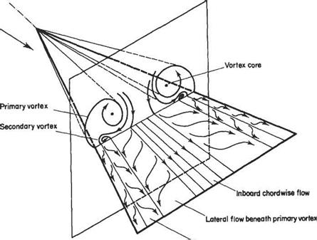
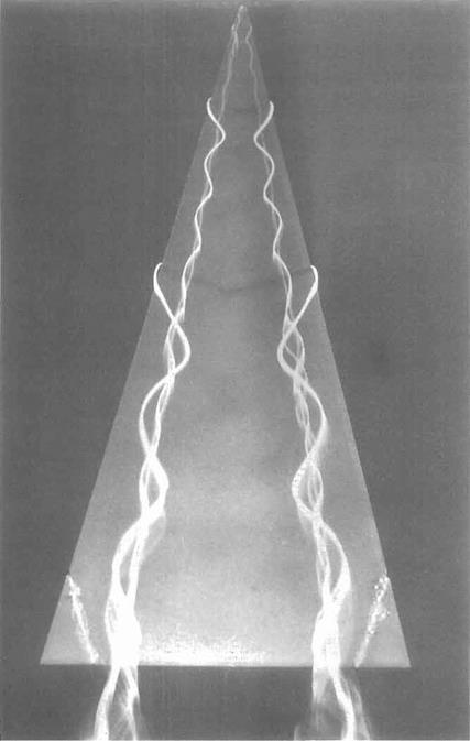
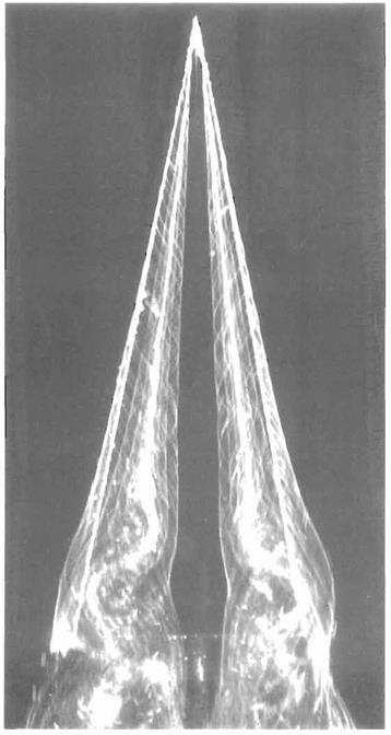
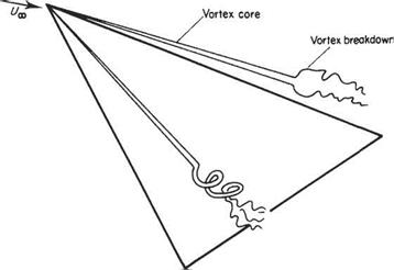
The so-called slender wing theory described above is of limited usefulness because for wings of small aspect ratio the ‘wing-tip’ vortices tend to roll up and dominate the flow field for all but very small angles of incidence. For example, see the flow field around a slender delta wing as depicted in Fig. 5.40. In this case, the flow separates from the leading edges and rolls up to form a pair of stable vortices over the upper surface. The vortices first appear at the apex of the wing and increase in strength on moving downstream, becoming fully developed by the time the trailing edge is reached. The low pressures generated by these vortices contribute much of the lift.

Wings of small aspect ratio

Tip flow beneath secondary vortex

Fig. 5.40 Real flow field around a slender delta wing, showing vortex structure and surface flow pattern


Pohlhamus[27] offered a simple way to estimate the contribution of the vortices to lift on slender deltas (see Figs 5.41 and 5.42). He suggested that at higher angles of incidence the potential-flow pattern of Fig. 5.39, be replaced by a separated flow pattern similar to that found for real flow around a flat plate oriented perpendicular to the oncoming flow. So, in effect, this transverse flow generates a ‘drag force’ (per unit chord) of magnitude

Wings of small aspect ratio

where Cdp has the value appropriate to real flow past a flate plate of infinite span placed perpendicular to the free stream (i. e. Cdp — 1.95). Now this force acts per­pendicularly to the wing and the lift is the component perpendicular to the actual free stream, so that

This component of the lift is called the vortex lift and the component given in Eqn (5.76) is called the potential flow lift.

Wings of small aspect ratio

Fig. 5.41 Vortices above a delta wing: The symmetrical pair of vortices over a delta wing are made visible by the use of dye in water flow. The wing is made of thin plate and has a semi-vertex angle of 15". The angle of attack is 20° and the Reynolds number is 20000 based on chord. The flow direction is from top to bottom. See also Fig. 5.40 on page 264. (The photograph was taken by H. Werle at ONERA, France.)

Wings of small aspect ratio

Fig. 5.42 Vortices above a delta wing: The symmetrical pair of vortices over a delta wing are made visible by the use of electrolysis in water flow. The wing is made of thin plate and has a semi-vertex angle of 10°. The angle of attack is 35° and the Reynolds number is 3000 based on chord. The flow direction is from top to bottom. Vortex breakdown occurs at about 0.7 maximum chord. See also Fig. 5.40 on page 264. (The photograph was taken by J.-L. Solignac at ONERA, France.)


« – v ‘ ‘ mu* ^ V

Potential flow lift Vortex lift

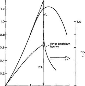
Подпись: CL = Kp sin a cos a -t- Ky sin2 a cos a ' ' > ' Подпись: (5.80)

The total lift acting on a slender delta wing is assumed to be the sum of the vortex and potential flow lifts. Thus

where Kp and K are coefficients which are given approximately by 2yrtanA and 1.95 respectively, or alternatively can be determined from experimental data. The potential-flow term dominates at small angles of incidence and the vortex lift at higher incidence. The mechanism for generating the vortex Uft is probably nonhnear to a significant extent, so there is really no theoretical justification for simply sum­ming the two effects. Nevertheless, Eqn (5.80) fits the experimental data reasonably well as shown in Fig. 5.43 where the separate contributions of potential-flow lift and vortex lift are plotted.

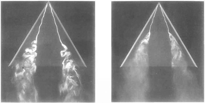
It can be seen from Fig. 5.43 that there is not a conventional stalling phenomenon for a slender delta in the form of a sudden catastrophic loss of Uft when a certain angle of incidence is reached. Rather there is a gradual loss of lift at around a — 35°. This phenomenon is not associated directly with boundary-layer separation, but is caused by the vortices bursting at locations that move progressively further upstream as the angle of incidence is increased. The phenomenon of vortex breakdown is illustrated in Fig. 5.45 (see also Figs 5.42 and 5.44).

1.4


o


О


10е 20е


30° 40е 50е


О


а


Fig. 5.43 Typical variation of lift coefficient with angle of incidence for a slender delta wing. PFL and VL denote respectively the contributions from the first and second terms on the right-hand side of Eqn (5.80)


Wings of small aspect ratio

Подпись: 268

(b) Re – 10 000


(a) Re = 5000


Fig. 5.44 Vortex breakdown above a delta wing: The wing is made of thin plate and its planform is an equilateral triangle. The vortices are made visible by the use of dye filaments in water flow. The angle of attack is 20°. In (a) where the Reynolds number based on chord is 5000 the laminar vortices that form after separation from the leading edge abruptly thicken and initially describe a larger-scale spiral motion which is followed by turbulent flow. For (b) the Reynolds number based on chord is 10000. At this higher Reynolds number the vortex breakdown moves upstream and appears to change form. The flow direction is from top to bottom. See also Fig. 5.42 on page 266. {The photographs were taken by H. Werle at ONERA, France.)


Wings of small aspect ratio

Wings of small aspect ratio

Fig. 5.45 A schematic view of the vortex breakdown over a slender delta wing, showing both the axisymmetric and spiral forms


Wings of small aspect ratio

Swept wings of finite span

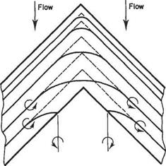
The yawed wing of infinite span gives an indication of the flow over part of a swept wing, provided it has a reasonably high aspect ratio. But, as with unswept wings, three-dimensional effects dominate near the wing-tips. In addition, unlike straight wings, for swept wings three-dimensional effects predominate in the mid-span region. This has highly significant consequences for the aerodynamic characteristics of swept wings and can be demonstrated in the following way. Suppose that the simple lifting­line model shown in Fig. 5.26, were adapted for a swept wing by merely making a kink in the bound vortex at the mid-span position. This approach is illustrated by the broken lines in Fig. 5.37. There is, however, a crucial difference between straight and kinked bound-vortex lines. For the former there is no self-induced velocity or downwash, whereas for the latter there is, as is readily apparent from Eqn (5.7). Moreover, this self-induced downwash approaches infinity near the kink at mid­span. Large induced velocities imply a significant loss in lift.

Swept wings of finite span

Fig. 5.37 Vortex sheet model for a swept wing

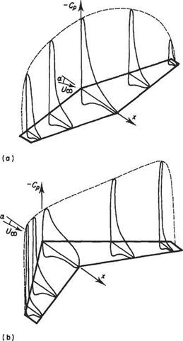
Nature does not tolerate infinite velocities and a more realistic vortex-sheet model is also shown in Fig. 5.37 (full lines). It is evident from this figure that the assump­tions leading to Eqn (5.32) cannot be made in the mid-span region even for high aspect ratios. Thus for swept wings simplified vortex-sheet models are inadmissible and the complete expression Eqn (5.31) must be used to evaluate the induced velocity. The bound-vortex lines must change direction and curve round smoothly in the mid-span region. Some may even turn back into trailing vortices before reaching mid-span. All this is likely to occur within about one chord from the mid­span. Further away conditions approximate those for an infinite-span yawed wing. In effect, the flow in the mid-span region is more like that for a wing of low aspect ratio. Accordingly, the generation of lift will be considerably impaired in that region. This effect is evident in the comparison of pressure coefficient distributions over straight and swept wings shown in Fig. 5.38. The reduction in peak pressure over the mid-span region is shown to be very pronounced.

Swept wings of finite span

Fig. 5.38 A comparison between the pressure distributions over straight and swept-back wings

The pressure variation depicted in Fig. 5.38b has important consequences. First, if it is borne in mind that suction pressure is plotted in Fig. 5.38, it can be seen that there is a pronounced positive pressure gradient outward along the wing. This tends to promote flow in the direction of the wing-tips which is highly undesirable. Secondly, since the pressure distributions near the wing-tips are much peakier than those further inboard, flow separation leading to wing stall tends to occur first near the wing-tips. For straight wings, on the other hand, the opposite situation prevails and stall usually first occurs near the wing root – a much safer state of affairs. The difficulties briefly described above make the design of swept wings a considerably more challenging affair compared to that of straight wings.

Swept and delta wings

Owing to the dictates of modern flight many modern aircraft have sweptback or slender delta wings. Such wings are used for the benefits they confer in high­speed flight – see Section 6.8.2. Nevertheless, aircraft have to land and take off. Accordingly, a text on aerodynamics should contain at least a brief discussion of the low-speed aerodynamics of such wings.

5.7.1 Yawed wings of infinite span

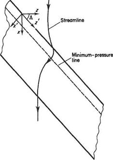
For a sweptback wing of fairly high aspect ratio it is reasonable to expect that away from the wing-tips the flow would be similar to that over a yawed (or sheared) wing of infinite span (Fig. 5.36). In order to understand the fundamentals of such flows it is helpful to use the coordinate system (У, y, z’), see Fig. 5.36. In this coordinate system the free stream has two components, namely Ux cos Л and sin Л, per­pendicular and parallel respectively to the leading edge of the wing. As the flow

Swept and delta wings

Swept and delta wings

Fig. 5.36 Streamline over a sheared wing of infinite span


approaches the wing it will depart from the freestream conditions. The total velocity field can be thought of as the superposition of the free stream and a perturbation field (г/, V, 0) corresponding to the departure from freestream conditions. Note that the velocity perturbation, W = 0 because the shape of the wing remains constant in the z! direction.

An immediate consequence of using the above method to construct the velocity field is that it can be readily shown that, unlike for infinite-span straight wings, the streamlines do not follow the freestream direction in the x—z plane. This is an important characteristic of swept wings. The streamline direction is determined by

Swept and delta wings(5.65)

When li = 0, downstream of the trailing edge and far upstream of the leading edge, the streamlines follow the freestream direction. As the flow approaches the leading – edge the streamlines are increasingly deflected in the outboard direction reaching a maximum deflection at the fore stagnation point (strictly a stagnation line) where 1/ = Uoo- Thereafter the flow accelerates rapidly over the leading edge so that 1/ quickly becomes positive, and the streamlines are then deflected in the opposite direction – the maximum being reached on the line of minimum pressure.

Another advantage of the (У, y, zf) coordinate system is that it allows the theory and data for two-dimensional aerofoils to be applied to the infinite-span yawed wing. So, for example, the lift developed by the yawed wing is given by adapting Eqn (4.43) to read

£ = ^/0(tf«cosA)2S^j^ (a„ — ao„) (5.66)

where a„ is the angle of incidence defined with respect to the x! direction and ao„ is the corresponding angle of incidence for zero lift. Thus

a„ = a/cosA (5-67)

so the lift-curve slope for the infinite yawed wing is given by

dQ,_/dC^ CQS^ ^ 27tcosA (5.68)

da V d« Jw

and

LoccosA (5.69)

Load distribution for minimum drag

Load distribution for minimum drag

Minimum induced drag for a given lift will occur if CD is a minimum and this will be so only if 8 is zero, since 8 is always a positive quantity. Since 8 involves squares of all the coefficients other than the first, it follows that the minimum drag condition coincides with the distribution that provides A3 = A5 — A7 = An = 0. Such a distri­bution is Г = 4sVAi sin# and substituting z = —s cos в

which is an elliptic spanwise distribution. These findings are in accordance with those of Section 5.5.3. This elliptic distribution can be pursued in an analysis involving the general Eqn (5.60) to give a far-reaching expression. Putting An — 0, n ф 1 in Eqn

(5.60)

Load distribution for minimum drag

gives

and rearranging

Load distribution for minimum drag(5.61)

Now consider an untwisted wing producing an elliptic load distribution, and hence minimum induced drag. By Section 5.5.3 the downwash is constant along the span and hence the equivalent incidence (a — ao — w/V) anywhere along the span is constant. This means that the lift coefficient is constant. Therefore in the equation

Подпись:1 ,

lift per unit span / = pVT = c

Load distribution for minimum drag

as / and Г vary elliptically so must c, since on the right-hand side C^pV2 is a constant along the span. Thus

and the general inference emerges that for a spanwise elliptic distribution an untwisted wing will have an elliptic chord distribution, though the planform may not be a true ellipse, e. g. the one-third chord line may be straight, whereas for a true ellipse, the mid-chord line would be straight (see Fig. 5.35).

It should be noted that an elliptic spanwise variation can be produced by varying the other parameters in Eqn (5.62), e. g. Eqn (5.62) can be rearranged as

V

T = CL-c

and putting

Cl = Яоо[(<* — <*o) – є] from Eqn (5.57) Г ос cax(a – ao) – є]

Thus to make Г vary elliptically, geometric twist (varying (a – ao)) or change in aerofoil section (varying ax and/or ao) may be employed in addition to, or instead of, changing the planform.

Returning to an untwisted elliptic planform, the important expression can be obtained by including c = cq sin в in p to give

Подпись: ^O^oo 8 s Подпись:p = po sin в where po =

Then Eqn (5.61) gives

Al

l + Mo

But

Ai = – fi-v from Eqn (5.47) TT{AK)

Now

Load distribution for minimum drag

Load distribution for minimum drag

Load distribution for minimum drag

Fig. 5.35 Three different wing planforms with the same elliptic chord distribution


Load distribution for minimum drag Подпись: r(AR)

and

for an elliptic chord distribution, so that on substituting in Eqn (5.63) and rearran­ging

Подпись:Подпись: a =1 + [а^/ж{АК)

This equation gives the lift-curve slope a for a given aspect ratio (A R) in terms of the two-dimensional slope of the aerofoil section used in the aerofoil. It has been derived with regard to the particular case of an elliptic planform producing minimum drag conditions and is strictly true only for this case. However, most practical aerofoils diverge so little from the elliptic in this respect that Eqn (5.64) and its inverse

1 – [a/ir{AR)

can be used with confidence in performance predictions, forecasting of wind-tunnel results and like problems.

Probably the most famous elliptically shaped wing belongs to the Supermarine Spitfire – the British World War II fighter. It would be pleasing to report that the wing shape was chosen with due regard being paid to aerodynamic theory. Unfortu­nately it is extremely doubtful whether the Spitfire’s chief designer, R. D. Mitchell, was even aware of Prandtl’s theory. In fact, the elliptic wing was a logical way to meet the structural demands arising from the requirement that four big machine guns be housed in the wings. The elliptic shape allowed the wings to be as thin as possible. Thus the true aerodynamic benefits were rather more indirect than wing theory would suggest. Also the elliptic shape gave rise to considerable manufacturing problems, greatly reducing the rate at which the aircraft could be made. For this reason, the Spitfire’s elliptic wing was probably not a good engineering solution when all the relevant factors were taken into account.[26]

General solution of Prandtl’s integral equation

This will be best understood if a particular value of в, or position along the span, be taken in Eqn (5.60). Take for example the position z = —0.5j, which is midway between the mid-span sections and the tip. From

z = —s cos 0, в = cos-1 j = 60°

General solution of Prandtl&#39;s integral equation General solution of Prandtl&#39;s integral equation

Then if the value of the parameter ^ is fi and the incidence from no lift is (c*i — aoi) Eqn (5.60) becomes

This is obviously an equation with A, A2, A3, A4, etc. as the only unknowns.

Other equations in which A, A2, A3, A4, etc., are the unknowns can be found by considering other points z along the span, bearing in mind that the value of fj, and of (a — ao) may also change from point to point. If it is desired to use, say, four terms in the series, an equation of the above form must be obtained at each of four values of в, noting that normally the values в = 0 and 7Г, i. e. the wing-tips, lead to the trivial

equation 0 = 0 and are, therefore, useless for the present purpose. Generally four coefficients are sufficient in the symmetrical case to produce a spanwise distribution that is insignificantly altered by the addition of further terms. In the case of sym­metric flight the coefficients would be Ai, A3, As, At, since the even harmonics do not appear. Also the arithmetic need only be concerned with values of в between 0 and 7t/2 since the curve is symmetrical about the mid-span section.

If the spanwise distribution is irregular, more harmonics are necessary in the series to describe it adequately, and more coefficients must be found from the integral equation. This becomes quite a tedious and lengthy operation by ‘hand’, but being a simple mathematical procedure the simultaneous equations can be easily pro­grammed for a computer.

The aerofoil parameters are contained in the expression

chord x two-dimensional lift slope

11 =———– ^——- :—————–

8 x semi-span

and the absolute incidence (a — ao). fi clearly allows for any spanwise variation in the chord, i. e. change in plan shape, or in the two-dimensional slope of the aerofoil profile, i. e. change in aerofoil section, a is the local geometric incidence and will vary if there is any geometric twist present on the wing. oo, the zero-lift incidence, may vary if there is any aerodynamic twist present, i. e. if the aerofoil section is changing along the span.

Example 5.3 Consider a tapered aerofoil. For completeness in the example every parameter is allowed to vary in a linear fashion from mid-span to the wing-tips.

Mid-span data Wing-tip data

3.048

Chord m

1.524

5.5

Ґ8СЛ,. -5— per radian

Ч^/оо

5.8

5.5

absolute incidence a°

3.5

Total span of wing is 12.192m

Obtain the aerofoil characteristics of the wing, the spanwise distribution of circulation, comparing it with the equivalent elliptic distribution for the wing flying straight and level at 89.4ms-1 at low altitude.

From the data:

Wing area 5 = 3£58 +L5!4 x 12.192 = 27.85m2

Aspect ratio (AR) = = 5.333

* 4 ‘ area 27.85

Подпись: chord c = 3.048 1 J.vto — l . 3.048 (m.~« ' 5.5 — 5.8 /z [1+ 5.5 fc)J a° = 5.5 1 -^0] Подпись:Подпись:©

Table 5.1

0

sin 0

sin 30

sin 50

sin 70

cos 0

тг/8

0.38268

0.923 88

0.923 88

0.38268

0.923 88

7t/4

0.70711

0.70711

-0.70711

-0.70711

0.70711

3tt/8

0.923 88

-0.38268

-0.38268

0.923 88

0.38268

7t,/2

1.00000

-1.00000

1.00000

-1.00000

0.00000

This gives at any section:

Cd

ц = —- = 0.34375(1 +0.5 cos 0)(1 -0.05455cos 0)

o S

and

fia = 0.032995(1 + O.5cos0)(l – 0.054 55 cos0)(1 + 0.363 64cos0)

where a is now in radians. For convenience Eqn (5.60) is rearranged to:

fia sin б = Asin0(sin0 + ц) + A3 sin30(sin0 + 3/i) + A5sin50(sin0 + 5/л)

+ A7 sin 70(sin 0 + 1ц)

and since the distribution is symmetrical the odd coefficients only will appear. Four coefficients will be evaluated and because of symmetry it is only necessary to take values of 0 between 0 and 7г/2, i. e. тг/8, 7t/4, 37t/8, 7t/2.

Table 5.1 gives values of sin0, sin лб, and cos 0 for the above angles and these substituted in the rearranged Eqn (5.60) lead to the following four simultaneous equations in the unknown coefficients.

0.0047 39 = 0.22079 A1 +0.89202 A3 + 1.25100 A5 +0.666 88 A7

0.011637 =0.663 19 Ai +0.98957 A3 – 1.315 95 A5 – 1.642 34 A7

0.021665 = 1.11573 A,. -0.679 35 A3 -0.896 54 Л5 + 2.68878 A7

0.032998 = 1.343 75 A -2.03125 A3 – 2.718 75 A5 – 3.40625 A7

These equations when solved give

А і = 0.020 329,Л3 = -0.000955, As = 0.001 029, A7 = -0.0002766

Thus

Г = 4sF{0.020 329 sin в – 0.000 955 sin 30 + 0.001029 sin 50 – 0.000 2766 sin 70} and substituting the values of 0 taken above, the circulation takes the values of:

0

0

тг/8

7t/4

Зтг/8

7t/2

zls і

1

0.924

0.707

0.383

0

Tm2s

0

16.85

28.7

40.2

49.2

Г/Го

0

0.343

0.383

0.82

1.0

General solution of Prandtl&#39;s integral equation

As a comparison, the equivalent elliptic distribution with the same coefficient of lift gives a series of values

TmV1 0 14.9 27.6 36.0 38.8

The aerodynamic characteristics follow from the equations given in Section 5.5.4. Thus:


General solution of Prandtl&#39;s integral equation

since


*=3(з:)2+5Ш2+7©1=0’02073


i. e. the induced drag is 2% greater than the minimum. For completeness the total lift and drag may be given


General solution of Prandtl&#39;s integral equation

Drag (induced) = CDy-pV2S = 0.007068 x 139910 = 988.82N

Example 5.4 A wing is untwisted and of elliptic planform with a symmetrical aerofoil section, and is rigged symmetrically in a wind-tunnel at incidence ai to a wind stream having an axial velocity V. In addition, the wind has a small uniform angular velocity ш, about the tunnel axis. Show that the distribution of circulation along the wing is given by

Г = 4sV[Ai sin 9 + A2 sin 29]

and determine A and Аг in terms of the wing parameters. Neglect wind-tunnel constraints.

(CU)

From Eqn (5.60)


p{a – ao) = EA„ sinпв( 1 +

sin 9/


In this case ao = 0 and the effective incidence at any section z from the centre-line

W Ш

a = ai +z— = ai ——scos9

Also since the planform is elliptic and untwisted p, = p$ sin# (Section 5.5.3) and the equation becomes for this problem


General solution of Prandtl&#39;s integral equation

Equating like terms:


jUo«i sin# = A( + po)sb#

= Aj[ +2/Uo)sin20 0 = Ai(l + 3/Uo) sin3# etc.

Thus the spanwise distribution for this case is

Г = 4sV[Ai sin в + Ai sin 29]

(—Л*___ ^

2(1 +2 к))

Подпись: and General solution of Prandtl&#39;s integral equation

and the coefficients are