Category AERODYNAMICS

THE COMPLEX POTENTIAL

Подпись: (6.12)

Подпись: ЭФ Эх Подпись: dz Подпись: ЭФ dz Подпись: эч> Эх

Consider a steady incompressible, inviscid, irrotational two-dimensional flow. The velocity potential and the stream function are related by the following equations (Eq. (2.81)):

and both satisfy Laplace’s equation. Note that Eq. (6.12) yields the Cauchy Riemann conditions for Ф and Ф to be the real and imaginary parts of an analytic function F of a complex variable. We define the complex potential as

Подпись: (6.13)F = Ф + і V

THE COMPLEX POTENTIAL Подпись: (6.14)

and note that its derivative

is the complex conjugate of the velocity and is called the complex velocity. Any analytic function of a complex variable can represent the complex potential of some flow.

VARIABLES

Approximate solutions to the exact potential flow problem are obtained in this book using both classical small-disturbance methods and numerical modeling. It is important to have exact solutions available to test the accuracy of the approximations and to assess their applicability. In this chapter complex variables will be used to obtain the solution to three model problems: the flat plate, the circular arc, and a symmetrical airfoil.

6.1 SUMMARY OF COMPLEX VARIABLE THEORY

Prior to applying complex variable methods to potential flow problems, some of the principles are discussed briefly (for more details about the mathematics of complex variables, see Churchill6л). To begin, first define the imaginary unit

і by

;2=-i (6.1)

Then any complex number У can be written as

Y = a + ib (6.2)

where a and b are real and are called the real and imaginary parts of Y,

Подпись: FIGURE 6.1 Complex plane.
image203

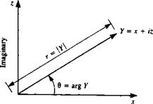
respectively. Every complex number therefore can be thought of as repre­senting an ordered pair of real numbers {a, b) and as such may be represented geometrically by points in a plane. The complex number У = x + iz is shown in Fig. 6.1 in a cartesian coordinate system with x and z axes. A polar coordinate version of Y with coordinates r and Q is also shown in the figure. Note that the absolute value of Y (|У|) is defined as л/х2 + z2 and the argument of У (arg У = в) is defined as tan-1 z/x. An exponential form of У is expressed as

Y = reie (6.3)

if the exponential term is defined as

cos 0 + i sin 6 = e, e (6.4)

The complex conjugate of the complex number У is defined as

Y = x — iz

Otherwise the algebra of complex numbers is similar to the algebra of the term (a + b), but note that i2 = — 1. As an example, the multiplication of a complex number by its conjugate is

YY = (x + iz){x-iz)=x2 + z2

A function / of the complex variable У can be written in terms of its real and imaginary parts as

f(Y) = g(x, z) + ih(x, z) (6.5)

Analytic functions of a complex variable are differentiable, which means that

= Hm /(У+АУ)-/(У) dY ду – о ДУ

exists for all possible paths АУ. Now consider the derivative of f(Y) along the x axis

df(Y) |jm Ag + iAh_3g ^dh dY д*—о Ax Эх Эх

Similarly, the derivative in the z direction is

df(Y) bg + ibh 1 dg dh dh. dg

—— = lim ————— — ~ ——I – —~ ~— і ~r~

dY /Аг—о 1 Az 1 dz dz dz dz

The derivatives must be independent of the direction of differentiation; therefore, equating the real and imaginary parts of these derivatives results in

3g_3h 3e = _Sh (66)

dx dz dz dx

So, differentiability is guaranteed if the real and imaginary parts of/satisfy the above equations, which are called the Cauchy-Riemann conditions. Also, if a function of a complex variable is analytic, then the real and imaginary parts each satisfy Laplace’s equation. Points in a region where /(У) is analytic are called regular points and points where f(Y) is not analytic are called singular points.

Consider the integration of a complex function. If the function is analytic and the region is simply connected, then the integral

image204

from point A to point В is independent of the path of integration and the integral around all closed paths is zero. The latter result is called the Cauchy Integral Theorem. Multiply connected regions are of interest since they include the region exterior to a two-dimensional airfoil as well as the region remaining once singular points are excluded by surrounding them with closed curves. Consider the region in Fig. 6.2 that is exterior to n curves Clt C2, ■ ■ ■, Cn and consider a curve C that surrounds the n curves. An application of the Cauchy Integral Theorem in this region for a function / that is analytic inside C and outside the n curves yields the result that the integral around C is equal to the sum of the integrals around the n curves where all of the internal integrations are in the same direction:

j>f(Y)dY = f f(Y)dY + j> f(Y)dY+-■- + j> f(Y)dY (6.7)

Consider the following results for power series expansions of the function f(Y). If / is analytic at all points within a circle C0 with center at Y0, then at each point У inside the circle / can be represented by the Taylor series expansion

f(Y) =/(У0) +/'(У0)(У – Уо) + ■ • (У – УоГ + • • • (6.8)

n

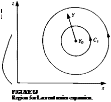
Now consider the region exterior to the circle Ci whose center is at У0 in Fig. 6.3. The function / is analytic in the annular region between C, and C2.

Then / can be represented by the Laurent series expansion

f(Y) = ?,An(Y-Y0y (6.9)

—oo

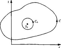
Consider now the integration of a function with singularities. Let /(Y) be analytic inside the curve C except at Y0. Surround Y0 by the circle C„ (see Fig. 6.4) and represent/between C0 and C by the Laurent series of Eq. (6.9). Then the integral around C becomes

<j> /(Y) dY = І aA (Y – Yo)" dY = 2ліА-і (6.10)

Jc – oo JcB

where A-t is the coefficient of the term Л_,/(У — Y0) and is called the residue of f(Y) at Y0. If /(Y) is analytic inside C except at a finite number of singularities (N), then a generalization of Eq. (6.10) leads to the Residue Theorem:

Подпись: (6.11)lf(Y)dY = 2m%A-l(Yj) Jc /=1

image205

image206

FIGURE 6.4

Integration of a function with singularities.

image208

FIGURE 6.5

Mapping with a function of a complex variable.

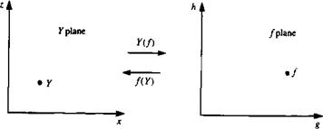
Complex variable theory is a powerful tool for the solution of two – dimensional incompressible potential flow problems through its mapping properties. Consider the function f(Y), that generates the pair of values (g, h) for each pair of values (x, z). Each value of У represents a point in the Y plane and each value of / can be thought of as representing a corresponding point in the / plane. The function f(Y) therefore geometrically maps or transforms points (and also curves and regions) from the У plane to the / plane (see Fig.

6.5) .

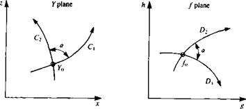
When the mapping function /(У) is analytic, the mapping from the У plane to the f plane is called conformal and has the following special property. Consider a curve C through the point Y0 in the У plane and the corresponding curve D through the corresponding point f0 in the / plane (Fig. 6.6). If / is analytic at!<, and if f'(Y0) Ф 0 then every curve through lo in the У plane is rotated by the amount arg/'(y0) when it is transformed into the /plane. This is illustrated in Fig. 6.6, which shows the two curves Cx and C2 that intersect at У0 in the У plane and the corresponding curves D, and D2 that intersect at f0 in the f plane. For this conformal mapping, it is observed that the angle of intersection between the curves is preserved in the transformation. A point at

image209

FIGURE 6.6

Preservation of the angle between intersecting curves for a conformal transformation.

which f'(Y) = 0 is called a critical point of the mapping and at a critical point the above intersection angle is not preserved.

SUMMARY AND CONCLUSIONS FROM THIN AIRFOIL THEORY

Up to this point, in order to be able to solve practical problems, the fluid dynamic equations were considerably simplified and even the boundary conditions were approximated. However, in spite of these simplifications, some very important results were obtained in this chapter:

1. The lift slope of a two-dimensional airfoil is 2л as shown by Eq. (5.66).

2. The pitching moment at the aerodynamic center (at cl4) is independent of angle of attack (excluding airfoil’s stalled conditions).

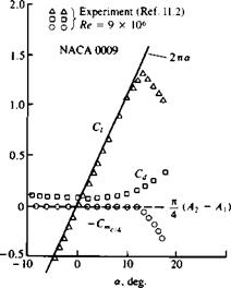
These two very important results are very close to experimental data in the low angle of attack range, as shown in Fig. 5.19. When the angle of attack

FIGURE 5.19

image197Lift and pitching moment of a NACA 0009 airfoil.

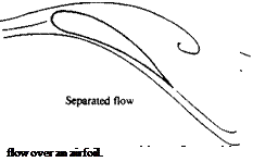
increases beyond the limits of the small angle of attack assumption, the streamlines do not follow the airfoil surface shape (Fig. 5.20) and the flow is considered to be separated. This results in loss of lift, as indicated by the experimental data in Fig. 5.19 (for a> 10°) and this condition is called airfoil stall.

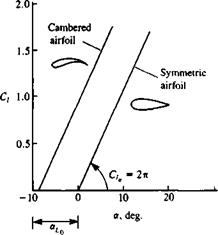
3. Airfoil camber does not change the lift slope and can be viewed as an additional angle of attack effect (au in Eq. (5.66)). This is shown schematically by Fig. 5.21. The symmetric airfoil will have zero lift at ar = 0 while the airfoil with camber has an “effective” angle of attack that is larger

by <*u-

4.

image199

The trailing edge section has a larger effect on the above camber effect. Therefore, if the airfoil lift needs to be changed without changing its angle

FIGURE 5.21.

image200Schematic description of airfoil camber effect on the lift coefficient.

of attack, then changing the chordline geometry (e. g., by flaps, or slats) at the trailing edge region is more effective than at the leading edge region.

5. The effect of thickness on the airfoil lift is not treated in a satisfactory manner by the small-disturbance approach, but will be calculated more accurately in the following two chapters.

6. The two-dimensional drag coefficient obtained by this model is zero and there is no drag associated with the generation of two-dimensional lift. Experimental airfoil data, however, includes drag due to the viscous boundary layer on the airfoil, which should be included in engineering calculations. The experimental drag coefficient values for the NACA 0009 airfoil are also plotted in Fig. 5.19 and for example the “zero-lift” drag coefficient is close to Cd = 0.0055.

THE LUMPED-VORTEX ELEMENT

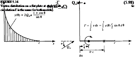
Based on the results obtained for the lifting symmetrical airfoil (flat plate), it is possible to develop a simple “lifting element.” The vortex distribution on such a flat plate airfoil can be obtained from Eq. (5.48) as

y(e)-=2Q00a]-r^0^- (5.97)

sin a

which is shown schematically in Fig. 5.16a. From a far field point of view, this can be replaced by a single vortex with the same strength Г = y(x) dx.

Since the lift of the symmetric airfoil

L = PQS

acts at the center of pressure (at the quarter-chord for the flat plate), the concentrated vortex is placed there.

If the lifting flat plate is to be represented by only one vortex Г, then the boundary condition requiring zero normal flow at the surface can be specified

image193,image194

at only one point too. Assuming that this point is at a distance к • c along the x axis (Fig. 5.166) then the boundary condition of zero normal velocity can be specified as

In order for this model to simulate the results of the thin airfoil the corresponding value of the circulation for a flat plate (Eq. (5.72)) is substituted:

Г = ncQ^a

Подпись: thus

Подпись:-jrcQ^a 2л(кс — |c)

The solution of this equation provides the point at which the boundary condition needs to be specified, which is called the collocation point:

к = (5.99)

Note that this representation is based on results that account for the Kutta condition at the trailing edge. This is the main reason for some of the good approximations that can be obtained when using this model. Some of the advantages of using this lifting element for the estimation of some aerodynamic effects are shown in the following examples.

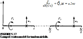
Example 1: Tandem airfoils. The useful application of this simple model can be demonstrated by investigating the lift of the two-airfoil system, shown in Fig. 5.17. The circulations of the two airfoils are represented by Г, and Г2, and the

THE LUMPED-VORTEX ELEMENT Подпись: (5.100a)

two boundary conditions at the two collocation points, which require that the normal velocity component will be zero, are w, = tv2 = 0. The normal velocity component at each collocation point consists of the influence of the two vortices and the free stream normal component and when specified at these points the two boundary conditions are:

Подпись: (5.1006)Подпись:—г —r2

—— 1—– =—t-

2л2с 2л(с/2)

The solution of this system is

Подпись:Г, = I iicQ^a Г2 = І лсО„а

Thus, clearly, the front airfoil has a larger lift due to the upwash induced by the second airfoil, and because of the same but reversed interaction the second airfoil will have less lift. Also, this effect is stronger when the airfoils are closer and the interaction will disappear as the distance increases. The importance of this result is that the immediate effects of the tandem airfoil configuration could be estimated with minimum effort.

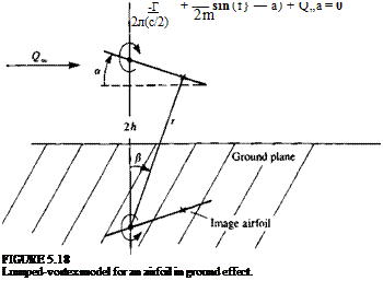
Example 2: Ground effect. Another simple example is the airfoil near the ground, which is modeled by using the mirror-image method (Fig. 5.18). In order to create a straight streamline at the ground plane, two symmetrically positioned airfoils are considered. Again, using the lumped vortex element, the normal velocity component at the collocation point due to the bound vortex is —Г/2л(с/2). The influence of the image vortex, which has the same strength but in the opposite direction and is located at a distance 2h under the primary vortex, is then

Here r = V4h2 + c2/4 is the distance from the image vortex to the collocation point, and sin f} = (c/2)/r. Requiring that the sum of the contributions to the

THE LUMPED-VORTEX ELEMENT Подпись: (5.102)

normal velocity component at the collocation point is zero yields

Assuming a is small compared to |8 (equivalent to assuming that the circulation is linear in a) results in

4h2 + c2I4 г с2 l

T(h) = T(h=cc) – ^ =Г(Ь=сф+— j (5.103)

Here Г(Л) is the value of circulation with ground proximity and this result clearly indicates that the circulation (and lift) will be increased by the proximity of the ground.

AERODYNAMIC FORCES AND MOMENT ON A THIN AIRFOIL

For a given airfoil geometry, the mean camberline tjc(x) is a known function and the coefficients A0, Au A2,. . . can be computed by Eq. (5.51) and Eq.

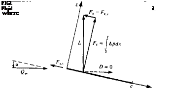
(5.52) . The pressure difference across the thin lifting surface Ap(x) can be calculated by Eq. (5.43) and the aerodynamic coefficients can be evaluated. These aerodynamic coefficieits are usaally defined in the frec-stre im coordin­ate system such that the lift is normal and the dlag force is parallel to the free-stream flow. In order to determine the aerodynamic lift and drag, consider the simple case shown in Fig. 5.11. The pressure difference can be evaluated by using Eq. (5.43):

Др(дг) = pG«y(x)

and since a is small is used instead of Qa cos a. The normal force Fz is then

image180(5.54)

Also, the flat plate of Fig. 5.11 is very thin and the x component of the force is zero:

Fx = 0

Based on this formulation, the lift and drag forces become

L = FZ D = Fza

On the other hand, the Kutta-Joukowski theorem in Section 3.11 clearly states that the lift is perpendicular to the free-stream Q„. Thus, the aerodynamic lift is

Подпись: (5.55)L = pQS

and the aerodynamic drag is

Подпись: D = 0(5.56)

Therefore, an additional force must exist in order to balance these two calculations. This force is called the leading edge suction force Fx s, and is a result of the very high suction forces acting at the leading edge (where q -* » and the local leading edge radius is approaching zero). The strength of this leading edge suction force is calculated in Section 6.5.2 using the exact solution near the leading edge of the flat plate (which is similar to the treatment of this problem by Lighthill5 4) and for the small angle of attack case is:

Подпись: (5.57)

image181

Fxs=-pQSa

This force cancels the drag component of the thin lifting airfoil obtained by integrating the pressure difference, so that the two-dimensional drag becomes zero. This result that the aerodynamic drag in two-dimensional inviscid
incompressible flow is zero was obtained in 1744 by the French mathematician d’Alembert and hence known as d’Alembert’s Paradox. Exact solutions and numerical computations of the thick airfoil problem (where the velocity at the leading edge is finite) will verify this result in the following chapters.

To evaluate the lift of the thin airfoil, the circulation of Eq. (5.54) is calculated

T=f y(x)dx= y(0)^sin0d0 Jo Jo l

„ _ г Г 1 + cos 0 A 1c

= 2Qo= A0 —:—-—h 2 A„ sin (n0) – sin 0 dd

Jo L sin 0 n=1 J 2

Recalling that

[ (1 + cos 0) dd = я Jo

and that the integral of sin пв sin 0 is nonzero only if n = 1,

Г ■ a • a JO 1*4 when n –

I sinn0sin 0d0 = I )

Jo VO when пФ 1/

the circulation becomes

Подпись: (5.58)Подпись:Г = Є»ся(Ло + ^)

The lift per unit span is obtained from Eq. (5.55) and is

This equation indicates that only the first two terms of the circulation (shown in Fig. 5.10) will have an effect on the lift and the integration over the airfoil of the higher-order terms will cancel out. The pitching moment about the у axis is positive for a clockwise rotation; therefore, a minus sign needs to be included when calculating the moment Af0 relative to the airfoil’s leading edge

M0= — ( Apxdx = pQaof y(0)~(1 — cos 0)^sin 0dd Jo Jo 2 2

= —-Г + —J y(0) sin 0 cos 0 dd j

After some trigonometric manipulations this results in

Подпись:, . c w C2 ,/ ЛЛ

Mo 2L + + A2-J

and by substituting the results for the lift:

Подпись:Mo = – pQln j(a0 + At – yJ

The moment M along the x axis can be described in terms of the lift and the moment at the leading edge as

M = M0 + x • Fz = M0 + x • L

The center of pressure xcp is defined as the point where the moment is zero (this can be considered to be the point where the resultant lift force acts):

image182 AERODYNAMIC FORCES AND MOMENT ON A THIN AIRFOIL

M = M0 + xcp • L = 0

An observation of the coefficients of the circulation (Eqs. (5.51) and

(5.52) ) reveals that only the first term A0 is a function of angle of attack a. Substituting A0 into the lift coefficient equation yields

Подпись: C,image183(5.65)

Also, for a flat plate dr]c/dx = 0 and thus all terms, except 2ла, in Eq. (5.65) will vanish. Therefore, the terms including the effect of the camberline r)c are independent of angle of attack and are a constant for a particular chordline shape. This allows us to write the lift coefficient as

С, = 2к(ос – аи) (5.66)

where ais called the zero-lift angle and is a function of the camber. Substituting the value of At from Eq. (5.52) yields

Подпись: (5.67)

By using the Bt coefficients of Eq. (5.50a) the lift coefficient becomes

С, = 2л(а – B0 + y) (5.62a)

Comparing with Eq. (5.66) indicates that the zero-lift angle can readily be obtained as

*L„ = So-y (5.67 a)

The lift slope can be defined as

dC

C, ‘ = 2л (5.68)

* да v ‘

Equations (5.66-5.68) show that the lift slope of a two-dimensional airfoil is 2л, and that the camber will have an effect similar to an angle of attack increment Дог, but will not change the lift slope.

Next, the pitching moment coefficient (Eq. (5.64)) can be rewritten, using the formula for the lift coefficient (Eq. (5.62)), thus

Cmo=-^ + ^(A2-A1) (5.69)

Since the coefficients Alt A2 are independent of angle of attack, only the first term in this equation depends on a. Therefore, if the moments are calculated relative to the airfoil quarter-chord point the first term in this equation disappears and the moment at this point becomes independent of angle of attack. This point is called the aerodynamic center xac and according to thin airfoil theory it is located at the quarter chord. Consequently the pitching moment measured at this point is only due to the second term in Eq. (5.69):

СтсМ = ^(Л2-Л0 (5.70)

The use of this formulation for some simple chord-line shapes is demonstrated in the following examples.

Example 1: Flat plate. As a first example, consider the thin, lifting model of a symmetric airfoil that is represented by a flat plate (shown in Fig. 5.12a). For this particular case there is no camber and rjc(x) = 0. Consequently, all terms having derivatives of the camberline will vanish, and the circulation coefficients become

A0= a A1=A2=— = 0 (5.71)

The circulation Г for the flat plate airfoil is then

Г = Q^xca (5.72)

and the lift and moment are obtained by substituting Eq. (5.71) into Eqs. (5.59)

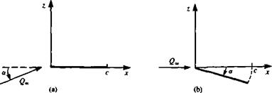
Подпись: FIGURE 5.12 Free-stream and body coordinate systems for a flat plate at an angle of attack, and (5.60): L = pQS = pQlnca (5.73] Mo= -pQin—a 4 (5-74] The lift and pitching moment coefficients are C, = 2 ла (5.75) Cm — — — oc (5.76)

and the lift slope is again 2л as was shown in Eq. (5.66). The center of pressure ii at

Подпись: (5.77)

image184

%cp 1

c Ci 4

Thus, for the symmetric thin airfoil, the center of pressure and the aerodynamic center are located at the quarter-chord location.

Подпись: rj(x) = - ax Подпись: a
image185

Because of the transfer of the boundary condition to the z = 0 plane, the airfoil trailing or leading edge can be at a certain small distance from this plane (as long as tj(x)« c). As an example, let’s solve this problem in the free-stream coordinate system, as shown in Fig. 5.126. In this case the free-stream angle of attack is zero, but the chord can be expressed as

Substituting this into Eqs. (5.51) and (5.52) yields

Aa = a and Aj = A2 = ■ • ■ — 0

which is the same result as in Eq. (5.71). Thus both methods will lead to the same results.

image186 Подпись: (5.78)

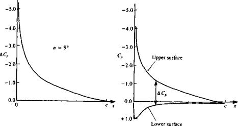
For the symmetrical airfoil, the pressure coefficient difference ДCp can be found from Eq. (5.44u) by substituting A0 and the corresponding circulation

AERODYNAMIC FORCES AND MOMENT ON A THIN AIRFOIL

image187

(a) (b)

FIGURE 5.13

Calculated chordwise pressure difference for a symmetric airfoil and calculated upper and lower surface pressures for a NACA 0009 airfoil.


In terms of x (with Eq. (5.45)) this becomes

Подпись: (5.79)

The result of this formulation is presented in Fig. 5.13a. In Fig. 5.13ft a comparison is made with the results of a more accurate method (e. g., panel method) for a NACA 0012 symmetric airfoil. This indicates that the pressure difference is closely predicted over most of the airfoil. Near the leading edge, however, the flat plate solution is singular and the model is not accurate there.

Example 2: Thin airfoil with a parabolic camber. As an example for a simple nonsymmetric chordline shape consider the parabolic camberline shown in Fig. 5.14, with є being its maximum height. The equation of the camberline is then

*lc(x) = 4f“ [l “ “j (5.80)

Z і к

Подпись: о Подпись: с Подпись: лг Подпись: FIGURE 5.14 Parabolic arc airfoil.

П(а)

(5.81)

Подпись: dr)c(x) € dx c image188"

image189 Подпись: = 4 - cos 0 c Подпись: (5-82)

Expressing this term by using the transformation x = (c/2)(l – cos в) results in

The coefficients Л„ can be found by substituting this into Eqs (5.51) and (5.52). Because of the orthogonal nature of the integral Jj cos пв cos тв d6 all terms where m Ф n will vanish. So in this case, when m = 1

An = a – 0

and only the first additional coefficient will be nonzero:

A,=4- A2 = А->= ■ ■ ■ A„ =0 c

This result can be found immediately by comparing Eq. (5.50a) with the, camberline slope

^ ^ ^ fl„ cos (пв) = 4-cos в

dx л=o £

Therefore, clearly Bx = 4e/c and the other B„ coefficients are zero.

The lift and the moment of the parabolic camber airfoil can be obtained by substituting these results into Eqs. (5.59) and (5.60):

L = pQljic(^a + 2

(5.83)

M0= ~pQln^[a + 4^j

(5.84)

and the corresponding aerodynamic coefficients are

C, = 2jr(a + 2^ (5.85)

C.* =-§(« + 4^) (5.86)

When comparing this result for the lift with Eq. (5.66) the zero-lift angle is found to be

<^=-2- (5.87)

c

This means that this airfoil will have zero lift when it is pitched to a negative angle of attack with a magnitude of 2e/c.

The center of pressure is obtained by dividing the moment by the lift

Подпись:e

(5.88)

Note that at a = 0 the center of pressure is at the midchord and as the angle of attack increases it moves toward the quarter chord.

Also, in this case the pitching moment about the aerodynamic center can be calculated using Eq. (5.70):

image191(5.89)

which indicates that the portion of the moment that is independent of the angle of attack increases with increased curvature (as e/c increases) of the camberline.

Example 3: Flapped airfoil. One of the most frequently used control devices is the trailing-edge flap. The reason for mounting such a device at the trailing edge can be observed by examining the (cos 0-1) term in Eq. (5.67). This implies that the zero-lift angle is most influenced by the trailing-edge region where 0—* therefore, relatively small deflections of the flap at the trailing edge will have noticeable effect.

AERODYNAMIC FORCES AND MOMENT ON A THIN AIRFOIL AERODYNAMIC FORCES AND MOMENT ON A THIN AIRFOIL

To demonstrate the effect of the trailing-edge flap consider the following simple example. Here the main airfoil plane is placed on the x axis, and at a chordwise position к – c the flap is deflected by bf, as shown in Fig. 5.15. The trailing edge of the deflected airfoil is now not on the x axis but owing to the small disturbance approximation of the boundary condition the error due to the use of this coordinate system is within the accuracy of thin airfoil theory. It is assumed that the airfoil is continuous, and there is no gap at the flap hinge point. The slope of the camberline, for the case shown in the figure, is

image192Подпись: -► X FIGURE 5.15

Thin flapped airfoil (without a gap at point к • c).

range 0k —* я, resulting in

Подпись: Since the coefficients A„ are given as a function of the variable 0, the location of' the hinge point вк can be found by using Eq. (5.45). kc=~(l— cos 6k), => cos вк = 2k — 1 The coefficients of Eqs. (5.51) and (5.52) are computed now only between the '

і ся 3

A0 = a + ~ dfd6 = a + -(n-6k) (5.91вИ

я ]вк я

An=–f Sf cosnOdO = —^-^ (5.91b)

Я )вк я n

By substituting the values of the first three A„ coefficients into Eqs. (5.62) and (5.64) the lift and pitching moment coefficients are obtained:

By setting a = 0 the incremental effect of the flap is obtained:

AC, = [2(я – вк) + 2 sin вк]6, (5.94)

ACmo = – j[(jr – вк) + 2 sin вк – sin 2ek6f (5.95)

The increment in the moment at the aerodynamic center, c/4, due to the flap deflection, is obtained using Eq. (5.70) as

AC„clk = Ц sin 2вк-{ sin ek]df (5.96)

CLASSICAL SOLUTION OF THE LIFTING PROBLEM

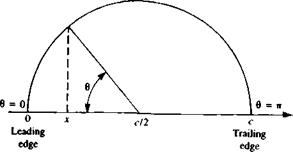
The solution for the velocity distribution, pressure difference, and the aerodynamic loads on the thin, lifting airfoil requires the knowledge of the vortex distribution y{x) on the airfoil. This can be obtained by solving the integral equation (Eq. ((5.39)), which is a form of the zero normal flow boundary condition. The classical approach (e. g., Glauert,52 p. 88) is to approximate y(x) by a trigonometric expansion and then the problem reduces to evaluating the values of this expansion’s coefficients. Therefore, a transfor­mation into trigonometric variables is needed. Such a transformation is described by Fig. 5.9 and is

jc =^(1 – cos в) (5.45)

and

Подпись: FIGURE 5.9 Plot of the transformation jr = c/2(l - cos в).
image172

dx = I sin в dd (5.45a)

Подпись: -1 2 я image173,image174 Подпись: (5.46)

Note that the airfoil leading edge is at x = 0 (0 = 0), and the trailing edge is at x = с (0 = я). Substituting Eq. (5.45) into Eq. (5.39) results in the transformed integral equation.

0< в< я

This integration with 0O should hold for each point x (or 0) on the airfoil. The transformed Kutta condition now has the form

у(л) – 0 (5.47)

The next step is to find a vortex distribution that will satisfy these last two equations. A trigonometric expansion of the form

X A„ sin (я0)

n = l

image175

will satisfy the Kutta condition, and is general enough that it can be used to represent the circulation distribution. However, experimental evidence shows a large suction peak at the airfoil’s leading edge, which can be modeled by a function whose value is large at the leading edge and reduces to 0 at the trailing edge. Such a trigonometric expression is the cotangent function, which will be included, too, in the proposed vortex distribution:

The suggested solution for the circulation is shown graphically in Fig. 5.10, and in order to cancel the 2term on the right-hand side of Eq. (5.46) the proposed function for the vortex distribution will be multiplied by this constant:

У(0) = 2(2®[а0—+ 2) A„sin(n0)l (5.48)

L sin 0 я=і J

Подпись: FIGURE 5.10 Schematic description of the first four terms in the series describing the circulation.

An additional advantage of the first term is that it induces a constant downwash on the airfoil, as will be evident later on (see Eq. (5.53)). In order to determine the values of the An constants, Eq. (5.48) is substituted into Eq.

(5.49)

In this equation, each point 0 is influenced by all the vortex elements of the airfoil—this requires the evaluation of the integral for each value of 0. Recalling Glauert’s integral

Подпись:fя COS П0О,7rsinn0

— s——- —2de0 = ——

and replacing 1 by cos 00, the first term of the integral becomes

1 . Г cos O0o + cos 0O sin 0O de0 1 . . .

—— r—z———- 2——- о=“~Ло(0 + л:) = – A0

Л J0 sin 0O cos 0O – COS 0 Л

whereas for the terms with the coefficients A,,A2,…, the following trigonometric relation is used:

sin /100 sin 0O = ^ [cos (n — 1)0O — cos (n + 1)0O] n = 1, 2, 3,…

This allows the presentation of the nth term in the following form:

1 г Г„ • / л i sin 00 de0

— I A„ sin (n0o) ——————-

Я Jo 1 П cos 0O – cos 0

__ А гЛ ACL

Подпись: COS 0O - cos 0= ——- [cos (n – 1)0O – cos (n + 1)0O] 0

2n Jo

and by using Glauert’s integral this reduces to

An fsin(n-l)0 sin (n + 1)01 2л L sin 0 sin 0 J

Подпись: sin 0 cos (n0) sin 0

image177 image178

j = An cos (n0)

Substituting this into Eq. (5.49) yields

-A0 + 2 An cos (n&) = ~~T~~ ~ a (5.50)

«=i dx

This is actually a Fourier expansion of the right-hand side of the equation, which includes the information on the airfoil geometry. Multiplying both sides of the equation by cos тв and performing an integration from 0-* я, for each value of n, will result in the cancelation of all the nonorthogonal multipliers (where тФп). Consequently for each value of n the value of the correspond-

image179 CLASSICAL SOLUTION OF THE LIFTING PROBLEM Подпись: n = 0 Подпись: (5.51)

ing coefficient A„ is obtained:

2 [ йПс(в)со&пвав n = 1, 2, 3, . . . (5.52)

л Jo dx v ‘

Note that Eq. (5.50) can be rewritten as an expansion of the downwash distribution w = w(d) on the airfoil as

jr = – Ao + E An cos (пв) (5.53)

n = l

and it is clear that the downwash due to the first term (multiplied by A0) of the vortex distribution is constant along the airfoil chord.

CLASSICAL SOLUTION OF THE LIFTING PROBLEM Подпись: (5.50a)

The slope drjc/dx can be expanded as a Fourier series such that

and a comparison with Eq. (5.50) indicates that B0=a-A0 Bn=An n =

This allows the simplification of Eq. (5.53) such that the angle of attack and camber contributions to the downwash are explicitly displayed. A replacement of the An coefficients with the B„ coefficients in Eq. (5.53) results in

= – a + 2) B„ cos (пв) (5.53a)

Q°° n=0

ZERO-THICKNESS AIRFOIL AT ANGLE OF ATTACK

It was demonstrated in Section 4.3 that the small-disturbance flow over thin airfoils can be divided into a thickness problem and a lifting problem due to angle of attack and chord camber. In this section the lifting problem will be addressed, using the classical approach (Glauert,52 pp. 87-93). To illustrate the problem, consider a thin cambered airfoil, at an angle of attack a, as shown schematically by Fig. 5.6. The flow is assumed to be inviscid, incompressible, and irrotational and the continuity equation is

V2<l> = 0 (5.28)

The airfoil camberline is placed close to the x axis with the leading edge at x = 0, and the trailing edge at x = c. The camberline of the airfoil is given by a known function Tfc = r]c{x). The boundary condition requiring no flow across the surface, as derived in Chapter 4 for the small-disturbance flow case, will be transferred to the 2 = 0 plane:

0±) – Q„cos a — sin a) (5.29)

This equation actually states that the sum of the free-stream and the airfoil-induced normal velocity components is zero on the surface

w(x, 0±) – ~ = o.

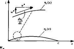
Also, note that this boundary condition can be obtained by requiring that the flow stay tangent to the camberline (see inset to Fig. 5.6). Thus, the slope of the local (total) velocity w*/u* must be equal to the camberline slope:

Подпись: FIGURE 5.6 Thin cambered airfoil at an angle of attack.
image162

w* _ дФ*/дг _drfc и* дФ*/дх dx

Подпись: = УФ*•n = 0
image163

Recalling the definition of the total potential Ф* (Eq. (4.9)), this can be rewritten as

image164

where the normal vector n can be described in terms of the camberline rfc:

Enforcing the small-disturbance assumption (e. g., Wx = Q^a, ЭФ/дх « U*,, and (J„ = Q*, cos a = Qx) reduces this to the same boundary condition as in Eq. (5.29).

When considering a solution, based on a singularity element distribution, the antisymmetric nature of the problem (relative to the x axis, as in Fig. 5.6) needs to be observed. In Section 4.5, both doublet and vortex distributions were presented to model this antisymmetric lifting problem. Traditionally, however, the solution based on the vortex distribution is used, probably because of its easy derivation and “physical descriptiveness.” Also, the boundary condition requiring that the disturbance due to the airfoil will decay far from it (Eq. (4.2)) is not stated since it is automatically fulfilled by either the vortex or doublet elements. Consequently, a model based on the continuous vortex distribution (as shown in Fig. 5.7) is suggested for the solution of this problem. Furthermore, the vortex elements are transferred to the z = 0 plane, following the assumptions of small-disturbance flow where

To demonstrate the basic features of the proposed vortex distribution, consider a point vortex in the x-z plane, located at a point (jc0, 0) with a strength of y0. Here Yo= v(x) ^ at x = x0 in Fig. 5.7. The velocity potential due to this element at a point (x, 2) in the field is then

image165(5.30)

Подпись: (x, z)

Z A

Подпись: Y(x) гУ Un. 0) Подпись:FIGURE 5.7

Vortex distribution based model for the thin lifting airfoil.

The velocity due to a vortex points only in the tangential direction, thus

«•=-£ «’-° <5-31>

where r = V(* – x0)2 + z2. The minus sign is a result of the angle в being positive counterclockwise in Fig. 5.7. In cartesian coordinates the components of the velocity will be (и, w) = qe(sin в, —cos 0), or by simply differentiating Eq. (5.30):

Подпись:u дфур Го z

Эх 2л (x — x0)2 + z2

п.-дфУ0 Го *-*o

dz 2л (x – x0)2 + z2

ZERO-THICKNESS AIRFOIL AT ANGLE OF ATTACK Подпись: (5.33)

Note that if the field point is placed on the x axis, then the velocity above element, normal to the x axis, is

As shown in Fig. 5.7, this problem is being modeled by a vortex distribution that is placed on the x axis with the small-disturbance boundary conditions being fulfilled also on the x axis. The velocity potential and the resulting velocity field, due to such a vortex distribution (between the airfoil leading edge at x = 0, and its trailing edge at x = c) is

Подпись:Ф(х, z) = – f y(*0) tan-1 ) dxо 2л J0 x – Xo>

Here, y(x0) is the vortex strength per unit length at x0.

±r(*)

2

Подпись: u(x, 0±) = lim u(x, z) = z—± 0 Подпись: (5.37)

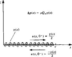
Since the boundary condition will be fulfilled at 2 = 0, it is useful to evaluate the velocity components there. The x component of the velocity above (+) and under (—) a vortex distribution was derived in Section 3.14:

for 0<*<c, and this result is shown schematically in Fig. 5.8. The w component of the velocity at z = 0 can be obtained directly from Eq. (5.36) and is

Подпись: w(x, 0) = -Подпись: _l_ 2л Подпись:image168(5.38)

FIGURE 5.8

image169Tangential velocity and pressure difference due to a vortex distribution.

The unknown vortex distribution y(x) has to satisfy the zero normal flow boundary condition on the airfoil. Therefore, substituting the normal velocity component from Eq. (5.38) into the boundary condition (Eq. (5.29)) results in

ЭФ(х, 0)
dz

image170 Подпись: 0<x<c (5.39)
image171

or

This is the integral equation for y(x). However, the solution to this equation is not unique and an additional physical condition has to be added for obtaining a unique solution. Such a condition will require that the flow leave the trailing edge smoothly and the velocity there be finite

Уф

<00 (at trailing edges) (5.40)

This is the Kutta condition discussed in Section 4.7 which can be interpreted now as a requirement for the pressure difference Ap [or y(x)] to be equal to zero at the trailing edge:

y(x = c) = 0 (5.41)

Once the velocity field is obtained, the pressure distribution can be calculated by the steady-state Bernoulli equation for small-disturbance flow over the airfoil (Eq. (5.16)):

P~P~ = – pQ^uix, 0±) = Tp0« ^ (5.42)

The pressure difference across the airfoil Ap (positive Ap is in the +z direction), where above the airfoil

and at the airfoil’s lower surface

Подпись:Подпись: (5.43)ЭФ

sc-0-)-

is

Ap =Pi~Pu =P

r P-P oo Y

p kpQl V

(5.44)

and the pressure difference coefficient is

ЛС’’2І

(5.44a)

The pressure coefficient with the small disturbance assumption then becomes

SMAL – DISTURBANCE FLOW OVER TWO-DIMENSIONAL AIRFOILS

The strategy presented in Chapter 3 postulates that a solution to the potential flow problem can be obtained by superimposing elementary solutions of Laplace’s equation. Thus, the solution consists of finding the “right” combina­tion of these elementary solutions that will fulfill the zero normal flow boundary condition. Using this approach, in the previous chapter the small-disturbance problem for a wing moving with a steady motion was established. This treatment allowed us to separate the problem into the solution of two linear subproblems namely the thickness and lifting problems. In this chapter the simpler two-dimensional case of both the airfoil with nonzero thickness at zero angle of attack and the lifting zero-thickness airfoil will be solved, by using analytical techniques. These solutions can then be added to yield the complete small-disturbance solution for the flow past a thin airfoil.

4.2 SYMMETRIC AIRFOIL WITH NONZERO THICKNESS AT ZERO ANGLE OF ATTACK

Consider the two-dimensional symmetric airfoil, with a thickness distribution °f Vt(x), at zero angle of attack, as shown in Fig. 5.1. The velocity field will be

x FIGURE 5.1

Подпись: /Подпись:Подпись: QПодпись: Cimage144"Two-dimensional thin symmetric air­foil at zero angle of attack.

obtained by solving the continuity equation:

Подпись: (5.1)У2Ф = 0

with the boundary condition requiring that the flow normal to the airfoil upper (+t?() and lower surface (-»),) be zero:

image145(5.2)

image146

This equation actually states that the sum of the free-stream and the airfoil-induced normal velocity components is zero on the surface

Equation (5.2) is the two-dimensional version of the three-dimensional boundary condition (Eq. (4.30)) and Ф is the perturbation velocity potential. Recall that the boundary condition has been transferred to the z — 0 plane. Also, the boundary condition requiring that the disturbance due to the airfoil will decay far from it (Eq. (4.2)) is not stated because it is automatically fulfilled by the source element.

Because of the symmetry of the problem (relative to the z = 0 plane) the use of a source distribution is selected that inherently has such a symmetric feature. These sources are placed on the x axis from x = 0 to x = c, as shown in Fig. 5.2. The potential of a source distribution can be obtained by observing the potential due to a single source element of strength a0, located at (jc0. 0)

Подпись: 4r Подпись: QQ 2 яг Подпись: (5.4)

The local radial velocity component qr due to this element at an arbitrary point (x, z) is (the tangential component is zero):

In cartesian coordinates this can be resolved into the x and z directions as (и, w) = <7r(sin в, cos в). The same result can be obtained by differentiating Eq. (5.3):

Подпись: дФаа ^Qp x-x0 Эх 2л (x - дс0)2 + z2(5.5)

Подпись:ЭФ oo °p *

yy ———– ————————-

dz 2л (x – x0)2 + z2

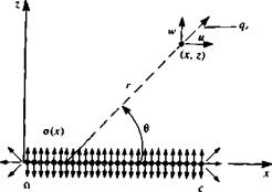
As shown in Fig. 5.2, the airfoil thickness effect is modeled by a continuous o(x) distribution along the x axis. The velocity potential and the resulting velocity field can be obtained by integrating the contribution of the above point elements over the chord (from Jt = 0, to r = c); however, now o(x0) is the source strength per unit length.

-i;

f o(x0) In V(* – *o)2 + Z2 dx0 Jo

(5.7)

ЧЯ

II

3

(5.8)

, ч 1

fc z

(5-9)

w(x, 0±) = lim w(x, z) = ±

z—*±0

Подпись: Ф) 2 Подпись: (5.10)

In order to substitute the velocity component w(x, 0) into the boundary condition (Eq. (5.2)) the limit of Eq. (5.9) at z = 0 is needed. Following the results of Section 3.14,

Подпись: Ua, 0)image147FIGURE 5.2

Source distribution model for the thin symmetric airfoil.

image148

where + is on the upper and – is on the lower surface of the airfoil, respectively. Similarly to the three-dimensional case, this result can be obtained by observing the volume flow rate due to а Ас long element with a strength a(x), as shown in Fig. 5.3. As dz—*0, the flux from the sides of the small element becomes negligible, compared to the flux due to the w(x, 0±) component. The volumetric flow due to a Ajc wide source element is o(x) Ax, which must be equal to the flow rate fed by the two sides (upper and lower) of the surface 2w(x, 0+) Ajc. Therefore,

image150

Substituting Eq. (5.10) into the boundary condition results in

or

image151(5.11)

So in this case the solution for the source distribution is easily obtained after substituting Eq. (5.11) into Eqs. (5.7-5.9):

image152image153image154"(5.12)

(5.13)

(5.14)

It is clear from these equations that the и component of the velocity is

image155 Подпись: (5.15)

symmetric, and the w component is antisymmetric (with respect to the x axis). Therefore the pressure distribution is the same for the top and bottom surfaces and is evaluated at z = 0. The axial velocity component at z = 0 is then

and the pressure is obtained by substituting this into the steady-state Bernoulli equation (Eq. (4.52)):

ЭФ

p-p^=~pQo. — =~pQ^u{x, 0) (5.16)

„ “(*> 0)
G-

Подпись: p-p- ' kpQl Подпись: (5.17)

and in terms of the pressure coefficient

By evaluating the velocity at z = 0±, as in Eq. (5.15), the pressure coefficient becomes

Подпись: =—Г n Jo Подпись:Подпись: ■dx0-2 fc drj,(x0) 1

dx (x – x0)

Since this pressure distribution is the same for the upper and for the lower surface the pressure difference between the upper and lower surface is zero:

Лр=Р/-ри = 0 (5.19)

and the aerodynamic lift per unit width is

L= Apdx = 0 (5.20)

Jo

For the drag force per unit width calculation the contributions of the upper and lower surfaces need to be included using Eq. (4.55):

<5’21)

image156 Подпись: (5.21 a)

Substituting the pressure from Eqs. (5.15) and (5.16) into Eq. (5.21) and observing that the integral of a constant pressure p„ over a closed body is zero yields

It can be shown, using the symmetry properties of the integrand (see Moran,51 pp. 87-88) that the drag is zero:

This result can be obtained directly from the Kutta-Joukowski theorem (Section 3.11). Thus, the symmetrical airfoil at zero angle of attack does not generate lift, drag, or pitching moment. Evaluation of the velocity distribution needs to be done only to add this thickness effect to the lifting thin airfoil problem (as derived in the next section).

To obtain the velocity components from Eqs. (5.13) and (5.14) for points not lying on the strip (0<дг<с, z = 0), the integrals can be evaluated numerically or in closed form for certain simple geometries. However, when the axial component of the velocity or the pressure coefficient is to be determined on the airfoil surface using Eqs. (5.15) and (5.18) it is seen that the integrands become infinite at x=x0 and the integrals are not defined. It is noted that if the thickness is increasing at де = x„, the integrand goes to -« as jc„ is approached from the left and to +» as x0 is approached from the right (e. g., in Eq. (5.15)) and the integrand is antisymmetric in the neighborhood of x = X,).

If the integral in Eq. (5.13) were evaluated at the actual airfoil surface the integrand would not be singular. It is the transfer of the boundary condition to the chordline and the subsequent result that the velocity components on the surface are equivalent to the components on the chordline that has led to the appearance of the improper integral for the surface pressure. It is expected from physical considerations that the surface pressure should be determinable from Eq. (5.18) and aerodynamicists generally agree that the Cauchy principal value of the integral is the appropriate one. The Cauchy principal value of the improper integral

[ f(x0)dx0

Ja

where

Подпись: f(x0) -»oo at x0 = x and a<x<b

is defined by the limit

SMAL - DISTURBANCE FLOW OVER TWO-DIMENSIONAL AIRFOILS

As an example, consider the following integral where the limits can be evaluated in closed form:

= lim [—In (x — x0)|5 £-ln(x0-x)|^+e]

= lim [—In є + In x — In (c – x) + In e] = In ——-

є—*0 С X

Note that in the second integral the sign was changed to avoid obtaining the logarithm of a negative quantity.

In practice, if the integral can be evaluated in closed form the correct Cauchy principal value can be obtained by simply ignoring the limit process as long as the arguments of all logarithm terms are taken as their absolute values.

SMAL - DISTURBANCE FLOW OVER TWO-DIMENSIONAL AIRFOILS Подпись: n — 0, 1, 2,... . Подпись: (5.22)

A frequently used principal value integral in many small-disturbance flow applications is called the Glauert integral (see Glauert,52 pp. 92-93), which has the form

Подпись: or Подпись: t) = ±f/x(c-x) Подпись: (5.23)

Example: Flow past an ellipse. To demonstrate the features of the pressure distribution obtained from this small-disturbance solution consider an ellipse with a thickness of t ■ c at zero angle of attack (Fig. 5.4). The equation for the surface is then

The derivative of the thickness function for the upper (+) and lower (-) surfaces is then

dr) _ t c — 2x dx 2 Vx(c —x)

The velocity distribution on the ellipse is obtained by substituting this into Eq.

(5.12) (note that i) here is ±T),)

u(x,0)=^ff *- -,C. dx о (5.24)

л Jq 2 Vx0(c — jc0) (•* x0)

The integral needs to be evaluated in terms of its principal value. In order to be able to use Eq. (5.22) the following transformation is introduced:

де = ^(1 — cos в) (5.25)

and

dx =~sindde (5.25 a)

which transforms the straight chord line into a semicircle. The leading edge of the

Подпись: 0»Подпись: iWimage159FIGURE 5.4

x Thin ellipse in a uniform flow.

ellipse (дс = 0) is now at 0 = 0 and the trailing edge {x = c) is at в = я. With the aid of this transformation dr)Jdx becomes

dr), _ t______ c – c(l – cos в)__________ cos в

dx 2 lc Ге 1 sin0

yj – (1 – cos 0)^c – – (1 – cos 0) J

Substituting this into the и component of the velocity (Eq. (5.24)),

Подпись: d6 оtQo* Г cos 0p я Jo cos 0O — cos 0

and with the aid of Glauert’s integral (Eq. (5.22)) for n = 1, the axial velocity component reduces to

u{x, 0) = t(5.26)

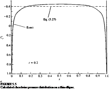
The pressure coefficient thus becomes

C„ = —21 (5.27)

Подпись: c FIGURE 5.5 Calculated chordwise pressure distribution on a thin ellipse.

which indicates that the pressure coefficient is a constant. This result is plotted in Fig. 5.5 and compared with the exact solution obtained by complex variables (Van Dyke53 p. 52). The maximum of |—C„ is well predicted but the solution near the front and rear stagnation points is incorrect. As the thickness ratio decreases the pressure distribution becomes more flat with a smaller stagnation region and therefore the accuracy of this solution improves.

LINEARIZED THEORY OF SMALL – DISTURBANCE COMPRESSIBLE FLOW

The potential flow model was based so far on the assumption of an incompressible fluid. In the case when the disturbance to the flow is small, it is possible to extend the methods of incompressible potential flow to cover cases with small effects of compressibility (e. g., low-speed subsonic flows). To investigate this possibility, the continuity equation (Eq. (1.21)) is rewritten in the form:

Подпись: (4.67)Подпись:— 1 (dp dp dp dp du dv dw ^^ + Ulb + Vty + Wlte)~lb+ty + lk

and the inviscid momentum equations (Eqs. (1.31)) are

du du du du —1 dp

—- 1- и ——- v 1- w —=— —-

dt dx dy dz p dx

dv dv dv dv —1 dp

dt dx dy dz p dy

dw dw dw dw — 1 dp

_ + м__ + и__ + и,_ = — — dt dx dy dz p dz

For an isentropic fluid the propagation speed of the disturbance a (speed of sound) can be defined as

Подпись:,2 З?

dp

and consequently the pressure terms in the momentum equation can be replaced (e. g.,

3P 2^P

dx dx’

in the x direction). Now multiplying the momentum equations by u, v, and w,

respectively, and adding them together leads to

du dv dw 0du 0dv, dw du dv

u — + v— h w —- + U— + V—+W — + uv — + uv —

dt dt dt dx dy dz dy dx

—a[1] ( dp dp dp

~Vu’di + v~dy + w~dd

du dw dv dw

+ uw — + uw —— + vw h vw —

dz dx dz dy

Jl) du _ VW dv

2-у-— 2-у—-

a2 dy a2 dz

image139 Подпись: (4.70)

Replacing the right-hand side with the continuity equation and recalling the irrotationality condition (Eq. (2.12), V X q = 0), results in

Using the velocity potential Ф as defined in Eq. (2.19), and assuming that the free-stream velocity Q„ is parallel to the x axis (thus Q„ becomes {/„), and that the velocity perturbations caused by the motion of the body in the fluid are small, we get

Подпись: dФ ЭФ ЭФ dx У dy У dz (4.71)

Based on these assumptions, the velocity components, in terms of the perturbation velocity potential, are

Подпись: ЭФ dx

Подпись: v Подпись: ЭФ dy Подпись: (4.72)

и = LL +

ЭФ

Подпись: w = ■dz

Assume steady state flow (d/dt = 0), and neglecting the smaller terms in Eq. (4.70), based on Eq. (4.71), this results in

Подпись: = 0/ n2 du dv dw

a2) dx + dy + dz

„ Э2Ф д? Ф Э2Ф (1-МІ)—Ї + —Ї + —Ї = 0

dy2 dz2

Подпись: dx Подпись: (4.73)

By using the energy equation for an adiabatic flow, it can be shown that the local speed of sound can be replaced by its free-stream value and the small-disturbance equation becomes

For time-dependent flows the dp/dt term in Eq. (4.70) needs to be evaluated

Подпись: 0І I I ' ' і l_ 0.0 0.2 0.4 0.6 Подпись:

image142

which indicates that at higher speeds the lift slope is increasing as shown by Fig. 4.14. Also, note that according to Eq. (4.74) the x coordinate is being stretched as the Mach number increases and therefore the results for M = 0 and M > 0 are for wings of different aspect ratio.

Based on the results of Fig. 4.14 (for a two-dimensional airfoil), for small-disturbance flows the potential flow based models of this chapter are applicable at least up to = 0.6.

THE VORTEX WAKE

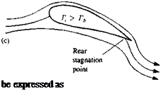
The analysis followed up to this point suggests that by using distributions of the elementary solutions of Laplace’s equation, the problem is reduced to finding a combination of these elements that will satisfy the zero normal flow boundary condition on solid surfaces. However, as in the case of the flow over a cylinder (Section 3.11), the solution is not unique and an arbitrary value can be selected for the circulation Г. This problem is illustrated for the airfoil in Fig. 4.11, where in case (a) the circulation is zero. In case (b) the circulation is such that the flow at the trailing edge (T. E.) seems to be parallel at the edge. In case (c) the circulation is larger and the flow turns downward near the trailing edge (this can be achieved, for example, by blowing). W. M. Kutta (German mathematician who was the first to use this trailing edge condition in a theoretical paper in 1902) suggested that from the physical point of view, case (b) seems to result in the right amount of circulation. The Kutta condition thus states that: The flow leaves the sharp trailing edge of an airfoil smoothly and the velocity there is finite. For the current modeling purposes this can be interpreted that the flow leaves the T. E. along the bisector line there. Also, since the trailing edge angle is finite the normal component of the velocity, from both sides of the airfoil, must vanish. For a continuous velocity, this is possible only if this is a stagnation point. Therefore, it is useful to assume that the pressure difference there is also zero

Дрт. Е = 0 (4.63)

Additionally if the circulation is modeled by a vortex distribution, then this can

FIGURE 4.11

Подпись: be expressed as Possible solutions for the flow over an airfoil: (a) flow with zero circulation; (b) flow with circulation that will result in a smooth flow near the trailing edge; (c) flow with circula­tion larger than in case (b).

Подпись: (4.63a)Yt. e. — 0

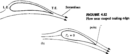
For a cusped trailing edge (where the angle is zero, as in Fig. 4.12), Eq. (4.63) must hold even though the trailing edge need not be a stagnation point.

Next, consider the lifting wing of Fig. 4.9. As was shown in the case of the cylinder, circulation is needed to generate lift. Assume that the vortex distribution that is used to model the lift is placed on the wing as the bound vortex Yy(x, y), where the subscript designates the direction of the circulation vector. But, according to Helmholtz’s theorem a vortex line cannot begin or end in the fluid, and any change in yy{x, у) must be followed by an equal change in yx(x, y). Consequently, the wing will be modeled by constant – strength vortex lines, and if a change in the local strength of yy(x, y) is needed then an additional vortex line will be added (or the vortex line is bent by 90°) such that

Подпись: dyx(x, y)_ dyy(x,y) ду Эх

image136,image137

(4.64)

This condition can also be obtained by requiring that the flow above the wing be vorticity free. Thus the vortex distribution induced velocity at a point slightly above (z = 0+) the wing is

u(x. 0+) = (4.65a)

»<*,»+)(4.656)

In order than the flow resulting from this vortex distribution be vorticity free we require:

which is exactly the same result of Eq. (4.64).

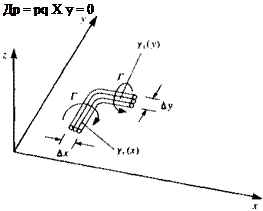
The physical meaning is that any change in vorticity in one direction must be followed by a change in a normal direction (as shown in Fig. 4.13, where the wing and the vortex lines are in the x-y plane). Consequently all vortex lines must be either infinitely long lines or closed vortex rings. In the case of the wing this means that the lifting vortices (bound vortex) cannot end at the wing (e. g., at the tip) and must be extended behind the wing into a wake. Furthermore, for a lifting wing a starting vortex is created that may be located far downstream.

Next, the wake shape must be considered. If the wake is to be modeled by a vortex sheet (free vortex sheet) then from physical considerations it must be different from the bound circulation by not creating loads. The pressure difference across the sheet is obtained by a generalization (with vector notation) of Eq. (4.59c), and if there is no pressure difference across the vortex sheet then

Подпись: Др = pq X у = 0 FIGURE 4.13

Method of terminating a bound (lift­ing) vortex; since vortex lines cannot end in a fluid, the bound vortices are turned back parallel to the free stream.

or

q X y = 0 (4.66)

where y = (y*, Yy> Yz)- This means that the velocity on the wake must be parallel to the wake vortices.

This consideration will be very helpful when proposing some simple models for the lifting wing problem in the following chapters.

A small disturbance approximation applied to the wake model results in

О» X y = 0 (4.66a)