Category BASIC AERODYNAMICS

Doublet (or Dipole)

Doublet (or Dipole) Подпись: Figure 4.11. Source-sink pair.

A doublet (or dipole) is defined as a source-sink pair for which the separation dis­tance h ^ 0, whereas the absolute value of the strength, Л, increases such that the

product Q = НЛ remains constant. What this means is that the strength becomes large and the separation distance becomes infinitesimal. Thus, by definition:

Comparing the two expressions for the velocity potential, f(r) = g(0) = constant. Set­ting the potential function to be zero at 0 = n/2 makes the constant of integration zero, so that:

Подпись: (4.38)Q cos 0 2n r

Подпись: and ф DQ x

2n x2 + y2 for polar and rectangular coordinates, respectively. The subscript D denotes a doublet.

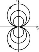
Again, Eqs. 4.37 and 4.38 can be shown to be solutions of Laplace’s Equation by direct substitution. The flow pattern generated by the doublet at the origin, with the source and sink placed on the x-axis, is shown in Fig. 4.13. The flow direc­tion is established by the source being placed on the left side and the sink on the right side.

If the source and sink were located initially on the y-axis instead of the x-axis, the circular streamlines would have been symmetric about the hori­zontal axis instead of the vertical axis, as depicted in Fig. 4.13, and the axis of the doublet then would be vertical. The doublet shown in the figure is said to have a horizontal axis, meaning that the original source and sink were located on the x-axis.

Four elementary solutions now have been developed and they are collected and tabulated in Table 4.1. It is assumed in this discussion that the source, vortex, and doublet each are located at the origin of coordinates. If it is desired to locate any of them away from the origin, the appropriate expression for the stream function or the velocity potential can be obtained readily from the equations given herein by a simple shifting (i. e., linear transformation) of the appropriate coordinates. It remains to superimpose combinations of these simple Laplace’s Equation solutions to produce solutions for more complicated and interesting flow fields. We also are looking for a way to address the singular points that arise in the elementary solu­tions. Clearly, these cannot correspond to physically real conditions because, for example, there cannot be point sources with infinite velocity or vortex points with infinite strength.

Doublet (or Dipole)

Figure 4.13. The doublet (dipole) with vertical axis of symmetry.


Doublet (or Dipole)

Ф

W

Cartesian

Polar

Cartesian

Polar

u

v

Vr

Freestream at a

V„(x cos a + y sin a)

V r cos(8 – a)

V„(y cos a + x sin

a)

V r sin(8 –

a) V cos a

V sin a

V cos (8 – a)

V sin (a – 8)

Source-sink

ln(*2+^

+A

2П ln^)

±Л tan-‘ f У1 2n ^ x 1

T^8

2n

±Л x

±Л y

±Л

0

2n (x2 + y2)

2n (x2 + y2)

2nr

Doublet

К X

к cos 8

к y

к sin 8

к y2 — X2

к 2 xy

к cos 8

к sin 8

2n (X2+ y2)

2n r

2n (X 2 + y2)

2n r

2n (x2 + y2)2

2n (x2 + y2)2

2n r2

2n r2

Vortex

-f tan-‘ f У1

2n ^ x 1

– s8

4П ln(*2+y2)

Г

2n ln^)

Г y

Г x

0

Г

2n (x2 + y2)

2n (x2 + y2)

2nr

Source-Sink Pair

The doublet solution is generated by a superposition of a source and a sink. It is such a basic element in the superposition of complex flows that here, it is considered a fourth-elementary flow.

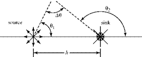
Consider a source-sink pair of equal strength placed a distance h apart along the x-axis, as shown in Fig. 4.11. For convenience, assume that the left singularity (i. e., the source) is located at the origin of coordinates.

At a Point P, which is arbitrarily located, ¥, = ^0, and y2 = -^02 by

2n 2n

applying Eq. 4.31. Superposing (adding) these two stream functions results in a new stream function that also satisfies the Laplace’s Equation and represents a new, more complicated flow field. Thus,

Подпись: (4.36)¥ = ¥i + ¥2= 2П(01-02) = 2П(-Д0)

because 01=л-Д0 and 02 =n-(n-0,-A0).

Source Flow

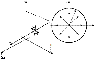
Source flow is flow that is assumed to emanate from a point source. In two­dimensional flow, a line source of infinite length pierces the x-y plane at a point (Fig. 4.9a). This point source in the x-y plane corresponds to outflow from the axis of a cylinder (Fig. 4.9b). In three-dimensional flow, a point source corresponds to out­flow from the center of a sphere (see Chapter 7). Source flow is emitted in a purely radial direction; there is no tangential component of velocity. Thus, the streamlines are all straight lines originating at a point.

Assume two-dimensional planar flow and consider a point source at the origin of coordinates. Let Л be defined as the volume flow rate from the source per unit time per unit depth out of the page. The magnitude of this quantity is the “strength” of the source, which can be adjusted as necessary to match boundary conditions during analysis. If Conservation of Mass is to be satisfied, then for any circle of arbi­trary radius r, about the origin (Fig. 4.9c),

Source Flow Source Flow Подпись: X

рЛ = mass flux out of source = p(2nr)(1)ur ^ ur =2~>

Figure 4.9. Point source.

where 2n is the circumference of the circle of radius r and the product of this with unity normal to the x-y plane yields the area through which the outflow occurs. By defini­tion, the circumferential velocity u0 = 0. Notice that continuity requires that the radial velocity be proportional to 1/r so that at the source (r = 0), the velocity is infinite. This singularity is not troublesome in constructing flows by super position, as shown later.

Source Flow Подпись: constant

Integrating the velocity components yields the following in polar coordinates (i. e., the most convenient coordinates for this flow):

Подпись: ¥ = g(0) + constant.n dy

u0= 0 = —-—

0 dr

Source Flow Source Flow Подпись: ф = I dr = — lnr + f (0) + constant J 2nr 2n Ф = g(r) + constant.

Comparing the two expressions for y, it follows that f(r) = 0. The constant of inte­gration may be set to zero for convenience. Similarly,

Comparing, f(0) = 0 and the constant of integration may be set to zero. Summarizing for polar coordinates:

Подпись: (4.31)Подпись: (4.32)у = — 0
2n

ф =— lnr
2n

and converting to rectangular coordinates:

Л – i

y s = 2Пtan

ф8 = 2Пln ( + /),

where the subscript s designates a source.

Again, substitution shows that Eqs. 4.31 and 4.32 both satisfy the Laplace’s Equation. Considering a circular path enclosing the origin, the circulation around that closed path is zero because there is no component of velocity tangential to the path (u0 = 0). Thus, by Stokes’ Theorem, the source flow is an irrotational flow.

A sink is simply the opposite of a source; that is, the strength Л is negative instead of positive. The radial velocity is inward (negative ur) and the fluid flows into the origin rather than being emitted from the origin. Eqs. 4.31 and 4.32 apply, with a change in sign.

Vortex

The elementary solution called a vortex was encountered in Example 4.3, where it was shown that a physically possible flow with circular streamlines must have a
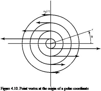
tangential velocity that varies inversely as the distance from the center if the flow field is to be irrotational. Figure 4.10 illustrates such a flow field. Thus, ue = K/r and ur = 0. It was not possible to state previously whether the flow is rotational at the exact center. The answer to this question had to await development of the concept of circulation. Because this now is accomplished, we apply the definition of circulation by taking the line integral around a closed path, which is a circle of arbitrary radius r centered at the origin. Then:

2n 2n – jr

Г = – Jv. ds = – J u0 (rd0) = – J K(rdQ)

0 0 r

and, integrating:

Г

Г = -2nK ^ K =——- .

Подпись:

Подпись: Figure 4.10. Point vortex at the origin of a polar-coordinate system.

2n

Next, we appeal to Stokes’ Theorem, Eq. 4.10—namely:

r = – J Vds =-JJ (Vx V)-ndS.

C S

Take the surface integral to be over the surface enclosed by the circle and lying in the x-y plane, so that dS in Eq. 4.10 is an element of an area of a circle and the unit vector perpendicular to the surface in the x-y plane is n = k. Furthermore, in the x-y plane, the curl of the velocity vector, V x V, is a vector with a single component per­pendicular to the plane and with a magnitude IV x VI. Then, it follows that:

-Г = 2пК = jj (V x V) • ndS = jj (| V x VI)k • kdS = JJlVx V | dS

s S S

Because within the double integral, the dot product k* k is unity.

Consider now a small circle enclosing the origin. The circulation on the path enclosing this circle is unchanged because for this flow, Г does not depend on r. If the area is small, then the magnitude IV x VI may be assumed to be an average value over the area, and this constant quantity may be taken through the surface integral. Thus, the previous equation becomes:

-Г = 2nK = JjlVx Vi dS = IVxVi jj dS = IV x Vi (nr2).

S S

From this, it follows that:

IVxVI = 2^, r2

which indicates that as r ^ 0, the curl of the velocity vector (i. e., the vorticity) becomes infinite.

The conclusion drawn from this application of Stokes’ Theorem is that a vortex is irrotational everywhere except at the origin, where it is rotational and, in fact, the vorticity is infinite. Note that for any closed curve that does not enclose the origin, the circulation is zero. For any closed curve that does enclose the origin (regardless of shape), the circulation is a constant.

Source Flow Подпись: Г. 2nr'

It is demonstrated in Example 4.3 and Eq. 4.33 that for a point vortex:

Подпись: ue Ur Подпись: dr і dy r ЗЄ Source Flow

Then:

where c1 and c2 are arbitrary constants. Comparing, ДЄ) = 0 and the constant of integration may be set equal to zero. A parallel development yields the velocity potential.

Thus, in polar coordinates for a point vortex at the origin:

Подпись: (4.34)w,, = — lnr 2n

Подпись: Ф V =2te’

whereas in Cartesian coordinates:

Подпись: /  Подпись: (4.35)Г -1

—- tan 1

2п

where the subscript v denotes a vortex.

The (constant) circulation, Г, around the point vortex is termed the strength of the vortex because the tangential velocity is directly proportional to this arbitrary constant. Again, substitution demonstrates that Eqs. 4.34 and 4.35 are solutions to the Laplace’s Equation.

Elementary Solutions

Recalling the findings of the last section, we proceed to construct a set of elementary solutions to Laplace’s Equation. The corresponding stream-function and velocity potentials are determined, which then form the basis for a powerful problem-solving technique using superposition of the elementary solutions. We start with the simplest and proceed to the more complex flow patterns as we are guided by both physical and geometrical considerations.

Uniform Flow

Elementary Solutions

For uniform flow, u = VM, v = 0. Thus,

Because f(x) must be zero, the x-axis has been made the zero streamline (i. e., at y = 0, у = 0), so that the constant of integration is zero. The subscript UF designates uni­form flow. Thus, by a similar procedure, ф№ = V^x.

Collecting the results, in Cartesian coordinates,

Iу uf = V~ y (4.29)

1ф№ = Vx.

For many problems, the polar-coordinate form is useful. In this case,

IVUF = V~r sin 0 (4.30)

1фот = V r cos 0.

The student should verify that uniform flow satisfies continuity and is irrotational and that Eqs. 4.29 and 4.30 both satisfy the Laplace’s Equation on substitution.

In what follows, the uniform flow usually is taken as coincident with the x-axis. The results may be extended to uniform flow at an arbitrary angle by letting u = Vx cos a and v = Vx sin a.

Solving Laplace’s Equation

The Laplace’s Equation V2 ф = V2y = 0, Eq. 4.24, must be solved for the single depen­dent variable, either ф or y, subject to the appropriate boundary conditions for the problem under consideration. This ensures that the solution describes the proper physical reality. The second-order Laplace’s Equation requires two such boundary conditions. For the aerodynamic problems, these are (1) the disturbance due to the presence of the body in the flow must die out far away from the body in the freestream; and (2) the velocity component normal to the body surface must be zero because the body is a solid. These two boundary conditions are expressed in terms of the scalar functions, as follows:

far from the body, u = — = — = V ; v = 0

dx dy

and

at the body surface, ^= 0, dn ds

where n and s are the directions normal and tangential to the body surface, respec­tively. In other words, the flow must be tangent to the body surface.

The Laplace’s Equation has a property that may be used to simplify enor­mously the solution—namely, that the equation is linear. Linearity means that in the equation, there are no products or terms taken to a power that contains the

Подпись:Подпись: эУПодпись:Подпись:are not. It

also means that no transcendental functions of the dependent variable appear. This linearity property means that superposition of solutions may be used. Thus, if ф1 and ф2 are each a solution to the Laplace’s Equation, then the linear combination ф = аф1 + Ьф2 (where a and b are arbitrary constants) also is a solution.[15] This may be verified by direct substitution into Laplace’s Equation. Of course, the appropriate boundary conditions must be satisfied by solution ф.

The far-reaching significance of superposition is that simple (or elementary) flow solutions may be added together to form solutions corresponding to more com­plicated flows. This means that it may not be necessary to solve Laplace’s Equation to carry out the solution strategy described previously. A much simpler strategy can be followed. Consider the following steps:

1. Specify the velocity components for simple flows by inspection (e. g., for a uni­form flow, the velocity components are u = VM and v = 0).

2. Integrate to find ф or у for each simple flow as in Examples 4.6 and 4.8. The con­stant of integration may be set equal to zero or to any convenient value because the final variables of interest are the velocity components, the derivatives of ф or у, and the constant of integration drops out.

3. Superpose (add) the simple (elementary) solutions for ф or у corresponding to these simple flows.

4. Differentiate this superposed solution to obtain the velocity components for a new, more complicated flow and then use these components to determine the velocity magnitude.

5. Use the Bernoulli Equation to solve for the magnitude of the corresponding static pressure.

The next section explains how elementary solutions to the Laplace’s Equation for simple flows are found. These elementary solutions then are superposed in Sec­tion 4.6 to construct more complex and realistic flow-field solutions.

Solving the Conservation Equations

In this section, we continue the quest started in Section 4.3 for special forms of the governing equations that can be solved using standard mathematical tools. We found that a special form of the momentum equation could be solved by simple integration leading to the powerful Bernoulli Equation. We continue our examination of the governing equations for the case of incompressible steady flow.

Laplace’s Equation

Return now to the continuity equation, Eq. 3.52, which is one of the defining equations for a two-dimensional incompressible-flow problem. The continuity equation may be written in terms of a single dependent variable—either the velocity potential or the stream function—provided that the flow is irrotational. To show this in both

Cartesian and polar coordinates, write the continuity equation in vector form, as in Eq. 3.52—namely, V-V = 0. Now, for an irrotational flow, V = Уф, and substituting this into the continuity equation yields:

Подпись: (4.24)V – (Уф) = У[13] 2ф = 0.

Eq. 4.24 is Laplace’s Equation, an equation that appears in many fields including heat transfer and electrodynamics. Eq. 4.24 in Cartesian coordinates is:

Подпись: (4.25)дх2 ду2

1 дф+1 дФ.

r Э0[14] r dr

Подпись: у2ф=дА + ^^ + ^ї. = о. y dr2 -2 3rt2 ~ 0- Подпись: (4.26)

and in polar coordinates, Laplace’s Equation is:

These two equations each represent a single equation in terms of a single dependent variable, which suggests that a solution is possible.

Regarding the stream function, recall that for irrotational flow, it follows from

Eq. 4.3 that — = — and, from the definition of the stream function, Eq. 4.11, that:

ду Эх

дш, дш

и = —^ and v = -—!-.

ду дх

Substituting the second relation into the first yields:

їш + ЇШ ш = о, (4.27)

дх2 ду2

which is the Laplace’s Equation in Cartesian coordinates.

A parallel development for the stream function shows that it satisfies the Laplace’s Equation in cylindrical coordinates—namely:

Подпись: (4.28)д2 ш+1 д! ш+1 эу=0

дг2 г2 д02 r дг ■

Notice that the original set of three simultaneous partial-differential equations describing a two-dimensional, incompressible, inviscid flow was replaced by the Laplace’s Equation and a scalar equation, the Bernoulli Equation. This represents a considerable mathematical advantage because it is not necessary to deal with any vector variables. A strategy for predicting the pressure distribution in a steady two­dimensional inviscid, irrotational flow then is as follows:

3. Knowing the velocity components, determine the magnitude of the local flow velocity.

4. Use the Bernoulli Equation to solve for the static pressure at any point in the flow field. The stagnation pressure is known or can be measured for a given flow.

Special Solutions of the Conservation Equations

Certain special solutions of the basic equations describing an incompressible flow are of great value in applications. We start by looking for an important integral of the equations that provides information regarding the connection between the local pressure and flow speed.

From Chapter 3, the defining equations in Cartesian coordinates for a two­dimensional planar, incompressible, inviscid steady flow are:

continuity: — + — = 0 (3.52)

dx dy

du du dp,

x-momentum: ри—+ pv— = – A – + obx

dx dy dx x

y-momentum: pw-^- + pv dТ = -^T + pby, (3.70)

dx dy dy y

where the density is constant and a body-force term was added to Eq. 3.2 as two components bx and by to make a point (the body-force term is shown to be negligible in most aerodynamics applications and later dropped). The task, then, is to solve this set of three simultaneous partial-differential equations for the three unknowns u, v, and pressure p. In fact, this task is not as difficult as it may first appear.

Consider first the momentum-conservation equations. Rather than write them as two-component equations, as previously, write the vector equation, Eq. 3.66, for a steady, two-dimensional, inviscid flow. Then, Eq. 3.66 becomes:

dV dV „ ,.л,,

pu— + pv— = – Vp-pb. (4.16)

dx dy

The body force is assumed to be the gravity force acting in the downward direction (i. e., the y direction in two dimensions); this is the usual case. Thus, b=g=| g IJ = – gj, where g is the acceleration due to gravity and j is the unit vector in the y-coordinate (upward) direction. Because rectangular coordinates are used, Eq. 4.16 can be written in a more compact vector form as:

p(V-V)V=-Vp-pg. (4.17)

The objective is to directly integrate this form of the momentum equation. Integration can be carried out in a straightforward way under two different assumptions, each of which leads to the same final form of integrated equation. However, the equations actually apply to different sets of physical conditions. Both
assumptions are demonstrated here to emphasize the difference in the applica­bility of the resulting integrated equations. Because the full vector form of the momentum equation is used, the two approaches that follow also are valid in three dimensions.

The first approach is to integrate Eq. 4.17 along a streamline; in this case, the flow may be rotational. The second approach considers integration along any arbi­trary path through the flow field; however, the flow then must be irrotational as demonstrated here.

1. Integration along a streamline:

First expand Eq. 4.17 in standard vector notation, as follows:

P(V»VXm + vj) = – zjp і – – У j + pgj

Подпись: du du dv dv u-—+ v — і + P u-—+ v— dx dy _ dx dy _ Подпись: PПодпись: j = JjL і j dx dp. .

ayJ+pgj.

Special Solutions of the Conservation Equations Подпись: -dpdx -dpdy + pgdy, dx dy Подпись: (4.18)

Consider now a general incremental displacement vector ds = dx і + dy j. Taking the vector-dot product of ds with the vector-momentum equation results in:

which is valid along any line in the flow field. Focus on the square bracket on the left side of this equation. Now, require that the length ds is not any arbitrary length but rather is a length ds along a streamline. Recall from the definition of a streamline that a certain relationship between u and v must hold along a stream­line—namely, that:

— = v ^ udy = vdx. dx u

Подпись: P Special Solutions of the Conservation Equations

Use this relation in the second and third terms within the square bracket. Substi­tute (udy) for (vdx) in the second term and (vdx) for (udy) in the third term. The result is:

Now, from calculus, if u = u (x, y), then:

, du, du,

du = — dx +—dy. dx dy

The same thing is true for v(x, y) and p(x, y). Thus, the full equation, Eq. 4.18, may be rewritten along a streamline as follows:

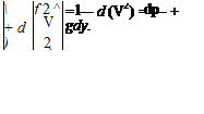
Подпись: But and p [udu+vdv] = – dp + pgdy udu = d(u2/2), vdv = d(v2/2),

Подпись: d Подпись: u Special Solutions of the Conservation Equations Подпись: (4.19a)

so that on dividing through by p, Eq. 4.18 finally becomes:

In Eq. 4.19a, the quantity V is the magnitude of the velocity vector (sometimes referred to as the speed) and the square of V is equal to the sum of the squares of the orthogonal velocity components.

Eq. 4.19a is set aside to derive this same equation in another way. The equation then is integrated. Note that Eq. 4.19a is easy to integrate if the density, p, and the gravitational acceleration are constant.

2. Integration throughout the flow field (irrotational flow only):

Special Solutions of the Conservation Equations Подпись: Vx (VxV).

The starting point is again Eq. 4.17. Begin by using a standard vector identity that states:

Подпись: pV Special Solutions of the Conservation Equations Подпись: = ~VP + pgj>

Now, for an irrotational flow, the curl of the velocity vector, VxV = Z, is zero by definition. Hence, for an irrotational flow, the left side of Eq. 4.17 simplifies and the equation becomes:

Подпись: p Подпись: ъ_( dx у 2 Подпись: , d f V2 +dy IT Подпись: dy Подпись: -dpdx-dpdy + pgdy. dx dy

where again, V is the magnitude of the velocity vector. Taking the vector-dot product of this equation with an arbitrary line segment ds = dxi + dyj yields Eq. 4.17 in the following form:

Special Solutions of the Conservation Equations Special Solutions of the Conservation Equations Подпись: (4.19b)

Again using the basic ideas of calculus, this may be written as follows:

Eqs. 4.19a and 4.19b are identical but arise from different assumptions. Notice that under either assumption, the two partial-differential momentum equations in component form have reduced to a single equation, Eq. 4.19a or 4.19b, which may be integrated easily providing that the density and gravity are constant.

The Bernoulli Equation

Recall that the flows considered here are incompressible. It follows that:

Подпись: 1 p j dp.

Special Solutions of the Conservation Equations Подпись: (4.20)

Also, assume that the magnitude of the acceleration due to gravity, g, is a constant (to be justified later). Then, integrate Eq. 4.19 as follows:

The integration follows directly because each integral operation simply undoes the differential operation that follows it. Eq. 4.20 is a simple algebraic equation. Consid­ering Eq. 4.19 to be derived along a streamline as in Eq. 4.19a, the most that can be said is that the sum of the three terms in Eq. 4.20 is equal to a constant at any point along a particular streamline. It is not a requirement that this constant is the same among streamlines. However, if irrotationality is assumed as in Eq. 4.19b, then the constant must be the same on every streamline and, hence, throughout the flow field.

Taking two points in the flow field, either along a streamline or in an irrotational flow field, Eq. 4.20 states:

1 T/2 1 T/2

2PV1 +Р1-ВУ1 = 2PV2 + —2 – gy2.

In ordinary aerodynamic problems, the extent of the region of interest around an air­foil or fuselage is not large in the vertical (y) direction, so that (y1 – y2) is small. (This may not be true for a dirigible with large dimensions in the vertical direction!) Thus, in the usual problems of flows around flight vehicles, the gravity-force contribution is negligible and this term, henceforth, is neglected. Eq. 4.20 is written as follows:

1 2

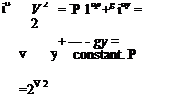
p + 2 pV2 = constant = p o. (4.21)

Eq. 4.21 is the celebrated Bernoulli Equation.[12] It is emphasized that this equation may be used only for an incompressible flow. Serious errors have been made by forgetting this important limitation. It was the incompressible-flow assumption that

allowed the term 1 — to be written as — 1 dp and the integration of the exact dif – PP

ferentials followed directly. If the flow is compressible, other similar but somewhat more complicated equations relating the flow variables may be derived, as accom­plished later. However, for emphasis, the Bernoulli Equation as derived here may not be used to make calculations for a compressible flow.

Now, examine the Bernoulli Equation. If two points are taken in an irrotational flow field, the equation states that the sum of the static-pressure term and the term pV2/2 is equal to the same constant at those two points. If the second point is taken to be a location where the velocity is zero, the pressure term alone appears in the sum at that point. This term is the pressure when the velocity is zero (i. e., when the flow is brought to rest or stagnates), and this pressure is give a special name and
symbol: stagnation pressure = po = pressure where the flow velocity is zero. This ref­erence pressure often is referred to as the total pressure (because it is evaluated by summing two terms) or the “total head” (because pressure is sometimes measured as the height of a liquid column).

Recalling the two different approaches in the derivation of the Bernoulli Equation, it follows that if a flow is rotational (e. g., within a boundary layer), then the stagnation pressure is constant along any streamline within the boundary layer, but the constant is not the same value among streamlines. If a flow is irrotational, the stagnation pressure is the same everywhere in the flow field.

All of the terms in the Bernoulli Equation have the units of pressure because:

slug

" ft2"

lbf s2

" ft2"

‘ lbf"

_ ft3 _

_ s2 _

ft4

_ s2 _

_ ft2 _

Thus, each term in the Bernoulli Equation can be given a descriptive pressure name as follows:

p = static pressure = the pressure in a flow field that would be measured by an instrument moving with the same velocity that the flow is moving at the point in question

рУ2/2 = dynamic pressure = the “pressure” due to fluid motion po = stagnation pressure = the pressure at some point in the flow where the velo­city is zero, as at the stagnation point at the nose of an airfoil or vehicle

These three definitions are fundamental and appear throughout this book. The defi­nitions must be committed to memory and a clear understanding of their physical meaning is vital.

Static pressure at a point must be measured in a way that does not disturb the flow because if the flow is locally slowed or accelerated by the measuring device, then a true measurement cannot be made. One way to measure the static pressure of a flow in a wind-tunnel test section, for example, is to make a small hole (i. e., a static-pressure tap) in the wall of the test section (Fig. 4.6a). The hole should be smooth and small enough to ensure a local measurement, and it is connected by tubing to some suitable pressure-measuring device. Of course, there is a boundary layer growing on the test-section wall, but it is shown in Chapter 8 that the variation of static pressure through this boundary layer in a direction normal to the wall essen­tially is zero. Hence, the static pressure as measured at the wall is that of the external,

Подпись: flow ►Подпись:Подпись: Figure 4.6. Measurement of static pressure.Special Solutions of the Conservation Equationsstatic port

(b)
undisturbed flow at a particular streamwise station. If the static pressure is not con­stant across the test section, a local measurement in the flow may be made by using a static-pressure probe (Fig. 4.6b), which is a small tube aligned with the flow and streamlined at the upstream end so as to produce as small a flow disturbance as poss­ible. A static-pressure tap is made in the tube wall several diameters downstream of the front of the probe to allow any local-flow accelerations around the nose to die out. This pressure tap is connected to a suitable pressure-measuring device.

The dynamic pressure cannot be measured directly because it is not a physical quantity but rather is only a variable having the units of pressure. The dynamic pressure can be measured indirectly as the difference between the stagnation pressure and the static pressure.

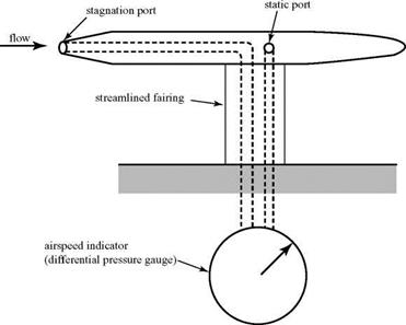
The stagnation pressure in a flow can be measured by using a stagnation-pressure probe (also called a pitot probe or a total head probe), shown in Fig. 4.7. This is simply an open-ended tube aligned with the flow and connected to a pressure-measuring device, which effectively “dead-ends” the tube. The oncoming flow slows and then comes to a rest at the entrance to the tube. The resulting stagnation pressure can be measured by means of an aneroid device or a liquid column.

The simultaneous measurement of stagnation and static pressure allows for the determination of flow velocity through the use of the Bernoulli Equation (providing, or course, that the density is known or can be measured).

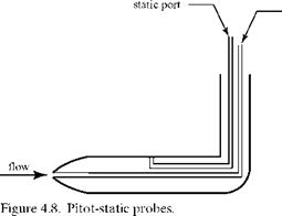
This would be a truly local measurement only if the static and stagnation-pres­sure probes were located close to one another. Hence, they are often combined into one instrument, called a pitot-static probe (Fig. 4.8).

The differential (i. e., stagnation minus static) pressure is most often measured by using such a probe because this is more accurate than measuring each pressure independently and then finding the difference between the two values. Again, the static-pressure tap must be located far enough from the nose of the probe that the flow has returned to essentially undisturbed conditions.

The stagnation pressure exists as a physical reality anywhere that the flow is brought to rest (e. g., at the end of a pitot probe or at the stagnation point on an airfoil or wing). However, the stagnation pressure can be defined at any point in the flow field, whether or not the flow there is at rest. Thus, for purposes of calculation, the flow can be thought of as being brought to rest at any convenient point in the flow (whether or not it is physically at rest there) by means of an “imaginary” pitot probe, if this is helpful during the solution of a problem.

It is often convenient to express a physical pressure in terms of a nondimen­sional ratio called the pressure coefficient:

Подпись: 2 ’Special Solutions of the Conservation Equations

Special Solutions of the Conservation Equations
Подпись: to pressure gauge

(4.22)

Special Solutions of the Conservation Equations

Special Solutions of the Conservation Equations

where p is the local static pressure in question and the subscript ^ refers to values of static pressure, density, and velocity in the undisturbed freestream. The density usually is written without a subscript in material pertaining to incompressible flow because for incompressible flow, the density is constant everywhere in the flow field. The dynamic pressure in the denominator of Eq. 4.22 always is formed with the freestream values of velocity and density (which are constants) rather than with local values, which vary throughout a flow. Expressing a pressure in coefficient form conveys considerably more information than just a quoted pressure magni­tude because knowledge of the nondimensional coefficient value allows the predic­tion of the pressure magnitude in a corresponding flow that could have a different freestream velocity and/or freestream static-pressure level.

This definition of the pressure coefficient also is valid for a compressible flow (with the density now carrying an “infinity” subscript), including supersonic flow. Care must be taken in examining plots of chordwise pressure distribution on airfoils
because the convention is to graph the pressure-coefficient ordinate as negative upward. Notice that the pressure coefficient can be either positive or negative, depending on the relative values of the local and freestream static pressures. This is in contrast to the absolute pressure, which never can be negative.

Special Solutions of the Conservation Equations Special Solutions of the Conservation Equations Подпись: (4.23)
Special Solutions of the Conservation Equations

In the case of incompressible, inviscid flow in which the Bernoulli Equation holds and the stagnation pressure is constant everywhere, the pressure coefficient may be written as:

V2

Pressure distributions often are tabulated as the ratio — for incompressible flows.

Special Solutions of the Conservation Equations

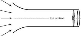
EXAMPLE 4.9 Given: Air is drawn from the atmosphere at standard sea-level con­ditions (p = 1.225 Kg/m3,p = 1.013 x 10⁵ N/m2) into a wind tunnel by means of a fan at the discharge end (see illustration). It is known that at a certain fan speed, the test-section velocity is 60 m/s. Assume the flow to be steady, incompressible, and inviscid.

Required: Predict (a) the pressure at the stagnation point of a model in the test section, and (b) the static pressure in the test section with the model removed.

Approach: Because the flow is at low speed (and assumed to be incompressible), use the Bernoulli Equation.

Solution: (a) Consider any fluid particle suitably far from the wind-tunnel entrance so that it is initially in the atmosphere at rest and then is sucked into the test section by the inflow. The path of this particle is a streamline along which the stagnation pressure is constant. Far from the entrance, the pressure of the air at rest is atmospheric pressure, so that the stagnation pressure along that streamline is atmospheric pressure. The same is true for any streamline because the flow is assumed to be inviscid and, hence, irrotational. Thus, when the fluid particle is brought to rest at the stagnation point of the model, the pressure there is the stagnation pressure along the stagnation streamline, which in this wind tunnel is equal to the atmospheric pressure. No calculation is necessary.

(b) Consider any streamline and imagine bringing the flow to rest somewhere in the empty test section. The stagnation pressure there is atmospheric pressure, as noted in (a). Apply the Bernoulli Equation at this point:

P + 1pV2 = Po =1.013 x 105 = p +1(1.225)(60)2.

Solving, the static pressure in the empty test section is 9.915 x 10⁴ N/m2.

Appraisal: The static pressure in the test section must be less than the stag­nation (atmospheric) pressure, as indicated by the answer. Careful thought is necessary in this problem to correctly identify static and stagnation pressure (contrast the role of atmospheric pressure in this problem with Example 4.10). In (b), the ability to “imagine” the flow being brought to rest in the test sec­tion—even though there is no stagnation point physically present there— provides the key to the application of the Bernoulli Equation. Now, suppose that air from the atmosphere is pulled into the wind tunnel, but the fan is relo­cated so as to be just downstream of the entrance. Would the answers to the questions be changed? Yes. (The student should give this conclusion careful con­sideration.) In this latter case, work is done on the fluid particles as they pass through the fan, so that the pressure at a stagnation point on the model would not be the same as the atmospheric pressure!

example 4.10 Given: An airplane is in steady flight at 150 mph at an altitude of 15,000 feet (p = 0.0015 slugs/ft3, p = 1,194 lbf/ft2 absolute). The pressure at a certain Point A on the wing is measured at 8.0 psia. Assume a steady, incom­pressible, inviscid flow.

Required: (a) What is the pressure at a stagnation point on the airplane, and (b) what is the velocity at Point A?

Approach: Because the flow is incompressible, use the Bernoulli Equation. Because the flow is assumed to be inviscid, the stagnation pressure is the same everywhere in the flow field.

Solution: The problem is posed from the viewpoint of an observer on the ground watching an airplane fly past. Apply a coordinate transformation such that the airplane is fixed and the air is flowing by. Because the airplane is in steady flight, this transformation is made by imagining that the observer now is riding on the airplane. As the observer looks around at the airplane, it appears to be at rest and there is a wind of 150 mph blowing against the observer’s face (which is the uniform flow from upstream infinity). The atmospheric pressure is unchanged by this shift in observer location. Thus, in this problem with the airplane appar­ently at rest (i. e., body-fixed coordinates), the static pressure of the oncoming flow is the atmospheric pressure and there is a dynamic pressure due to the velo­city of the oncoming flow.

(a) From the Bernoulli Equation:

1 2 1 2

p0 = po„ = p*m+2PV2 = 1,194 + 2(0.0015)[(150)(1.467)]2 = 1,230.3 psfa,

where consistent units require the velocity to be expressed in ft/s.

(b) Again applying the Bernoulli Equation at Point A with po a constant

everywhere:

Po = PoA = Pa+pvA ^ va = 323 ft/s-

Appraisal: The ambient pressure has a completely different role in this example than in the prior one; the two examples should be carefully reviewed until this becomes clear. Steady-flow problems normally are easiest to solve in a “body – axis” system—that is, in which the observer rides with the moving vehicle so that it appears to be at rest.

Return now to the Bernoulli Equation as the integral solution of the momentum equation. The Bernoulli Equation is a simple scalar equation. In particular, if the magnitude of the velocity is known at any point of interest, then the pressure at that point follows directly.

This suggests a strategy for solving the incompressible-flow problem that was posed initially as described by three partial-differential equations. Suppose that the velocity components and, hence, the magnitude of the velocity, at any field point could be found by working with the continuity equation. Then, the substitution of this velocity into the scalar Bernoulli Equation (which represents the integrated effect of the vector-momentum balance) yields the pressure at that point. If needed, the pressure distribution over a body then could be found and integrated to deter­mine important forces, such as the lift on an airfoil.

At first glance, this strategy does not appear to be feasible because two velocity components must be found using only one (continuity) equation. This is where the velocity potential and the stream function become useful. In the next section, the continuity equation is examined with the scalar functions, the velocity potential, and the stream function. It is shown that it is possible to establish a powerful method for evaluating the magnitude of the velocity at any point in the flow field by starting with the continuity equation.
Stream Function and Velocity Potential

Both the stream function and the velocity potential are scalar functions of the velocity-field coordinates. The derivatives of both of these functions are related to the velocity components of the flow, so that if the function can be found, the velocity field is determined. The existence of the two functions does not depend on the same condition. Thus, one function may exist and be useful in a problem whereas the other function may not exist at all. These functions make the analysis of certain flow prob­lems much easier, as shown herein, so that it is important to know when they may be used and when they do not apply.

Stream Function. A unique stream function exists for two-dimensional planar flows and for axisymmetric flows. For a three-dimensional flow, a stream function may be defined for each of two intersecting surfaces; the intersection of these two surfaces determines a streamline. The two – or three-dimensional flows may be com­pressible or incompressible, viscous or inviscid. If a stream function is defined for a flow, the flow must satisfy the continuity equation (i. e., the flow must be physically possible). Only two-dimensional planar-incompressible flows are considered here.

Consider the continuity equation, Eq. 3.52, for incompressible, two-dimensional planar flow; namely:

du + dv _ 0 Эх dy

Then ask: Is it possible to define a scalar function of the coordinates (x, y) that iden­tically satisfy this equation? If so, call this function y(x, y). After some thought, we conclude that there is indeed such a scalar function and that in its simplest form, it must be a function such that:

u _d¥ and v _-^¥. (4.11)

dy dx

If Eq. 4.11 is true, then the continuity equation is identically satisfied because:

d2¥ d2¥ _ 0

dxdy dydx

(The order of differentiation is unimportant because there are no discontinuities in the flow.) The minus sign is introduced with the v term rather than the u term in Eq. 4.11 because it is observed that the derivative of the stream function yields a velocity component that is orthogonal to the derivative direction. Thus, a nega­tive Ax with a minus sign yields a positive v component. The student should not be uneasy about Eq. 4.11 being derived here by inspection; the same equation may be derived in a fully rigorous mathematical manner if desired.

It may be shown that the derivative of the stream function in any direction n yields the magnitude of the velocity in a direction perpendicular to n. What is impor­tant is that if y(x, y) can be determined or specified, then the velocity components of the flow field follow directly by differentiation (this is important later).

It has been shown that if a two-dimensional flow satisfies the continuity equation (i. e., is physically possible), then a stream function exists. What can be said about the properties of such a stream function?

Recall from vector analysis that the gradient of a scalar is a vector and, further, that the gradient vector is at right angles to isolines, which are lines along which the scalar is a constant. With this in mind, form the following:

Подпись: V • Vy = (иі +vj) •"эу i+эу

ydx dy,

Now, if the dot product of two vectors is zero, then the two vectors must be every­where at right angles to one another. It follows that the velocity vector is everywhere perpendicular to the vector gradient of the stream function. However, the gradient vector is everywhere perpendicular to isolines y = constant. However, if the velocity vector is perpendicular to a vector that is perpendicular to isolines, it follows that the velocity vector must be everywhere tangent to the isolines y = constant. This means that lines y = constant are streamlines; if a stream function can be found, then the streamlines of the flow field are determined as well.

Because no flow can cross a streamline, the volume flow (or mass flow for a compressible flow field) in a stream tube defined by any two streamlines and a unit height out of the paper must be constant. By choosing appropriate values of the constant for y = constant, streamlines may be labeled by the volumetric flow rate between them and an arbitrarily designated “base” streamline, as shown in Fig. 4.5.

Подпись: V Stream Function and Velocity Potential Stream Function and Velocity Potential Подпись: = 0, Подпись: (4.12)

A stream function also may be defined for polar coordinates in the same manner as for Cartesian coordinates. Write the incompressible flow continuity equation, Eq. 3.11, in polar form by suitably expressing the divergence of the velocity vector in polar coordinates—namely:

Подпись: ur Подпись: 1 dy r de Подпись: and Stream Function and Velocity Potential Подпись: (4.13)

where the polar-coordinate notation is defined in Fig. 4.3. It may be determined from inspection that a stream function in this coordinate system must be defined as:

if the requirement of continuity as expressed in Eq. 4.12 is to be satisfied. To summarize:

1.

Stream Function and Velocity Potential Подпись: y = V2 y = VI y = VO

A stream function exists for any steady flow that satisfies the continuity equation (i. e., physically possible).

2. The derivative of the stream function in any direction yields the velocity com­ponents of the flow field at right angles to that direction.

3. Explicit expressions for velocity components in terms of derivatives of the stream function were developed for two-dimensional planar flows in Eqs. 4.11 and 4.13.

4. Lines of у = constant are streamlines.

EXAMPLE 4.5 Given: The equation of a family of streamlines in the physically possible flow of a perfect fluid is given by:

Подпись:Подпись: 23

— = constant. 3

Find the slope of the streamline passing through the point (1,2) and verify that the expression for the stream function as given by Eq. 4.11 is consistent with this answer.

Approach: Appeal to Eq. 4.1 for the definition of a streamline; then, find the slope from this result and also by evaluating Eq. 4.11 for this flow field.

Подпись: v u Stream Function and Velocity Potential

Solution: From Eq. 4.1,

Differentiating the given equation for the streamline, y2dx + 2xydy – x2dx = 0. Solving,

Подпись: dy dx * y and at(1.2),

2 xy v ‘

dy = v = 3 dx u 4

This is the required streamline slope at (1,2). Now, because the stream function is constant along a streamline, the equation of the streamline also must be the equation of the stream function—namely,

2 *3 у= xy – y.

Applying Eq. 4.11 at the point (1,2), u = 4 and v = -3 so that the ratio of the velo­city components is v/u = -3/4, as before. Hence, the slope of the streamline agrees with the prior result.

Appraisal: This example reinforces the validity of the derivation leading to Eq. 4.11. Because the problem was framed as a “physically possible flow field,” no check using the continuity equation was performed (neither was it necessary) before the problem was begun.

Подпись: and u0 = (0 -2r).
Stream Function and Velocity Potential

example 4.6 Given: A velocity field is given in polar coordinates for a perfect fluid flow as:

Required: Find the stream function for this flow.

Approach: Use Eq. 4.13 to link velocity components with the stream function in polar coordinates.

Solution: Using Eq. 4.13,

102 _2

ur = —- =—— 1 ^–!- = 02 – r.

r r d0 r d0

Integrating this partial derivative,

03

¥ = ^ – r0 + f(r)’

where f(r) is an arbitrary function of r (recall that there is not simply a constant of integration here because a partial derivative is being integrated). Now, using this result for ¥, form:

u0=-j¥ = 0 +0-f ‘(r) = 0-2r

from the given information. Solving for f'(r) and integrating, f ‘(r) = 2r ^ f (r) = r2 + constant.

From this, it follows that:

03

¥ = — – r0 + r2 + constant, which is the required stream function.

Appraisal: The resulting stream function also is the equation for the streamlines for this flow, with different values of the integration constant corresponding to different streamlines. If it is only required to find velocity components from a given stream function, the value of this constant is not important because it drops out on differentiation for the velocity components. Note that it is well to check the given velocity field to see that it satisfied the continuity equation (i. e., Eq. 3.52) before the stream function was sought.

Velocity Potential: This function of the field coordinates exists only for irrotational flows; the flows may be compressible or incompressible, two – or three-dimensional. Only inviscid, incompressible flows are treated here. As discussed, an inviscid sub­sonic flow is irrotational unless vorticity is created in the flow upstream of the region being investigated.

From Section 4.2, if a flow is irrotational, then this implies that the vorticity is zero and that the curl of the velocity vector is also zero—or, in vector notation, V x V = 0 . Now, there is a vector identity that says V x (Уф) = 0, where ф is any scalar function. From this identity, it follows that the velocity vector may be defined in terms of the gradient of a scalar function of the field coordinates if the flow is irro – tational. This function is called the velocity potential and is usually given the symbol ф(х, у). Thus,

V = У{ф(х, у)} + vj = £ і + дф j,

and, equating vector components:

Подпись: (4.14)Эф Эф U“ЭХ’ v“Эу■

Because the density is not involved in the derivation, the same expression holds true for an inviscid compressible flow. If the compressible flow is supersonic, there may be regions of the flow that are not irrotational by reason of entropy gradients (as behind curved shock waves), even though the flow is assumed to be inviscid. A third Cartesian dimension simply adds a third term in the development and the expression for the third velocity component follows directly.

Подпись: Ur Подпись: Эф U = 1 Эф dr ’ 9 r Э9' Подпись: (4.15)

A parallel development using the vector expressions proper for polar coordi­nates leads to the result:

Notice that the derivative of the velocity potential with respect to a coordinate direction yields the velocity component in the same direction.

The velocity potential has the same role as the stream function in that if the velocity potential can be determined or specified, then the velocity components of the flow field follow by differentiation. The velocity potential often is useful as well in the treatment of simultaneous partial-differential equations for a flow field. The introduction of the velocity potential allows the equations to be combined in terms of a single dependent variable (i. e., the velocity potential) although the single equation is of higher order than the simultaneous equations.

Lines of constant velocity potential are not streamlines. However, they have a certain property with respect to streamlines that may be observed by forming the vector-dot product [У{ф(х, у)}] • [V|/{(x, y)}]. Evaluation of this product yields zero for any flow field for which the two scalar functions exist. This states that the two gradient vectors are perpendicular to one another; however, these two vec­tors, in turn, are each perpendicular to isolines of their particular function. The conclusion, then, is that isolines of constant-velocity potential (i. e., equipotential lines) are everywhere perpendicular to isolines of constant-stream function (i. e., streamlines). Thus, equipotential lines form an orthogonal mesh with streamlines everywhere in a flow field—provided, of course, that the potential exists (i. e., the flow is irrotational).

Henceforth, it is assumed that any flow field under consideration satisfies the continuity equation so that a stream function exists. However, a particular physically possible flow may or may not be irrotational, depending on the circumstances.

To summarize:

1. A velocity potential exists for any flow that is irrotational.

2. The derivative of the velocity potential in any direction yields the velocity com­ponent of the flow field in that same direction.

3. Explicit expressions for velocity components in terms of derivatives of the velo­city potential were developed for two-dimensional planar flows in Eqs. 4.14 and 4.15.

4. Equipotential lines are everywhere orthogonal to streamlines.

EXAMPLE 4.7 Given: A two-dimensional flow field is described by:

У = (2Х+У+1) і + (-2y) j.

Required: Determine the velocity potential for this flow.

Approach: Before trying to find the velocity potential, check first whether one exists.

Solution: If the velocity potential exists, then the flow must be irrotational and the curl of the velocity vector must be zero. For this two-dimensional flow, this means that the coefficient of the unit vector k in Eq. 4.6 must be zero. Evaluating,

I =№) – a), o.

Thus, the flow is not irrotational and no velocity potential exists.

Appraisal: Care must be taken to establish the existence of the velocity potential.

EXAMPLE 4.8 Given: A physically possible irrotational flow is y = (2x + 1) i – (2y) j.

Required: Find the velocity potential for this flow.

Approach: Use Eq. 4.14 and integrate to find the velocity potential.

Solution: Using Eq. 4.14,

u = дФ = 2x +1 ^ф = x2 + x + f(y) дФ = f'(y).

dx dy

Also, however, v = ^ = -2y => f'(y) = -2y ^ f (y) = – y2 + constant.

dy

Substituting for f(y) in the previous expression for the velocity potential, ф = x2 + x – y2 + constant, where again the evaluation of the constant of integration is of no practical importance because the primary concern is with the derivatives of the velocity potential—that is, with the velocity components.

Appraisal: The determination of the velocity potential knowing the velocity components of a flow field is straightforward and parallels the finding of the stream function from given velocity components.

Circulation

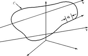
Circulation is defined as the negative of the line integral (defined in mathematics in the counterclockwise sense) of the tangential component of the velocity vector around an arbitrary but fixed closed path in the velocity field, as illustrated in Fig. 4.4. By definition, then:

circulation = Г = – ф V • ds. (4.8)

Thus, a negative sign is introduced into the definition of circulation in Eq. 4.8 because, although mathematicians associate a positive result with a counterclock­wise integration, it is more convenient in aerodynamics applications to define posi­tive circulation as clockwise, as becomes apparent when applications are discussed later. Some authors omit the minus sign in Eq. 4.8 and assume the line integration to be in the clockwise sense. Thus, it is important to specify the direction of integration before evaluating the circulation for a given problem.

The evaluation of the line integral starts at an arbitrary point on the closed path and “marches” around that path in a counterclockwise direction. With each

Circulation

Figure 4.4. Contour C and directed-line segment ds.


Circulation

incremental step of length ds along the path, the velocity component in the direction of the line segment ds is multiplied by the magnitude of ds and the product noted. The line integral is the sum of all of these products. The integrand in the line integral, Eq. 4.8, may be expanded as:

V. ds = iViidsi cos (angle between).

As reviewed in Chapter 3, the vector-dot product is a component-taking operation. Thus, in the integrand of Eq. 4.8, the component of V in the direction of ds is multi­plied by the magnitude of ds as required by the line-integral definition. Note that ds here is an incremental line segment and not a unit vector. That is, ds = dx i + dy j + dz k.

In Cartesian coordinates:

Г = – Pc (мі + vj + wk) • (dx i+dyj + dz k)

C x (4.9)

or Г = – (pc [udx + vdy + wdz.

The circulation may be linked to the curl of the velocity vector and then to the vorticity in a flow by appealing to Stokes’ Theorem, which relates line integrals and surface integrals. By Stokes’ Theorem, if A is any vector, then:

pcA. ds = jj(Vx A). ndS,

s

where n is a unit vector everywhere perpendicular to S and the surface S is the area bounded by the curve C. Think of a closed wire frame, C, oriented in three-space. The surface S would be a diaphragm with edges along C; it need not be in the plane of C and may be of any arbitrary shape.

Letting A be the velocity vector V, Stokes’ Theorem states that:

Equation 4.10 links vorticity (i. e., particle rotation) to the magnitude of circu­lation. Later, a close link between circulation and airfoil lift is demonstrated. The concepts of vorticity, circulation, and curl apply to two – or three-dimensional, com­pressible or incompressible, viscous or inviscid flows.

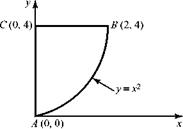
EXAMPLE 4.4 Given: Consider a two-dimensional flow field given by V = (2y) i + (4x) j.

Circulation

Required: Find the circulation around the closed path A-B-C shown here by evaluating the line integral and by using Stokes’ Theorem.

Approach: Because two different methods are required, both the line-integral definition and Stokes’ Theorem are used.

Подпись: A-B: Circulation

Solution: Evaluating the line integral around the given closed path starting at point A:

because along A-B, y = x2 and so (2y)dx = (2×2)dx and (4xdy) = (4y1/2)dy:

C 0 4

B-C: J(udx+vdy) = J(2y)dx + J(4x)(0)dy = – l6, because along B-C, y = 4

B 2 4

A 0 0

and C = A: J (udx+vdy) = J(2y)(0) + J(4x)dy = 0, because along C-A, x = 0.

C 0 4

Circulation

Now, utilizing Stokes’ Theorem:

Appraisal: The two results agree, as they should. Note that this flow is rotational. Also note that here, the curl of the velocity vector for this velocity field is a con­stant independent of x and y, so that the evaluation of the double integral simply amounted to calculating the area of the figure A-B-C. It is important to note that this is a special result; the value of the curl need not always be a constant independent of x and y.

Vorticity and Curl

The rotation or angular velocity, ю, plays a crucial role in the analysis of flow fields in fluid mechanics. In the analysis equations, the rotation term appears so often together with a factor of 2 that this quantity has been given a special name and notation; thus, vorticity = ^ = 2ю. The factor of 2 enters the definition only for con­venience in relating the vorticity to the curl-vector operation.

In Eq. 4.4, multiply both sides by the factor of 2. The resultant expression is 2ю = |. The right side of the equation is identified from vector analysis as a fun­damental vector operation—namely, the curl of a vector. Thus, vorticity = curl V = V x V. From this, it follows that if a flow is irrotational, then the vorticity is zero and the curl of the velocity vector likewise must be zero.

Подпись: C=y+ Zy j + Zz k = Curl V = Подпись: dw dy Vorticity and Curl Подпись: (4.6a)

The expression for vorticity in Cartesian coordinates is:

Подпись: Z = Vx V = Zz k = Подпись: due 1 -JT + - dr r Подпись: du Подпись: k. Подпись: (4.6b)

whereas in plane-polar coordinates, the vorticity vector is given by:

Note that the vorticity vector is normal to the plane of the flow field in a two­dimensional flow.

For a two-dimensional planar field, a flow is irrotational if:

Подпись: (4.7a)dv du dx dy

Vorticity and Curl Подпись: (4.7b)

whereas in planar-polar coordinates, a flow is irrotational if:

If the differential form of the momentum equation, Eq. 3.66, is written for a two­dimensional incompressible flow with all of the viscous terms detailed on the right side, it may be combined with the continuity equation and the definition of vorticity, Eq. 4.6, and written as a single equation for the time rate of change of vorticity of a moving fluid particle, DZjDt. The resulting equation for DZJDt is called the vorticity – transport equation, which shows that DZjDt is proportional to the coefficient of vis­cosity of the fluid. This means that the vorticity or rotation of a particle moving in a fluid changes because of the presence of viscosity. If attention is focused outside of the boundary layer, where the flow may be represented as inviscid (i. e., a flow with zero viscosity coefficient), the time rate of change of vorticity in this flow is zero. Now, the usual viewpoint for aerodynamics problems is to assume that the vehicle is at rest and that the flow is issuing from upstream infinity as a uniform flow. If the flow from upstream infinity is uniform, then none of the fluid particles coming from infinity has any vorticity because all of the velocity-component derivatives are zero. In an inviscid flow, the vorticity continues to be zero, as discussed previously. We conclude that outside of a thin boundary layer, a subsonic flow may be considered irrotational or to have zero vorticity and rotation.