Category Basics of Aero – thermodynamics

Wall Shear Stress at Attachment Lines

The forward stagnation point is a singular point in which the wall shear stress is zero. In three-dimensional flow along an attachment line, like along a separation line, we have a finite wall shear stress, tw > 0. The direction of the wall shear-stress vector tw is coincident with the direction of the attachment line flow, which also holds for a separation line [1]. If we have an infinite swept situation, the wall shear stress is constant along the respective line.

We remember the discussion at the beginning of Sub-Section 7.2.2 and consider the wall shear stress along the attachment line of an infinite swept circular cylinder, ‘scy ’, with the reference-temperature extension in general­ized form [16], assuming perfect-gas flow (This wall shear stress is constant in the z-direction, Fig. 6.37 b).):

Tw, scy scy 1 (7.149)

with

The wall shear stress of the laminar as well as of the turbulent boundary layer increases linearly with increasing dynamic pressure.

The larger T*/Tref, the smaller is the wall shear stress, like in the case of the boundary layer on flat surface portions. For the wall shear stress of the laminar boundary-layer holds tWi lam ж (T*/T^)-0’175 and for that of the turbulent boundary-layer tWi turb ж (T*/T^)-0’653.

For the influence of other factors see the summary for the wall shear stress on flat surface portions at the end of Sub-Section 7.2.3.

[108] In [10] it is shown that the Reynolds analogy is valid strictly only for constant wall temperature. For radiation-cooled surface it hence holds only approximately.

[109] Again we remember that for flat plates at zero angle of attack, and hence also at CAV’s at small angle of attack, except for the blunt nose region, we can choose ‘ref ’ = W, whereas at RV’s we must choose the conditions at the outer edge of the boundary layer: ‘ref ’ = ‘e’.

For both case 1 and case 2, laminar and turbulent flow, we have a linear dependence on the temperature difference Tr — Tw. The larger this differ­ence, the larger is T4a or qgw. However, note that in case 2 Tw is given, whereas in case 1 Tw = Tra is the unknown.

7.2.6 The Thermal State of Stagnation Points and Attachment Lines

Remembering the discussion at the beginning of Sub-Section 7.2.2 we study the situation at a sphere, respectively the circular cylinder (2-D case), and

These are the basic dependencies of the thermal state of the surface. On actual configurations dependencies exist, which are inversely similar to the dependencies of the respective boundary-layer thicknesses, Sub-Section 7.2.1. Important is that super-critical wall roughness, waviness etc. increase either T^a or qgw if the flow is turbulent.

For formulations by other authors of qgw for stagnation points see, e. g., [36].

For laminar and turbulent flow, we have a linear dependence on the tem­perature difference Tr — Tra. The larger this difference, the larger is T4a. Note that in case 2 , which is not included in Table 7.8, Tw is given, whereas in Case 1 Tw = Tra is the unknown.

These are the basic dependencies of the thermal state of the surface. On actual configurations dependencies exist especially for the infinite swept circular cylinder, which are inversely similar to the dependencies of the re­spective boundary-layer thicknesses, Sub-Section 7.2.1. Important is that in the case of the infinite swept circular cylinder super-critical wall roughness, waviness etc. also increase either T4a or qgw if the flow is turbulent.

No exact and reliable non-empirical transition criterion is available today, see Section 8.4.

[116] In [2] it is reported that during a Space Shuttle Orbiter re-entry these are typically at most Me ~ 2.5, and mostly below Me ~ 2.

[117] The (unstable) boundary layer responds to disturbances which are present in flight or, but in general wrongly, in the ground-simulation facility, Sub-Section 8.3.

[118] The thermal state of the surface is seen especially important in view of re­search activities in ground-simulation facilities and in view of hypersonic flight experiments. In both so far the thermal state of the surface usually is either uncontrolled or not recorded.

[119] For a detailed discussion in a recent publication see [15].

[120] The radiation-adiabatic temperature and the heat flux in the gas at the wall with fixed cold wall temperature show a similar qualitative behavior.

[121] Tollmien-Schlichting waves can propagate with the wave vector aligned with the main-flow direction (“normal” wave as a two-dimensional disturbance, wave angle ф = 0) or lying at a finite angle to it (“oblique” wave as three-dimensional disturbance, wave angle ф = 0). The most amplified Tollmien-Schlichting waves in two-dimensional low-speed flows are usually the two-dimensional waves, and in two-dimensional supersonic and hypersonic flows the oblique waves.

[122] In [15] the branches I and II are, less idealized, divided into five stages : 1) dis­turbance reception (branch I ahead of xcr and part of sub-branch IIa), 2) linear growth of (unstable) disturbances (largest part of sub-branch IIa), 3) non-linear saturation (towards the end of sub-branch IIa), 4) secondary instability (towards the very end of sub-branch IIa), 5) breakdown (begin of sub-branch IIb). The term “breakdown” has found entry into the literature. It is a somewhat mislead­ing term in so far as it suggests a sudden change of the (secondary unstable) flow into the turbulent state. Actually it means the “breakdown” of identifiable structures in the disturbance flow. In sub-branch IIb a true “transition” into turbulence occurs. Sub-branch IIb, i. e., the length xtr, u — xtr>l, can be rather large, especially in high-speed flows.

[123] If Ax’tr is large compared to a characteristic body length—a problem in par­ticular appearing in turbo-machinery—, this must be taken into account in the turbulence model of an employed computation method, see, e. g., [20].

[124] This overshoot occurs, because the (viscous sub-layer) thickness of the turbulent boundary layer is initially smaller than what it would have been, if the boundary layer grew turbulent from the plate’s leading edge on.

[125] In reality this is allowed only for large Reynolds numbers, see Sub-Section 7.1.5, page 233. Situations exist in which this assumption is critical, because informa­tion of the mean flow is lost, which is of importance for the stability/instability behavior of the boundary layer (“non-parallel” effects [15]).

[126] Non-local stability theory and methods, see Sub-Section 8.4.1, are based on parabolized stability equations (PSE). With them the stability properties are investigated taking into account the whole boundary-layer domain of interest.

[127] Ovv etc. stands for twofold differentiation with respect to y etc.

[128] The boundary-layer thickness 5, found, for instance, with eq. (7.91), Sub-Section 7.2.1, defines the boundary-layer edge. For practical purposes usually the dis­placement thickness 51 or the momentum thickness 52 is employed.

[129] The reader is warned that this is a highly simplified discussion. The objective is only to arrive at insights into the basic instability behavior, not to present detailed theory.

[130] In this case the result holds only for an air or gas boundary layer, Section 7.1.5, page 231.

[131] Due to the larger amount of tangential momentum flux close to the surface, the turbulent boundary layer can negotiate a larger adverse pressure gradient than the laminar one.

[132] In [33] it is argued that these modes are not necessarily two distinct modes. The authors therefore recommend a new terminology.

Of course, this plot does not indicate how finally the disturbance amplification will behave.

[134] Three transition scenarios can be distinguished [15]: “fundamental breakdown”, i. e., transition due to secondary instability of Tollmien-Schlichting waves, “streak breakdown” due to secondary instability of stream-wise vortices, “oblique break­down”, i. e., transition governed by the growth of oblique waves, which in general happens in two-dimensional supersonic and hypersonic flows.

[135] We remember from Section 6.4.2 that the entropy layer can have a slip-flow profile like shape or a wake-like shape. It appears that so far the wake-like shape has not found much attention.

[136] At a non-swept, infinitely long cylinder an attachment line exists, where the flow comes fully to rest. In the two-dimensional picture this attachment line is just the forward (primary) stagnation point.

[137] This can be a dent on the plate’s surface, or an insect cadaver at the leading edge of the wing.

[138] Remember in this context the global characteristic properties of attached viscous flow, Sub-Chapter 7.1.4.

[139] Regarding the general problems of flow past aerodynamic stabilization, trim and control surfaces see [1].

[140] In Section 1.4 surface catalycity is counted as permissible property. In general this means that it should be as small as possible in order to reduce the thermal loads. One can imagine, however, also to use wall catalycity purposefully in order to influence the boundary-layer behavior via the thermal state of the surface.

[141] In the literature a distinction between critical and effective roughness height can be found. The critical height is the height at which a first impact of the roughness can be determined, usually an upstream shift of the transition location. The effective height is that at which transition is observed directly downstream of the roughness. Yet another increase of the roughness height would not further affect the transition location.

[142] Major issues are the location of the boundary-layer tripping device (roughness elements, etc.) on the wind tunnel model, the effectiveness of the device, and the avoidance of over-tripping (e. g., too large roughness height), which would falsify the properties (displacement thickness, wall shear stress, heat flux) of the ensuing turbulent boundary layer, see, e. g., [83].

[143] The influence on instability (and transition) of the thermo-chemical non­equilibrium of the gas due to freezing phenomena in the nozzles of high-enthalpy simulation facilities, Sub-Section 8.2.7, is also an environment issue, although not a disturbance environment issue.

[144] The apparent dependence of transition on the unit Reynolds number Reu = pu/^ is a facility-induced effect.

[145] For a comparative study of second-mode instability in the Purdue and the Braun­schweig facility see [100].

[146] Note that the result of linear stability theory is the relative growth of (unstable) disturbances of unspecified small magnitude, eq. (8.11) or (8.12), only.

[147] The transition zone in reality is an arbitrarily shaped zone with rather small downstream extent wrapped around the configuration. A low-speed example is discussed in [28].

[148] An alternative approach with a large potential also for optimization purposes, e. g., to influence the instability and transition behavior of the flow by passive or active means, is to use adjoint equation systems [131].

[149] At the (small) blunt nose of such a vehicle of course the edge temperatures are large, but there the boundary layer is not yet turbulent.

[150] We remember that the laminar Prandtl and Schmidt number are in fact functions of the temperature, Section 4.1.

[151] The situation in reality is much more complicated than that at the canonical flat plate/compression ramp configuration: flow through the gap in the hinge line region, surface radiation cooling with non-convex effects, and surface-tangential heat transport in the structure [1].

[152] Depending on the given problem it can be advisable in a computation scheme to take iteratively into account the displacement properties of the boundary layer with, for instance, perturbation coupling, see, Sub-Section 7.2.1.

(C Springer International Publishing Switzerland 2015 E. H. Hirschel, Basics of Aerothermodynamics,

DOI: 10.1007/978-3-319-14373-6 _9

[153] Only in such points streamlines actually terminate at (attach) or leave from (detach or separate) the body surface. This holds also in two dimensions, where the separation point is such a singular point, where the separation streamline leaves the surface under a finite angle [5].

[154] Sub-critical flight means without total-pressure loss due to an embedded shock wave. The schematic holds, however, also for flow with total-pressure loss due to shock waves.

[155] Local separation, however, can have a global influence on the aerodynamic forces and moments of a flight vehicle, if, for instance, the effectiveness of aerodynamic trim or control surfaces is affected.

[156] See also the BDW case study, Section 3.3.

[157] Remember that the lift to drag ratio of the Space Shuttle Orbiter was underes­timated in the supersonic and the subsonic Mach number regime, Section 3.1. How far the insufficient simulation of separation played a role has not yet been determined.

[158] A detailed discussion of the aerothermodynamic issues of stabilization, trim and control devices can be found in [14].

[159] The type V interaction looks similar, but the reattachment shock below the triple point T would have a A like structure, and the expansion fan would originate below T.

[160] We remember from Section 3.1 that the recovery temperature is constant only in the frame of the flat-plate relation given there.

[161] Results of an experimental/numerical study of the length of the separation zone at different wall temperatures are given in Section 10.8.

With increasing angle of attack the excess thermal loads along the leading edge are becoming smaller [24].

[163] For the HERMES configuration it was demanded that the winglets were lying, for all re-entry flight attitudes, completely, i. e., without interference, within the bow-shock surface [40]. For the Space Shuttle Orbiter configuration, but also for a CAV as shown in Fig. 6.4, interactions cannot be avoided and suitable measures must be taken in order to ensure the structural integrity of the airframe.

As we have already noted, it may be necessary to take iteratively into account the displacement properties of the boundary layer, Sub-Section 7.2.1.

Argon is a monatomic gas, the bulk viscosity therefore is zero: к = 0.

[166] Remember that the weak and the strong interaction limits are asymptotic limits with an intermediate area between them, for which however also a description can be provided [47].

[167] However, we have noted above that experience shows that the Navier-Stokes equations can be strained to a certain degree.

This holds also for the experimental realization of the example in the preceding section.

Flow fields of this kind are present at RV’s and AOTV’s at large speeds and altitudes. Hence it is the rule that high-temperature real-gas effects are present in such flow fields.

[170] A major issue is the dependence of the catalytic surface recombination coeffi­cients on the wall temperature, see, e. g., [2].

(C Springer International Publishing Switzerland 2015 E. H. Hirschel, Basics of Aerothermodynamics,

DOI: 10.1007/978-3-319-14373-6 _10

[171] We give the exponent of the relation for the viscous sub-layer and not that for the turbulent scaling thickness, Sub-Section 7.2.1.

[172] Remember that in boundary-layer theory the direction normal to the wall usually is defined as ^-coordinate.

[173] It is to be questioned whether it is permitted to use the boundary-layer ap­proach in this case. Due to the very steep temperature gradient at the wall, the boundary-layer assumptions may not hold.

[174] The viability of the approach to influence the boundary layer by cooling/heating on the middle segment and to investigate the stability properties of the bound­ary layer downstream on the rear segment can be deduced from the theoreti – cal/numerical results given in [7].

[175] Note that the primary separation location is stronger shifted upstream than the attachment location is shifted downstream. This is also observed in laminar ramp flow, Section 10.8.

[176] The enlargement of the boundary-layer thicknesses is shown in the insets in the lower right corners of the figures. (The insets actually show the thicknesses of the temperature boundary layers.) Note that also the separation lengths around the corner point between the two ramps are enlarged. The influence of the wall temperature on both the boundary-layer thickness and the separation length was treated in previous sections.

[177]

q = c^TI-

The value of the constant c is determined at x = 1 m:

c = qx0’5 = 0.0617 MW/m1’5.

[178] We include only the transport of non-equilibrium vibration energy. Equations for other entities, like rotation energy, can be added. For a more general formulation

[179] We have not given the equation(s) for the transport of vibrational energy in Section 5.4, but have referred instead to [5].

[180] Details can be found, for instance, at

http://www. chemie. fu-berlin. de/chemistry/general/si_en. html.

http://physics. nist. gov/cuu/Units/units. html or at

Symbols and Acronyms

Only the important symbols are listed. If a symbol appears only locally or infrequent, it is not included. In general the page number is indicated, where a symbol appears first or is defined. Dimensions are given in terms of the SI basic units: length [L], time [t], mass [M], temperature [T], and amount of substance [mole], Appendix B. The dimensions are written as ‘a/bc’ instead of ‘a/(bc)’ or ‘a b-1 c-1’. For actual dimensions and their conversions see Appendix B.2.

C.1 Latin Letters

A amplitude, p. 287

A surface, [L2]

a speed of sound, p. 153, [L/t]

C Chapman-Rubesin factor, p. 363, [-]

CD drag coefficient, p. 197, [-]

CL lift coefficient, p. 197, [-]

CR resultant (total) force coefficient, p. 198, [-]

c molar density, p. 29, [mole/L3]

c phase velocity, p. 287, [L/t]

Ci molar concentration of species i, p. 29, [mole/L3]

cp pressure coefficient, p. 155, [-]

cp (mass) specific heat at constant pressure, p. 116, [L2/t2T]

cv (mass) specific heat at constant volume, p. 116, [L2/t2T]

D diameter, [L]

D drag, [ML/t2]

DAM 1 first Damkohler number, p. 120, [-]

DAM2 second Damkohler number, p. 120, [-]

Dab mass diffusivity coefficient of a binary system, p. 86, [L2/t]

D’A thermo-diffusion coefficient of species A, p. 103, [M/Lt]

E Eckert number, p. 99, [-]

e internal (mass-specific) energy, p. 96, [L2/t2]

f degree of freedom, p. 115, [-]

f frequency, p. 287, [1/t]

G Gortler parameter, p. 306, [-]

H altitude, p. 2, [L]

H shape factor, p. 247, [-]

h (mass-specific) enthalpy, p. 116, [L2/t2]

ht total enthalpy, p. 38, [L2/t2]

h* reference enthalpy, p. 234, [L2/t2]

j diffusion mass-flux vector of species i, p. 103, [M/L2t]

K hypersonic similarity parameter, p. 209, [-]

K acceleration parameter, p. 306, [-]

Kc equilibrium constant, p. 123, [(L3/mole)v ]

Kn Knudsen number, p. 31, [-]

k thermal conductivity, p. 84, [ML/t3T]

k roughness height, surface parameter, p. 308, [L]

k turbulent energy, p. 313, [L2/t2]

kfr forward reaction rate, p. 123, [L3/molev -1 t]

kbr backward reaction rate, p. 123, [L3/molev -1 t]

kWia catalytic recombination rate, p. 133, [L/t]

L characteristic length, [L]

L lift, [ML/t2]

Le Lewis number, p. 99, [-]

M Mach number, p. 92, [-]

M molecular weight, p. 29, [M/mole]

M moment, [ML2/t2]

MN Mach number normal (locally) to the shock wave, p. 163, [-]

Mi molecular weight of species i, p. 29, [M/mole]

Mо flight Mach number, [-]

M* critical Mach number, p. 154, [-]

Pe Peclet number, p. 98, [-]

Pr Prandtl number, p. 98, [-]

p pressure, p. 29, [M/Lt2]

pe pressure at the boundary-layer edge, p. 199, [M/Lt2]

pi partial pressure of species i, p. 29, [M/Lt2]

q dynamic pressure, p. 154, [M/Lt2]

qо free-stream dynamic pressure, [M/Lt2]

q heat flux, p. 82, [M/t3]

qgw heat flux in the gas at the wall, p. 38, [M/t3]

qw heat flux into the wall, p. 38, [M/t3]

qrad thermal radiation heat flux, p. 44, [M/t3]

q’ disturbance amplitude, p. 287

R gas constant, p. 29, [L2/t2T]

R radius, [L]

R0 universal gas constant, p. 29, [ML2/t2moleT]

Re Reynolds number, p. 92, [-]

Reu unit Reynolds number, p. 26, [1/L]

Red contamination Reynolds number, p. 300, [-]

r recovery factor, p. 39, [-]

volume fraction of species i, p. 30, [-] source term, p. 413, [-]

Schmidt number, p. 104, [-]

species source term, p. 102, 122, [M/L3t]

Strouhal number, p. 81, [-]

Stanton number, p. 38, [-]

entropy, p. 153, [L2/t2T]

temperature, p. 29, [T]

temperature of the gas at the wall, p. 14, [T]

radiation-adiabatic temperature, p. 40, [T]

total temperature, p. 39, [T]

wall temperature, p. 14, [T]

recovery temperature, p. 38, [T]

level of free-stream turbulence, p. 312, [-]

reference temperature, p. 234, [T]

Cartesian velocity components, p. 78, [L/t]

non-dimensional Cartesian velocity components, p. 205, [L/t]

velocity components normal and tangential to an oblique

shock wave, p. 163, [L/t]

free-stream velocity, flight speed, p. 26, [L/t]

viscous sub-layer edge-velocity, p. 243, [L/t]

non-dimensional velocity, p. 243, [-]

friction velocity, p. 243, [L/t]

maximum speed, p. 154, [L/t]

resultant velocities ahead and behind an oblique shock

wave, p. 163, [L/t]

velocities vector, p. 78, [L/t]

interaction parameters, p. 366, [-]

physical velocity components, p. 218, [L/t]

surface suction or blowing velocity, p. 245, [L/t]

Cartesian coordinates, p. 78, [L]

surface-oriented locally monoclinic coordinates, p. 219, [-] mole fraction of species i, p. 29, [-] non-dimensional wall distance, p. 243, [-] real-gas factor, p. 112, [-]


Symbols and Acronyms

u


v


Symbols and Acronyms

C.2 Greek Letters


angle of attack, p. 6, [°]

thermal accommodation coefficient, p. 101, [-] thermal diffusivity, p. 98, [L2/t] wave number, p. 287, [1/L] ratio of specific heats, p. 116, [-]


a

a

a

a

Y


Подпись: Yeff Yia A Ao 6 6 6 6 flow 6M 6T Подпись:Подпись: sc vs 1 Подпись: 62Подпись: Є Є Подпись:Подпись: к X X M M v v Подпись: v- , v- ir ir Подпись:effective ratio of specific heats, p. 178, [-] recombination coefficient of atomic species, p. 132, [-] characteristic boundary-layer thickness, p. 44, [L] shock stand-off distance, p. 176, [L] flow (ordinary) boundary-layer thickness, p. 93, [L] ramp angle, p. 163, [°]

shock stand-off distance (6 = A0), p. 177, [L]

flow (ordinary) boundary-layer thickness (6flow = 6), p. 93, [L]

mass-concentration boundary-layer thickness, p. 104, [L]

thermal boundary-layer thickness, p. 100, [L]

turbulent scaling thickness, p. 243, [L]

viscous sub-layer thickness, p. 242, [L]

boundary-layer displacement thickness (61 = 6і), p. 245, [L]

boundary-layer momentum thickness (62 = в), p. 245, [L]

emissivity coefficient, p. 44, [-]

density ratio, p. 176, [-]

fictitious emissivity coefficient, p. 54, [-]

characteristic dissociation temperature, p. 123, [T]

characteristic rotational temperature, p. 119, [T]

characteristic vibrational temperature, p. 121, [T]

flow angle, p. 78, [°]

shock angle, p. 163, [°]

sonic shock angle, p. 166, [°]

bulk viscosity, p. 90, [M/Lt]

mean free path, p. 31, [L]

wave length, p. 287, [L]

viscosity, p. 83, [M/Lt]

Mach angle, p. 169, [°] kinematic viscosity, p. 227, [L2/t]

Prandtl-Meyer angle, p. 189, [°], [rad]

stoichiometric coefficients, p. 122, [-]

density, p. 29, [M/L3]

partial density of species i, p. 29, [M/L3]

total density, p. 153, [M/L3]

fractional density of species i, p. 30, [M/L3]

surface suction or blowing density, p. 245, [M/L3]

reflection coefficient, p. 94, [-]

relaxation time, p. 121, [t]

thickness ratio, p. 209, [t]

viscous stress tensor, p. 90, [M/t2L]

components of the viscous stress tensor, p. 221, [M/t2L]

skin friction, wall shear stress, p. 256, [M/t2L]

angle, p. 355, [°]

transported entity, p. 79

term in Wilke’s mixing formula, p. 88

p characteristic manifold, p. 227

p sweep angle of leading edge or cylinder, p. 202, [°]

X cross-flow Reynolds number, p. 301, [-]

X, X viscous interaction parameter, p. 364, [-]

Ф’ disturbance stream function, p. 288, [1/t]

ф angle, p. 201, [°]

Q vorticity content vector, p. 218, [L/t]

Qk dimensionless thermal conductivity collision integral, p. 85, [-]

dimensionless viscosity collision integral, p. 83, [-] ш circular frequency, p. 287, [1/t]

ші mass fraction of species i, p. 29, [-]

шк exponent in the power-law equation of thermal

conductivity (шк, шк1, шк2), p. 85, [-] шц exponent in the power-law equation of

viscosity (шм, шмі, шМ2), p. 83, [-]

C.3 Indices

C.3.1 Upper Indices

Подпись: ІПодпись: *i T u + + 4= i = 1, 2, 3, general coordinates and contravariant velocity components

physical velocity component

thermo-diffusion

unit

ionized

dimensionless sub-layer entity reference-temperature/enthalpy value

C.3.2

Lower Indices

A, B

species of binary gas

br

backward reaction

c

compressible

corr

corrected

cr

critical

D

drag

e

boundary-layer edge, external (flow)

elec

electronic

eff

effective

equil

equilibrium

exp

experiment

fp

flat surface portion

fr

forward reaction

gw

gas at the wall

Han

Hansen

i

imaginary part

i, j

species

ic

incompressible

k

thermal conductivity

L

lift

l

leeward side

lam

laminar

M

mass concentration

molec

molecule

ne

non-equilibrium

R

resultant

r

real part

r

reaction

r

recovery

ra

radiation adiabatic

rad

radiation

ref

reference

res

residence

rot

rotational

SL

sea level

Suth

Sutherland

s

shock

s

stagnation point

sc

turbulent scaling

scy

swept cylinder

sp

sphere

T

thermal

t

total

tr, l

transition, lower location

tr, u

transition, upper location

trans

translational

turb

turbulent

vibr

vibrational

vs

viscous sub-layer

w

wall

w

windward side

R

viscosity

T

friction velocity

0

reference

1

ahead of the shock wave

2

behind the shock wave

infinity

critical

C.4 Other Symbols

O() order of magnitude

‘ non-dimensional and stretched

‘ fluctuation entity

v vector

t tensor

C.5 Acronyms

Indicated is the page where the acronym is used for the first time.

Подпись:aeroassisted orbital transfer vehicle, p. 3 ascent and re-entry vehicle, p. 3 blunt delta wing, p. 63 cruise and acceleration vehicle, p. 3 direct numerical solution, p. 296
Future European Space Transportation Investigations

Programme, p. 3

general thermal radiation, p. 54

high alpha inviscid solution (configuration), p. 135

large eddy simulation, p. 313

orbital maneuvering system, p. 52

Reynolds-averaged Navier-Stokes, p. 55

Rankine-Hugoniot-Prandtl-Meyer, p. 19

re-entry vehicle, p. 3

single stage to orbit, p. 3

two stage to orbit, p. 3

thermal protection system, p. 11

[1] A detailed classification of both civil and military hypersonic flight vehicles is given, for instance, in [3].

[2] In [5] non-winged re-entry vehicles (capsules) are considered as a separate vehicle class. Most prominent members of this class are APOLLO and SOYUZ. Capsules flying in the Earth atmosphere at altitudes below approximately 100 km, and with speeds below 8 km/s can be considered as belonging to class 1.

[3] The X-38 was NASA’s demonstrator of the previously planned crew rescue ve­hicle of the International Space Station.

[4] The experimental vehicles X-43A, [8], and X-51A, [9], were dedicated to the tests of scramjet (supersonic combustion ramjet) and ramjet propulsion systems. In the frame of HIFiRE, [10], HIFiRE-2 and HIFiRE-3 were scramjet flight experiments. Boost-glide vehicles go back to the X-20/Dyna-Soar, which has its roots in German studies during World War II [11]. Such vehicles can be counted as CAV’s, however without a propulsion system.

[5] In Section 1.2 characteristic flow features of two particular flight vehicle classes are discussed in some detail.

[6] We note that, for instance, future RV’s may demand large down and cross range capabilities (see some of the FESTIP study concepts [13] and also [5]). Then aerodynamic lift/drag “small” for RV’s in Table 1.1 actually should read “small to medium”.

A free-stream surface is a vehicle’s surface which is not inclined against the free stream.

[8] Sub-critical means that laminar-transition is not triggered prematurely, and that in turbulent flow neither skin friction nor heat transfer are enhanced by surface irregularities, Chapter 8.

[9] The heat flux is the heat transported through a unit area per unit time.

[10] This is the basic definition. A more general definition would include also the temperature gradients in tangential directions. Such situations can be found at vehicle noses, leading edges, inlet cowl lips, etc., see, e. g., [5, 21]. In non­convex situations and if shock layer radiation is present, the definition must be generalized further. For our discussions we can stick with the basic definition.

[11] In this book the direction normal to the wall usually is defined as ^-coordinate.

[12] In the space community the aerodynamic data are sometimes called “data of static longitudinal stability”. This stems from the rocket launch technology. During the launch process the rocket flies longitudinally unstable and must be controlled with aerodynamical or engine-related means.

[13] In [13] it is shown, that with a “locally” defined Knudsen number more precise statements can be made.

[14] It is noted already here, that flow-physics models (laminar-turbulent transition, turbulence, turbulent separation), which are required in viscous flow simulations for altitudes below approximately 50 km, partly have large deficits. This holds also for thermo-chemical models in the whole flight regime considered in this book.

[15] This situation is also called radiation equilibrium.

[16] We neglect here also non-convex effects, Sub-Section 3.2.5, and other possible external heat radiation sources.

[17] The reader may note that we usually omit this word in this book, writing simply “radiation cooling”.

recent publication [7, 8].

[19] Regarding this highly complex phenomenon we cite only an early and a more

[20] Note that on a typical Space Shuttle Orbiter trajectory the maximum thermal loads occur around 70 km altitude [2]. Indeed it has been shown exactly that the maximum heat flux qgw in the stagnation point occurs at approximately 73 km altitude [15].

[21] This leads to the dilemma in the design of CAV’s that on the one hand nose and leading edge radii must be small in order to minimize the wave drag, whereas on the other hand they must be large enough to permit an effective surface radiation cooling. This dilemma does not exist for RV’s. They have on purpose large surface radii and fly at large angle of attack for an effective deceleration. The large radii at the same time also very effectively support surface radiation cooling.

[22] Due to the different characteristic angles of attack, Fig. 1.3, the primary (wing) attachment lines at a CAV (small a) lie indeed at the leading edge (see Figs. 7.8 and 7.9 in Section 7.3), but in contrast to that lie at RV’s (large a) on the windward side (see Fig. 3.16 in Section 3.3, and the upper part of Fig. 9.5 in Section 9.1).

[23] In [18] attachment and separation lines as well as the appearance of extremes of the thermal state of the surface across such lines are treated in detail.

[24] Note that the original emissivity coefficient є is a property only of the vehicle surface material.

More results, in particular regarding the flow in the cavity above the split body flap/elevon of the X-38 are discussed in [2].

[26] In three dimensions the coordinate г and the velocity component w are orthog­onal to the picture plane.

[27] Often also called diffusive transport.

[28] This transport mechanism is not a central topic of this book, see below.

[29] To be precise, viscous flow due to molecular transport refers to “laminar flow”.

[30] In the literature values for the Prandtl number of air at ambient temperatures are given as low as Pr = 0.72, compared to Pr = 0.7368 in Table 4.4. A gas – kinetic theory value of Pr = 0.74 for T = 273.2 K, compared to an observed value of Pr = 0.73, is quoted in [2].

[31] State surfaces for planet atmospheres are available, too. For CO2/N2 atmo­spheres (Mars, Venus) see, e. g., [15].

[32] The governing equations need to be applied in conservative formulation in dis­crete numerical computation methods in order to capture shock-wave and slip surfaces.

[33] Mcrit, iower is the lower critical Mach number, at which first supersonic flow appears at the body surface. For airfoils Mcrit, lower ~ 0.7-0.8. Usually Mcrit, lower is simply called critical Mach number Mcrit.

[34] Mcrit, upper is the upper critical Mach number, at which the flow past the body is fully supersonic except for a subsonic pocket, if the body has a blunt nose. For airfoils Mcrit, upper ~ 1.1-1.2.

[35] Note that in boundary-layer theory the boundary-layer equations are found for Re ^ to, however, only after the “boundary-layer stretching” has been intro­duced, Sub-Section 7.1.3.

[36] This formulation is also employed in Appendix A, where the whole set of gov­erning equations is collected.

[37] The difference Tgw — Tw is called the temperature jump.

[38] Note that in general in all cases the heat fluxes and temperatures are functions of the location at a vehicle surface.

[39] m / Dab 1

— oc ———- OC :

x ux RexSc

The thickness of the mass-concentration boundary layer 5m is related to the thickness of the flow boundary layer 5 = 5fiow by

[40] For a precise definition see Section 6.8.

[41] We recall the discussion in Section 1.2. We noted there that (high-temperature) real-gas effects are strong on the windward side of RV’s and almost absent on their leeward side due to the large angles of attack, at which these vehicles fly. On CAV’s real-gas effects are small to moderate, depending on the flight speed, but are present, to a different degree, on both the windward and the leeward side due to the low angles of attack.

(C Springer International Publishing Switzerland 2015 E. H. Hirschel, Basics of Aerothermodynamics,

DOI: 10.1007/978-3-319-14373-6 _5

[42] That y is not constant in general is due to the vibrational excitation, see below. The gas is calorically not perfect.

[43] The characteristic temperatures GrotN2, &rotO2, and GrotNO are listed in Appendix B.1.

[44] See Table 4.4.

[45] This is the case of air at low temperatures (T 7 400 K, Sub-Section 4.2.3).

[46] This case can be seen in the frame of the “effective ratio of specific heats” ap­proach [6]. Ysff ~ 1.4 can be used to estimate the influence of high-temperature real-gas effects.

[47] The reader should note that translational non-equilibrium is the cause of molec­ular transport (Chapter 4) of momentum (viscous stress), heat (heat conduction) and mass (mass diffusion), and rotational non-equilibrium that of bulk viscosity, [1].

Note that all boundary-layer thicknesses are effectively finite at a stagnation point, and in particular along attachment lines, Sub-Section 7.2.1 and [13].

[49] Such a temperature distribution supports the tendency of surface catalytic N2 recombination at the front part of the windward side of the vehicle, whereas O2 recombination occurs only at the colder middle and aft part.

[50] Close to the surface the mass-diffusion velocity is the characteristic velocity vref, Section 5.4. This means a large residence time and hence DAM 1 ^ to. Catalytic wall behavior, however, is amplifying gradients, and in turn also near-wall non­equilibrium transport phenomena.

The heterogeneous reaction can be formulated in analogy to the homogeneous reaction, eq. (5.30), which we do not elaborate further here.

[52] For a recent explanation of the pitching-moment anomaly see [6]. There it is shown that Mach-number independence in the presence of high-temperature real – gas effects appears only to be given, if the (inviscid) wall Mach number is lower than about Mw ~ 2.2.

[53] If the flow behind the shock wave is a subsonic flow, the shock wave is called strong shock wave. If the flow is supersonic, the shock wave is called weak shock wave.

[54] At hypersonic speeds sharp-nosed cones would suffer untenable large thermal loads, so that cases b) and c) are hypothetical at such speeds.

[55] This is important also with regard to the proper choice of reference data in simi­larity parameters, Section 4.4. Over the CAV the boundary-layer edge Mach and unit Reynolds numbers for instance have approximately the order of magnitude of the free-stream values, Section 1.2. At the RV in particular the boundary-layer edge Mach number Me is much lower: at an angle of attack of a ~ 40° at flight Mach numbers 25 T MT 10 we have a large portion of subsonic flow, and then at most Me ~ 3.

[56] Such a strong-interaction situation is treated in some detail in Sub-Section 9.2.1, third example.

[57] This is to be distinguished from stream-tube flow, where in a tube with varying cross-section uniform distributions of the flow properties are assumed, see, e. g.,

[58] The general formulation in terms of the enthalpy h is h + )u2 = ht, where ht is the total enthalpy of the flow, see also Section 3.1.

[59] We use in this chapter for the convenience of the reader the notation from [11]. There a broad collection of important and useful relations and data concerning perfect-gas compressible air flow is given.

[60] The location of the critical speed of sound is within the viscous shock layer, Fig. 5.4 a). If we consider the shock wave as a discontinuity, a* is a fictitious entity, which is hidden in the discontinuity.

[61] K. Oswatitsch defines hypersonic flow past a body as flow with a free-stream Mach number M^ to. We come back to this in Section 6.8.

This holds for plane flow. At a cone, Fig. 6.14 b), the situation is different.

[63] At a general three-dimensional shock surface, locally the angle between the shock-surface normal and the free-stream direction is 90° – 0. We then define two tangential velocity components at the shock surface.

The effective body shape is the shape, which the free-stream flow “sees”, i. e., the configuration of the flight vehicle at angle of attack, yaw, etc.

[65] Shock waves belong to the same family, if their shock angles в have the same sign. This sign is the same as that of the angles (Mach angles p) of the respective Mach lines (characteristics) of the flow in which they are imbedded [4, 6]. The shock waves belong to opposite families, if their shock angles have opposite signs.

[66] Actually the body contour and these phenomena together with the free-stream properties determine the shape of the bow-shock surface.

[67] We have introduced both the normal and the oblique shock as phenomenological models. They are not curved, and hence we find constant entropy behind them from streamline to streamline.

[68] For the influence of the Mangler effect and the surface temperature on the boundary-layer thickness see Sub-Section 7.2.1.

[69] For the problem of defining this thickness see also Sub-Section 7.2.1.

[70] Actually it is the displacement thickness of the boundary layer which is a stream­line [7]. In three dimensions it is a stream surface.

[71] Indeed, it is only in first-order boundary-layer theory, where the boundary layer is assumed to be infinitely thin, that the inviscid streamline at the body surface is considered as the edge streamline of the boundary layer.

[72] We will see below, that the boundary layer first of all must be thick enough that the effect can happen.

[73] We assume isoenergetic inviscid flow, where the total enthalpy is constant in the whole flow field. Hence for a given free-stream Mach number the (static) temperature behind the shock wave is the smaller the smaller the shock angle в is, eq. (6.85).

[74] This very accentuated step behavior is due to the properties of the employed approximate method. Note that the strong interaction phenomena present at the ramp junctions—Sub-Section 9.2.1—are not captured by that method. The result hence reflects on each ramp the so called asymptotic behavior of the flow [2].

This side in Newton flow is the “hypersonic shadow” side of the flat plate.

[76] For the circular cylinder к = /2 is given in [42] as a more adequate value.

[77] The normal-shock values are included with в = 90°.

[78] We call it Oswatitsch’s independence principle because he was the one who has given the observations and hence the Mach-number independence principle a sound mathematical foundation.

[79] That Mach number independence for the sphere is reached at lower Mach num­bers than those for the cone-cylinder is due to the fact that the bow-shock surface of the former has a larger portion with large shock angle в.

This is permitted, because a constant term is subtracted from the argument of grad s in eq. (6.176).

This result is analogous to that which we obtain for incompressible flow by means of the Laplace equation.

[82] It practice it depends on the design margins where M^ can be placed.

[83] Tsien neglects in this work the occurrence of shock waves and hence obtains results of restricted validity [44].

[84] We remember that three kinds of boundary layers can be present simultaneously: flow, thermal, and mass-concentration boundary layers, Section 4.3.

[85] We remember that the boundary-layer edge is not a streamline, Sub-Section 6.4.2, or here, a stream surface, nearly parallel to the body surface. Only in first-order boundary-layer theory, where the boundary layer is assumed to be infinitely thin, can the inviscid flow at the body surface considered to be the edge flow of the boundary layer. Here it would be the local projections of the loci, where the streamlines cross the boundary-layer edge.

[86] The reader will have noted that we have figures in the text with other notations. We always point this out, because no general nomenclature has been adopted so far in the literature. General surface-oriented “locally monoclinic” coordinates, which make use of the notation of shell theory, denote the tangential coordinates with x1 and x2, whereas the coordinate normal to the body surface is x3 [1]. Accordingly we have the physical velocity components v*1, v*2 and v*3.

[87] The Chapman-Rubesin criterion in any form is of importance only for boundary – layer methods, viscous shock-layer methods, and for thin-layer formulations of the Navier-Stokes/RANS equations. In the full Navier-Stokes or RANS equations the terms in question are present anyway.

[88] Note that locally the boundary-layer edge Mach number Me is relevant, see Section 4.4. This means that the above equations can be employed—if necessary in second-order formulation—on both CAV’s and RV’s, the latter having at the large angles of attack only small boundary-layer edge Mach numbers, Section 1.2.

[89] There are other higher-order effects, which we do not mention here, see, e. g., [11].

The surface boundary conditions for general hypersonic flow have been discussed in detail in Section 4.3.

[91] It is the classical interpretation that an adverse pressure gradient leads to a profile u(y) with a point of inflection, but zero and favorable pressure gradient not. With our generalization we see that also other factors can lead to a point of inflection of the profile u(y).

Regarding the exponent ш we have to keep in mind the temperature interval of the considered problem.

11 Since the unstable behavior was initially observed in explicit solution schemes, it was attributed to a singularity at the location in the flow where M(y) = 1. In

[94] it was shown that the singularity is only an apparent one, and then in [18] that the system of equations is of elliptic/parabolic type in the subsonic part of the flow, if the pressure-gradient term in eq. (7.75) is not omitted.

We call the sum of the skin-friction drag and the form drag in summary “viscous drag” [1].

[96] This Reynolds number can also be formulated as Ree, x in terms of the boundary – layer edge flow properties, or fully generalized as Reref, x, if a suitable reference state can be established.

[97] In the case that the inviscid flow is not known, e. g., in Navier-Stokes/RANS

solutions, but also in experiments, the boundary-layer edge can be defined by vanishing boundary-layer vorticity A e [23]. However, if shock/boundary-

layer interaction has to be taken into account, such a criterion needs to be refined.

[98] The 4-th-power law approach is detested by some authors. Of course there are other more accurate relations. However, if qualitative considerations are to be made, it is, together with the reference-temperature extension, the best approach. This holds also for quick estimations of boundary-layer properties. If a high accuracy is needed, discrete numerical methods together with elabo­rate turbulence models, Section 8.5, anyway are to be employed. Modern hybrid RANS-LES approaches even permit to describe massively separated flow. The biggest challenge—if a flight vehicle is transition sensitive—still is the accurate and reliable prediction of the location and the properties of the laminar-turbulent transition zone in a typical hypersonic flow environment, Section 8.1.

[99] In the following we denote thicknesses of compressible boundary layers with V and those of incompressible ones with ‘ic Regarding the choice of the exponent ш in the viscosity law, the temperatures must lie, at least approximately, in the same temperature interval.

[100] In the literature often 4* and в are used instead of and S2.

[101] This is in contrast to two-dimensional boundary layers, where 41 is always posi­tive, except for extremely cold wall cases [1].

[102] Navier-Stokes/RANS solutions do not explicitly exhibit these properties of at­tached and separating viscous flow. They can be found by a post-processing of the computed results with eq. (7.107) to (7.109).

[103] The name momentum thickness is used throughout in literature [21]. Actually it is a measure of the loss of momentum in the boundary layer relative to that of the external inviscid flow, and hence should more aptly be called momentum-loss thickness.

[104] Also here it holds that for flat plates at zero angle of attack, and hence also at CAV’s at small angle of attack, except for the blunt nose region, we can choose ‘ref ’ = W, whereas at RV’s the conditions at the outer edge of the boundary layer are the reference conditions: ‘ref ” = ‘e’.

The larger T*/Tref, the larger are the boundary-layer thicknesses, except for the momentum thicknesses S2,lam and S2,turb. For a given Mref and a given Tref an increasing wall temperature Tw leads to an increase of the laminar boundary-layer thicknesses Slam and S1ilam (ж (T*/Tref)0 825), which is stronger than the increase of the turbulent boundary-layer thick­nesses 5turb and S1iturb (ж (T*/Tref )0 33). Strongest is the increase of the thickness of the viscous sub-layer Svs, ж (T*/Tref )1’485, and that of the turbulent scaling thickness, ж (T*/Tref)132. Concerning the momentum thicknesses, that of the turbulent boundary layer decreases stronger with increasing wall temperature than that of the laminar boundary layer.

These are the basic dependencies of flat-plate boundary-layer thicknesses on flow parameters and wall temperature. On actual configurations other de­pendencies exist, which are mentioned in the following. In general no explicit

We take к here as a representative permissible surface property, like sur­face roughness, waviness, etc., see Section 1.3. It influences boundary-layer properties, if it is not sub-critical, Section 8.1. A roughness к is critical, if its height is larger than a characteristic boundary-layer thickness, for instance the displacement thickness Si (Sub-Section 8.3). It must be re­membered, that boundary layers are thin at the front part of flight ve­hicles, and become thicker in the stream-wise direction. The influence of surface roughness and the like on laminar-turbulent transition, turbulent wall-shear stress and the thermal state of the surface is known, at least empirically [21, 24]. Its influence on S, however, which probably exists, at least in turbulent boundary layers, is not known.

[105] Although it is actually only one boundary layer, which develops over the vehicle’s surface, usually the boundary layers on the lower and the upper side of the configuration are distinguished.

[106] We remember that for flat plates at zero angle of attack, and hence also at CAV’s at small angle of attack, except for the blunt nose region, we can choose ‘ref ’ = W, whereas at RV’s we must choose the conditions at the outer edge of the boundary layer: ‘ref ’ = ‘e’.

The larger T*/Tref, the smaller is the wall shear stress. For a given Mref and a given Tref an increase of the wall temperature Tw leads to a de­crease of the wall shear stress of a turbulent boundary-layer (tWi turb ж (T*/Tref )-0 67), which is stronger than the decrease of the wall shear stress of a laminar boundary-layer (tWi lam ж (T*/Tref )-0175). A drag-sensitive hypersonic of CAV with predominantly turbulent boundary layer therefore should be flown with a surface as hot as possible. (But see the discussion in Section 10.7.)

These are the basic dependencies of the wall shear stress of flat-plate boundary-layers on the flow parameters and the wall temperature. On actual configurations dependencies exist, which are similar to the dependencies of the boundary-layer thickness 6 mentioned in Sub-Section 7.2.1. In general it holds that a larger boundary-layer thickness leads to a smaller wall shear stress. Important is to note, that a super-critical roughness of the surface will increase the wall shear stress of turbulent boundary layers [21, 24]. The laminar boundary layer in such a case might be forced to become turbu­lent (unintentional turbulence tripping). A drag-sensitive CAV must have a surface with sub-critical roughness etc. everywhere.

Dimensions and Conversions

SI basic units and SI derived units are listed of the major flow, transport, and thermal quantities. In the left column name and symbol are given and in the right column the unit (dimension), with the symbol in ^ [ ] used in Appendix C, and in the line below its conversion to the U. S. customary units.

3

Dimensions and Conversions2.75

2.5

2.25 2

1.75

d

1.5

1.25 1

0.75 0.5 0.25 0

0 5 10 15 20 25 30

kT/e

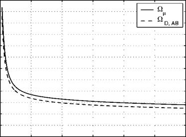
Fig. B.1. Dimensionless collision integrals = Ok, and ODAB of air as functions

of kT/є or kT/єав [4, 6].

SI Basic Units

length, L

[mL ^ [L]

1 m = 100 cm = 3.28084 ft (1,000 m = 1 km)

mass, m

[kg], ^ [M]

1 kg = 2.20462 lbm

time, t

[s] (= [sec]), ^ [t]

temperature, T

[K], ^ [T]

1 K = 1.8 °R

^ TRankine = TFahrenheit + 459.67 TKelvin (5/9) TRankine ^ TKelvin = TCelsius + 273.15

amount of substance, mole

[kg-mol], ^ [mole]

1 kg-mol = 2.20462 lbm-mol

SI Derived Units

area, A

[m2], ^ [L2]

1 m2 = 10.76391 ft2

volume, V

[m3], ^ [L3]

1.0 m3 = 35.31467 ft3

speed, velocity, v, u

[m/sL ^ [L/t]

1.0 m/s = 3.28084 ft/s

force, F

[N] = [kg m/s2], ^ [M L/t2] 1.0 N = 0.224809 lb/

pressure, p

[Pa] = [N/m2], ^ [M/L t2]

1.0 Pa = 10~5 bar = 9.86923-10~6 atm = = 0.020885 lb//ft2

density, p

[kg/m3], ^ [M/L3]

1.0 kg/m3 = 0.062428 lbm/ft3

(dynamic) viscosity, p

[Pa s] = [N s/m2], ^ [M/L t] 1.0 Pa s = 0.020885 lb/ s/ft2

kinematic viscosity, v

[m2/s], ^ [L2/t]

1.0 m2/s = 10.76391 ft2/s

shear stress, т

[Pa] = [N/m2], ^ [M/L t2] 1.0 Pa = 0.020885 lb/ /ft2

energy, enthalpy, work, quantity of heat

[J] = [N m], ^ [M L2/t2]

1.0 J = 9.47813-10-4 BTU =

= 23.73036 lbmft2/s2 = 0.737562 lb//s2

(mass specific) internal energy, [J/kg] = [m2/s2], ^ [L2/t2] enthalpy, e, h 1.0 m2/s2 = 10.76391 ft2/s2

(mass) specific heat, cv, cp specific gas constant, R

[J/kg K] = [m2/s2 K], ^ [L2/t2T] 1.0 m2/s2K = 5.97995 ft2/s2 °R

power, work per unit time

[W] = [J/s] = [N m/s], ^ [M L2/t3] 1.0 W = 9.47813-10-4 BTU/s =

= 23.73036 lbmft2/s3

thermal conductivity, к

[W/m K] = [N/s K], ^ [M L/t3T]

1.0 W/m K = 1.60496-10-4 BTU/s ft °R

= 4.018342 lbm ft/s3 °R

heat flux, q [W/m2] = [J/m2s], ^ [M/t3]

1.0 W/m2 = 0.88055-10-4 BTU/s ft2 = = 2.204623 lbm/s3

(binary) mass diffusivity, Dab [m2/s], ^ [L2/t]

1.0 m2/s = 10.76391 ft2/s

thermo diffusivity, D’A [kg/m s], ^ [M/L t]

1.0 kg/m s = 0.67197 lbm/ft s

diffusion mass flux, j [kg/m2s], ^ [M/L2t]

1.0 kg/m2s = 0.20482 lbm/ft2s

References

1. Taylor, B. N. (ed.): The International System of Units (SI). US Dept. of Com­merce, National Institute of Standards and Technology, NIST Special Publica­tion 330, 2001, US Government Printing Office, Washington, D. C. (2001)

2. Taylor, B. N. (ed.): Guide for the Use of the International System of Units (SI). US Dept. of Commerce, National Institute of Standards and Technology, NIST Special Publication 811, 1995, US Government Printing Office, Washington, D. C. (1995)

3. Hirschfelder, J. O., Curtiss, C. F., Bird, R. B.: Molecular Theory of Gases and Liquids. John Wiley & Sons, New York (1966)

4. Bird, R. B., Stewart, W. E., Lightfoot, E. N.: Transport Phenomena, 2nd edn. John Wiley & Sons, New York (2002)

5. Vincenti, W. G., Kruger, C. H.: Introduction to Physical Gas Dynamics. John Wiley & Sons, New York (1965), Reprint edition, Krieger Publishing Comp., Melbourne, Fl (1975)

6. Neufeld, P. D., Jansen, A. R., Aziz, R. A.: J. Chem. Phys. 57, 1100-1102 (1972)

Constants, Functions, SI Dimensions and Conversions

We provide in Appendix B.1 constants and air properties. In Appendix B.2 the dimensions of the most important quantities are given. The dimensions are in general the SI units (Systeme International d’unites), see [1, 2], where also the constants given in Appendix B.1 can be found. The basic units, the derived units, and conversions[180] to US customary units (English units) are given. Note that we write the dimensions as ‘a/bc’ instead of ‘a/(bc)’ or ‘a b-1 c-1’.

B.1 Constants and Air Properties

The molar universal gas constant R0, the Stephan-Boltzmann constant a, and standard gravitational acceleration g0 are:

Molar universal gas constant R0 = 8.314472-10[181] kgm[182]/s2 kg-molK

= 4.97201-104 lbm ft2/s2 lbm-rnol °R,

Stephan-Boltzmann constant a = 5.670400-10-8 W/m2 K4

= 1.7123-10-9 Btu/hrft2 °R4.

Standard gravitational

acceleration at sea level g0 = 9.80665 m/s2

= 32.174 ft/s2.

In Table B.1 we list some properties of air and its major constituents. The properties were addressed in Chapters 2 and 4. Listed are the molecular weights, the gas constants, and intermolecular force parameters, all for the temperature domain of our interest.

Fig. B.1 shows the dimensionless collision integrals = Qk, and QDab of air as functions of the dimensionless temperatures kT/e or кТ/єАв. The Lennard-Jones parameters e/k [K] for air and its constituents are given in Table B.1.

Table B.2 lists the characteristic rotational, vibrational, and dissociation temperatures of the molecular air constituents N2, O2, and NO.

Table B.1. Molecular weights, gas constants, and intermolecular force parameters of air constituents for the low temperature domain [3, 4]. * is the U. S. standard atmosphere value, + the value from [4].

Gas

Molecular weight M [kg/kg-mol]

Specific gas constant R [m2/(s2K)]

Collision dia­meter a • 1010 [m]

2nd Lennard-Jones parameter e/k [K]

air

28.9644* (28.97+)

287.06

3.617

97.0

n2

28.02

296.73

3.667

99.8

o2

32.00

259.83

3.430

113.0

NO

30.01

277.06

3.470

119.0

N

14.01

593.47

2.940

66.5

О

16.00

519.65

2.330

210.0

Ar

39.948

208.13

3.432

122.4

He

4.003

2077.06

2.576

10.2

Table B.2. Characteristic rotational, vibrational, and dissociation temperatures of air molecules [5].

Gas:

N2

On

NO

Grot [K]

2.9

2.1

2.5

®vibr [K]

3,390

2,270

2,740

Gdiss [K]

113,000

59,500

75,500

Governing Equations for Flow in General Coordinates

Governing Equations for Flow in General Coordinates
We collect the transport equations for a multi-component, multi-temperature non-equilibrium flow.[178] All transport equations have been discussed in Chap­ter 4, as well as in Chapters 5, 6, 7 (see also [2]—[4]). We write the equations in (conservative) flux-vector formulation, which we have used already for the energy equation in Sub-Section 4.3.2, and for three-dimensional Cartesian coordinates:

of mass and of vibration energy.

The conservation vector Q has the form

Q = [Pi, pu, pv, pw, pet, (A.2)

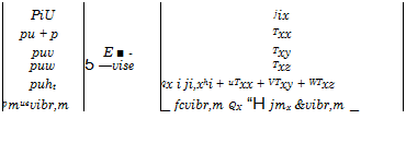
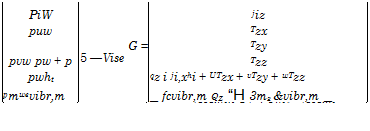
where pi are the partial densities of the involved species i, Section 2.2, p is the density, u, v, w are the Cartesian components of the velocity vector V, et = є + 1/2 V2 is the mass-specific total energy (V = |V|), Sub-Section 4.3.2, and evibT, m the mass-specific vibration energy of the molecular species m. The convective and the viscous fluxes in the three directions read

Подпись: E Подпись: PiU jix pu + p Txx puv E ■ - Txy puw 5 —vise Txz puht qx i ji,xhi + uTxx + VTxy + WTxz pmuevibr,m _ fcvibr,m QX “H jmx &vibr,m _

(A.3)

(A.4)

Подпись: G Governing Equations for Flow in General Coordinates

(A.5)

The convective flux vectors E_, F_, G represent from top to bottom the transport of mass, Sub-Section 4.3.3, momentum, Sub-Section 4.3.1, of total energy, Sub-Section 4.3.2, and of non-equilibrium vibration energy, Section

5.4. [179] In the above ht = et + р/р is the total enthalpy, eq. (5.7).

In the viscous flux vectors Evisc, F_visc, Gvisc, the symbols jix etc. rep­resent the Cartesian components of the diffusion mass-flux vector j. of the species i, Section 4.3.3, and Txx, Txy etc. the components of the viscous stress tensor r, eqs. (7.10) to (7.15) in Section 7.1.3. In the fifth line each we have the components of the energy-flux vector q, eq. (4.58), Sub-Section 4.3.2, which we have summarized as generalized molecular heat-flux vector in eqs. (4.61) and (4.62), the latter being the equation for the heat flux in the gas at the wall in the presence of slip flow. In the sixth line, finally, we find the terms of molecular transport of the non-equilibrium vibration energy in analogy to the terms of eq. (4.59).

Подпись: qx Чу qz Governing Equations for Flow in General Coordinates Подпись: (A.6)

The components of the molecular heat flux vector q in the viscous flux vectors in eqs. (A.3) to (A.4) read, due to the use of a multi-temperature model with m vibration temperatures

The source term S_ finally contains the mass sources Бпц of the species i due to dissociation and recombination, eq. (4.84) in Sub-Section 4.3.3, and the energy sources Qk, m

Qk, m represent the к mechanisms of energy exchange of the m vibration temperatures, for instance between translation and vibration, vibration and vibration, etc., Sub-Section 5.4.

To compute the flow past configurations with general geometries, the above equations are transformed from the physical space x, y, z into the computation space Z, n, C:

Z = Z(x, y,z),

n = n(x, y,z), (A.8)

C = C (x, y,z)-

This transformation, which goes back to H. Viviand [6] and to M. Vinokur [7], regards only the geometry, and not the velocity components. This is in contrast to the approach for the general boundary-layer equations, Sub­Section 7.1.3, where both are transformed. Z usually defines the main-stream direction, n the lateral direction, and C the wall-normal direction, however in general not in the sense of locally monoclinic coordinates, Sub-Section 7.1.3. The transformation results in

dQ дЩ + Ш-visc) _|_ + Eyjsc) 9(G + Gvisc) = g (A 9)

dt dZ di] dQ ~’

which is the same as the original formulation, eq. (A.1).

The transformed conservation vector, the convective flux vectors, and the source term are now

U = J~lU,

E=J-%,E+ZyF + Z, Gl F = J-l[ilxE + ilvF + ilzG], (A.10)

G = J-1[C, E + CyF + CM,

S = J-ls,

with Jbeing the Jacobi determinant of the transformation. The trans­formed viscous flux vectors have the same form as the transformed convective flux vectors.

The fluxes, eqs. (A.3) to (A.5), are transformed analogously, however we do not give the details, and refer instead to, for instance, [8, 9].

Problems of Chapter 10

Problem 10.1

Problems of Chapter 10

In the frame of the reference-temperature concept the Reynolds number is defined as

which can be written as

p ______ poo ^OO % P poo _______ p P poo

р<ж р<ж p р<ж p

Because p = const. across the boundary layer and p ж Tw, we can for­mulate

P^Roo = (ТоА1+Ш Poo At* T* ) ‘

Problems of Chapter 10 Подпись: 0.825

For the thickness of the Blasius boundary layer this leads to

Problems of Chapter 10
For the thickness of the ^-th-power turbulent boundary layer we obtain

Problem 10.2

Problems of Chapter 10

We write

We find the reference temperatures to be T*00K = 631.5 K, and T*400K =

1031.5 K. This gives 5600K/$1,400K « 0.66, which is in good agreement with the measured value « 0.64.

Problem 10.4

The skin friction т of the boundary layer and the skin-friction coefficient cf have the same the reference-temperature proportionality. For turbulent boundary layers it reads

Подпись:-0.67

cf, turb ^

With that we obtain

Подпись: 0.67

Подпись:Подпись: 500KCf, turb, ZOOK cf, turb, 1,600K T, 600K

The free-stream static temperature is TA = 242.22 K. We find the recovery temperature to be Tr = 690.66 K (Pr = 0.74). Because boundary-layer edge data are not available, Te is chosen to be TTO.

With that we find T5*00K = 469.77 K, and T* 600K = 1,019.77 K. This gives cf, turb,500K/cf, turb, 1,600K « 1.68, which is in fair agreement with the measured ratio « 1.66 to 1.4.

A check with Te = 2 T^ yields « 1.6, which shows a relative insensitivity. The result shows that the thermal surface effect on the skin-friction can be explained with the help of the reference-temperature concept. On the other hand the effect can be estimated with that concept, which can be helpful in design work.

Reference

1. Hirschel, E. H., Weiland, C.: Selected Aerothermodynamic Design Problems of Hypersonic Flight Vehicles. Progress in Astronautics and Aeronautics, AIAA, Reston, vol. 229. Springer, Heidelberg (2009)

Problems of Chapter 9

Problem 9.1

With the relations given in Chapter 6 we find cPs = a) 1.827, b) 1.839. The closeness of the values reflects the Mach-number independence principle.

Problem 9.2

ps = a) 47.3-рж, b) 84-рж, c) 129.7-рж d) ж-рж. The pressure ps increases with increasing Mach number. It is only the pressure coefficient, which be­comes Mach-number independent. The excess pressure in the Edney type IV case is Aps = 706-рж.

Problem 9.3

We measure in Fig. 9.21 the shock angle to в « 11.8°. This gives M^N « 2.58. This is somewhat above the permissible value given in Sub-Section 6.3.3.

The flat-plate results nevertheless are acceptable, because Figs. 9.23 and 9.24 show that the Rankine-Hugoniot values are met quite well.

Problem 9.4

X = 20.77, V = 0.1296. If a hot wall is assumed, we get хсгц = 180.09 cm, with the cold wall assumption xcrit = 17.05 cm. With the total temperature being To ~ 3,500 K, the wall can be considered as cold wall. The dimensionless critical value then is xcrit (= x/Lsfr) = 2.55. Fig. 9.23 shows that for x = 2.5 the static pressure has almost attained the plateau typical for boundary-layer flow.

Problem 9.5

At x = 1 m we find x = 0.185, V = 0.004. The critical value is хсгц = 0.002 m. Strong interaction phenomena could be neglected if the lower stage of SANGER would have a sharp nose.

Problem 9.6

At x = 1 m we find x = 1-662 and V = 0.0166. хсгц = 0.173 nr. In the nose region strong interaction phenomena are to be expected.

Problems of Chapter 7

Problem 7.1

Solution: a) 6 = 0.005 m, = 0.00172 m, S2 = 0.00066 m, Hn = 2.591.

b) 6 = 0.0233 m, 61 = 0.00292 m, 62 = 0.00227 m, H12 = 1.286, 6vs = 0.000116 m, 6sc = 0.000535 m.

Problem 7.2

Solution: a) 6 = 0.0158 m, 61 = 0.00544 m, 62 = 0.00209 m, H12 = 2.591.

b) 6 = 0.147 m, 61 = 0.0184 m, 62 = 0.0143 m, H12 = 1.286, 6vs = 0.000146 m, 6sc = 0.000848 m.

Problem 7.3

Table 7.3 gives besides others the dependence of the thicknesses on the run­ning length x. The numerical results show that indeed in the turbulent cases a stronger increase is given than in the laminar cases. The thickness of the viscous sub-layer, respectively the scaling thickness, grows only very weakly. These thicknesses govern the skin friction and the heat flux in the gas at the wall in turbulent boundary layers.

Problem 7.4

Problems of Chapter 7

Integrate the general expression for the skin friction, eq. (7.146), along the flat plate and find with Reref = pref vref Lref /^ref, and the exponent of the power-law relation for the viscosity, eq. (4.15), u^2 = 0.65 the skin-friction drag with reference-temperature extension of the flat plate wetted on one side

Problems of Chapter 7 Подпись: 2Df,c,lam = 2 1 f T* Q>x> Arej (h>.cre^yJ)l“1'^ Trej Подпись: 0.175

The skin-friction drag coefficients for the flat plate in compressible flow— wetted on both sides—are the familiar ones, but now with reference – temperature extension (note that Aref = bL):

Problems of Chapter 7 Подпись: f ,c,turb Яж Aref Подпись: 1 / T* (Reref,L)0'2 Tref Подпись: 0.67

and

Remember that eq. (7.146), and hence also these equations, hold only in a certain Reynolds number range. See in this regard the discussion in the summary of Sub-Section 7.2.1.

Problem 7.5

Re^,L = 1.691 108, Яж = 30,165.63 Pa. a) Df, c,lam = 8,963 N, b) Df, c,lam = 8,308 N.

Problem 7.6

Df, turb = a) 72480 N, b) 54,437 N.

Problem 7.7

The turbulent skin-friction drag is much higher than the laminar one. The ratio ‘turbulent drag’ to ‘laminar drag’ is a) 8.1 and b) 6.5.

A higher wall temperature reduces the skin-friction drag, much more for turbulent than for laminar flow. For laminar flow the drag is reduced by 7.3 per cent for the higher wall temperature, for turbulent flow by 25 per cent.

Problem 7.8

We take as reference temperatures the boundary-layer edge temperatures each. The dynamic pressure, the skin-friction coefficient, and the skin-friction drag at the windward side are qe, w = 51,433 Pa, CD, f,w = 8.022-10-4 and Df, w = 76,742 N, and at the leeward side qe, l = 15,692 Pa, CD, f,l = 7.343-10~4 and Df, l = 21,699 N. The total skin-friction force is Df, t = 98,441 N.

The lift component is Lf = —sin a Df, t = —10,290 N and the drag com­ponent Df = cos a Df, t = 97,902 N.

Problem 7.9

We add the inviscid and the skin-friction parts and find L = 1,21 -106 N and D = 0.226-106 N. Compared to the purely inviscid case the lift-to-drag ratio is reduced to L/D = 5.35. This is a realistic order of magnitude for a CV at

Mж = 6, see, e. g., [1].

The viscous forces are of large importance for CAV’s. This is in contrast to RV’s, where the viscous drag is only a small part of the total drag. Note that for this problem only the skin-friction drag was taken into account, not also the form drag. This is allowed, because of the large wetted surface of the CAV.

Problems of Chapter 6

Problem 6.1

The relation for the maximum speed is eq. (6.15), which yields with cp = 1004.71 m2/s2K for air as perfect gas the maximum speed Vm = 1,736,12 m/s.

Problem 6.2

The critical speed is found from eq. (6.19) and is u* = 708.77 m/s. Problem 6.3

The pressure coefficient is found with eq. (6.37): cp = a) indeterminate solu­tion, b) 1.000025, c) 1.0025, d) 1.064, e) 1.276.

The result a) points to the fact that eq. (6.37) is not valid for incompress­ible flow, remember Problem 4.5. For incompressible flow eq. (6.38) with u = 0 at the stagnation point yields the correct value cp = 1.

Problem 6.4

The pressure coefficient is found with eq. (6.65): cp = a) 1.276, b) 1.809, c) 1.832, d) 1.839.

Problem 6.5

Подпись: (Ao =)RS - Rb = eRs : Rs Подпись: Rb 1-е Problems of Chapter 6

Eq. (6.120) in the simplified form must be formulated in terms of the body radius Rb:

The shock stand-off distances are A0 = a) 0.25 m, b) 0.21 m, c) 0.2 m. With increasing Mach number the stand-off distance becomes smaller.

Problem 6.6

A0 = a) 0.146 m, b) 0.11 m, c) 0.1 m. With decreasing Yeff the stand-off distance becomes smaller.

Problem 6.7

A0 = a) 0.042 m, b) 0.01 m, c) 0 m. With Yeff = 1, the stand-off distance becomes even smaller. For Ыж ^ ж the stand-off distance becomes zero.

Problem 6.8

At H = 30 km altitude the relevant free-stream parameters are Тж = 226.509 K and рж = 1.841-10-2 kg/m3. The dynamic pressure is qж = 30,165.62 Pa. The resultant forces and the moment are L = 1.22-106 N, D = 0.128-106 N, M = 48.8-106 Nm. The lift-to-drag ratio is L/D = 9.51.

Problem 6.9

At H = 40 km altitude the relevant free-stream parameters are Tж = 250.35 K and рж = 3.996-10~3 kg/m3. The dynamic pressure is qж = 7,236.54 Pa. The resultant forces and the moment are L = 0.292-106 N, D = 0.031-106 N, M = 11.7-106 Nm. The lift-to-drag ratio is L/D = 9.51.

Problem 6.10

At the higher altitude the density рж is smaller. Hence the forces are smaller. Increasing the angle of attack would enlarge the lift, but also the drag. In­creasing the wing area would increase the wing’s mass. This would make necessary a larger lift.

During a cruise flight the fuel mass decreases with flight time. If the angle of attack is kept constant this would mean an increase of the flight altitude with time. The flight altitude hence is not constant.

Problem 6.11

At higher altitudes we have в = 1.40845-10~4 1/m. The density at sea level is PH=0km = 1.225 kg/m3.

For Mж = 6 at T* = 242.55 K we find vж = 1873.28.8 m/s. With q= 60 kPa this gives рж = 0.0342 kg/m3. The altitude is found from the inverted eq. (2.3) to be

H=-~ InjW – « 25 km. в PH=0km

Problems of Chapter 5

Problem 5.1

The ratio of specific heats reads

Подпись:Подпись: f/ + 2

/

From this we obtain 2

Y – 1 and

/ I -/ —r 1 . I -/ r 1 t QO*

Y-1

Problem 5.2

a) From Section 6.2 we obtain the relation for the maximum speed

tm = V – І’I-

which yields Vm = 6324.5 m/s. Because the static temperature T is zero, the speed of sound is zero and the Mach number is infinitely large.

b) The specific heat at constant pressure of the Lighthill gas is cPL =4 R = 1148.24 m2/s2 K.

The relation for the exit speed is

vexit 2(ht CPL Texit)?

which yields vexit = 6140.3 m/s.

For the Lighthill gas the ratio of the specific heats is yl = 1.333. The speed of sound aexu = a/yl RTexu = 608.9 m/s and the Mach number Мєхц = 10.08.

c) The relation for the exit speed with 20 per cent of the reservoir enthalpy frozen is

Vexit — J 2(0.8 ht c. pL Texit),

which yields vexit = 5656.8 m/s. With the same speed of sound assumed as for c), the exit Mach number is Mexit = 9.29.

d) The general result is that both the nozzle exit speed and Mach number are affected by the different thermodynamic conditions. Read again Sub-Section 5.5.2.

Problem 5.3

Подпись: cp Problems of Chapter 5

The static temperature at H = 30 km altitude is = 226.509 K. The specific heat at constant pressure is

In terms of у this reads

cP = -^-R.

Y – 1

a) The ratio of specific heats at Tx = 226.509 K is y = 1.4. The specific heat at constant pressure then is cp = 1004.71 m2/s2K.

With that we obtain

ht = CpT + [177]— = 2, 227, 575.86 nr/s2.

From this the total temperature is found to be Tt = ht/cp = 2,217.1 K.

b) With y =1.3 the specific heat at constant pressure is cp = 1243.92 m2/s2K. The total temperature then is Tt = ht/cp = 1,790.76 K.

c) With y = 1.1 the specific heat at constant pressure is cp = 3157.66 m2/s2K. The total temperature then is Tt = ht/cp = 705.45 K.

d) The value y =1.3 appears to lie in a realistic range, see Fig. 5.2.

Problem 5.4

We measure the heat flux at the two locations and find q = 0.0617 MW/m2 at x = 1 m and q = 0.0247 MW/m2 at x = 6 m.

Eq. (3.27) reduces in our case to

At x = 6 m we then obtain the scaled value q = 0.0617/605 = 0.0252 MW/m2.

The difference to the measured value is Aq = + 0.0005 MW/m2, which is about 2 per cent difference. With regard to the distance x, eq. (3.27) scales the computed heat flux quite well.