Category Canonical impulse solutions

Transonic airfoils Airfoil performance characterization

For a compressible airfoil flow, both Cd and a depend on the three parameters a, , ReTO. But when examining airfoil performance it’s more useful to combine these into the form,

Cd(ce, M^,Be

CO )

Transonic airfoils Airfoil performance characterization

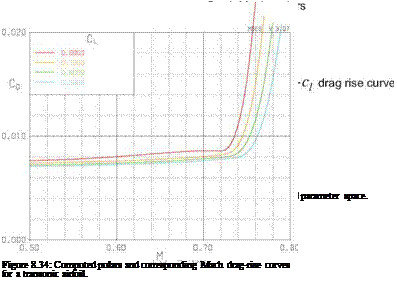
in which a is a dummy parameter. We can now consider individual drag polars at fixed, or alternatively individual Mach drag-rise curves at fixed q. These two types of slices through the |cd, c^,M00j airfoil parameter space are sketched in Figure 8.33. To allow application to a swept wing, the Cd is actually broken down into separate friction and pressure drag components Cdf and Cdp, with the split either estimated or computed directly. Actual computed curves are shown in Figure 8.34.

Strictly speaking all these drag coefficients also depend on ReTO, but with the fully-turbulent flows found on large jet aircraft the drag coefficient scales roughly as Cd ~ log(RsTO)-2, which is a quite weak dependence.

Airfoil performance drivers

Подпись: Wfuel = WZ Подпись: / CD TSFC R . 1 ехр(м^ам^^7 " Подпись: (8.175)

The fuel weight required by an aircraft to fly a specified range R is given by the Breguet relation,

where WZF is the zero-fuel (landing) weight, and TSFC is the engine thrust-specific fuel consumption. The particular grouping TSFC/M^2 is chosen because for modern turbofan engines this ratio is nearly independent of MTO (i. e. TSFC varies as МЦ2), so that the remaining factor CD/МЦ2Сь isolates and measures the aircraft’s aerodynamic performance for fuel economy. It is therefore of great interest to find the best airfoil, Cl, Mto, and wing-sweep combination which minimizes this parameter.

TSD equation analysis

The simplest description of transonic flow is provided by the TSD equation (8.59) derived earlier, which can be re-written in the following form.

S фхх + фуу + фХХ — 0 (8.170)

S(r) = 1 – Ml – (y+1)Ml фх ~ 1 – M2 (8.171)

Superficially, the TSD equation has the same form as the PG equation, except the global coefficient 1—Ml is replaced by the local coefficient S(r). This is approximately the local 1 — M2 value, to first order in

the perturbation x velocity фх. The assumption Ml ~ 1 was also made to slightly further simplify the y+1

factor in the higher-order фх term. This S is in effect a “sonic discriminator,” since S > 0 in subsonic regions which have a Laplace-like behavior, and S < 0 in supersonic regions which have a wave-like behavior. The TSD equation in the transonic regime is therefore a PDE of mixed type. The sonic line (or sonic surface in 3D) which forms the boundary of the supersonic zone is the M — 1 or S — 0 isocontour.

It’s useful to see how the nonlinearity of the TSD equation is capable of representing shock waves. To examine this we consider the 2D TSD equation written in divergence form,

Подпись: (8.172)(1-Ml )фх

TSD equation analysis

and integrate this over a small distance xo…x, as shown in Figure 8.32.

TSD equation analysis Подпись: (1-Ml )фх TSD equation analysis Подпись: 0 B — Ax Подпись: (8.173)

We will assume that фгг ~ A is constant, which corresponds to the streamlines being convergent (A < 0) or divergent (A > 0).

Подпись: Cp(x) where C (х) Подпись: c; ± J{c;)2 + c 8 В — Ax Y+1 Mf Подпись: (8.174)

The integration constant B will depend on A and also on the value of фх at the initial point x0. The above relation (8.173) is a quadratic equation for the perturbation speed фх, or equivalently Cp — -2фх, which has the following solution.

This admits two distinct solutions, C+ > C* (subsonic) and Cp < C* (supersonic), which can be inter­preted as the flows on the two sides of a normal shock This simplified analysis does not predict where the shock will occur, which in an actual TSD solution would be implicitly determined by the freestream Mach number and the overall airfoil geometry

Transonic Flows

8.9.1 Onset of transonic flow

Any aerodynamic body has a maximum local velocity and local Mach number value somewhere near the surface which is greater than the freestream. Hence, as the freestream Mach number over a particular geometry at some angle of attack is gradually increased from small values, the maximum local Mach number max(M) will eventually reach and then exceed unity while the freestream is still subsonic, or < 1. The freestream Mach value when the threshold max(M) = 1 is crossed is called the critical Mach number
for that particular geometry and angle of attack. For potential flow over the body, the local Mach number field has the functional form M(r; MTO), so that the defining condition for the critical Mach can be stated as

max [ M(r; Mcrit) ] = 1

r

Cp*(MTO) = Cp(1; MTO)

Подпись: 2 7Ж Transonic Flows Подпись: 1 Подпись: (8.169)

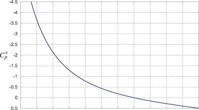
where in practice only the surface points r need to be examined for the maximum local Mach number. An equivalent criterion is in terms of the sonic pressure coefficient, shown in Figure 8.29, which is defined from the Cp(M; MTO) function (8.11) with M = 1 substituted.

An alternative definition for the critical Mach number is then defined as follows.

min [ Cp(r ; Merit) ] = Cp*(MTO)

Transonic Flows

0.3 0.4 0.5 0.6 0.7 0.3 0.9 1 1.1 1.2 1.3 1.4

Figure 8.29: Critical pressure coefficient vs. freestream Mach, for air (7 = 1.4).

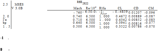
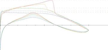
At the typical flight Mach numbers MTO ~ 0.7… 0.85 of jet transport aircraft, only modestly negative local Cp values of -0.75 …—0.3 are required to reach a local M = 1. Consequently, such aircraft necessarily have transonic flow over their wings. Figure 8.30 shows computed Cp(x) distributions for a typical “supercritical” airfoil designed to operate in the transonic condition, which occurs for MTO > Mcrit = 0.71 for this airfoil at this angle of attack. Larger angles of attack make the upper-surface Cp values more negative, and hence decrease Mcrit. In general, each airfoil will therefore have some Mcrit(a) or Mcr-lt(ct) dependency, depending on whether a or q is being held fixed as MTO is varied.

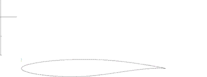
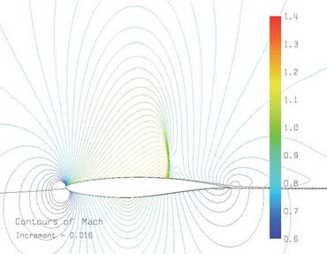
The supersonic region over the airfoil which appears in transonic flow is typically terminated by a normal shock wave, as described in Section 8.3 earlier in this chapter. The shock for the RAE 2822 airfoil for the MTO = 0.76 case is shown in Figure 8.31, along with the Mach waves or characteristics (see Section 8.8.2). These characteristic lines are defined by (8.133), except that the characteristic slope в is defined using the local supersonic M values ahead of the shock rather than MTO.

As MTO is increased beyond Mcrit, the shock wave strengthens and causes a very rapid increase in the overall profile drag. This is due to the increase in the shock’s own wave drag (see Section 8.3), and also due to the boundary layer being subjected to the intense adverse pressure gradient of the shock wave which increases the boundary layer’s downstream momentum defect. Consequently, economical transonic operation is fea­sible at a freestream Mach which is only slightly beyond Mcrit. The consequences for swept wing design will be discussed further in Section 8.9.3.

Transonic Flows

Transonic Flows

Figure 8.30: Cp(x) distributions over RAE 2822 airfoil at а = 1°, for a range of freestream Mach numbers MTO. The Cp levels for each are also shown as dotted lines. The critical Mach number

is Mcrit — 0.71, with a shock wave forming for >Mcrit.


Transonic Flows

Figure 8.31: Mach isocontours and Mach waves over RAE 2822 airfoil at а = 1° and = 0.76 .


Transonic FlowsTransonic FlowsTransonic Flows

Supersonic lifting flows Supersonic lift singularities

To represent the flow over lifting surfaces we need supersonic z-doublets which are derived from the source.

1 – f32z 2tt h3 0


x > /3Jy2+z2 x < /3Jy2+z2


Supersonic lifting flows Supersonic lift singularities

(8.159)


Supersonic lifting flows Supersonic lift singularities

The corresponding y-doublet for modeling sideforce can also be considered. But this has exactly the same form as the z-doublet with y and z swapped, so there is no need to derive this separately.

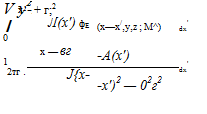
We now define the potential of a semi-infinite z-doublet line extending downstream from the origin, which can be considered as a supersonic horseshoe vortex with an infinitesimal width dy.

Supersonic lifting flows Supersonic lift singularities

4>Tz (x, y,z ; MTO) =


(8.160)


2n y2+z2 h


Supersonic lifting flows Supersonic lift singularities

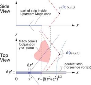
The upper integration limit over the doublet strip is the x’ point where the strip intersects the field point’s upstream Mach cone. This can be determined as the x’ point where the hyperbolic radius from the field point is zero.

h{x-x’,y, z;Moo) = J (X — X1)2 — fi2(y2 + Z2) = 0 —> xf = x — j3Jy2+z2

The alternative positive-root solution x’ = x + /І Jy2 I z2 is not used, since this con’esponds to the down­stream Mach cone, and any doublet in this Mach cone has no influence on the field point.

As an example application of superposition of infinitesimal horseshoe vortices (8.160), the potential of a general unswept lifting line extending from y = — b/2 to y = b/2 is obtained by superposition of this unit solution across the span, with the appropriate y-coordinate shift.

Supersonic lifting flows Supersonic lift singularities

<^(x, y,z ; MTO)


x


Supersonic lifting flows Supersonic lift singularities

(:y-y’)2+z2 sjx2 – j32[{y-y’)2+z2]

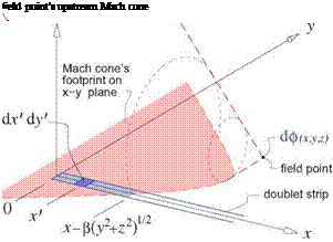
field point’s

^ upstream Mach cone

Supersonic lifting flows Supersonic lift singularities


Supersonic lifting flows Supersonic lift singularities

Figure 8.26: Integration over each doublet strip is restricted to region inside the field point’s up­stream Mach cone.

The y1 and y2 integration limits are obtained by first finding the Mach cone where h(x, y-y’,z; MTO) = 0, which gives У = y± at the Mach cone. These are then clipped to within the lifting-line tips at ±b/2.

Подпись:Подпись: (8.162)У + y/(x/l3)2-z2 у – y/(x/f3)2-Z2 max{—b/2 , min[b/2 , y + ]} max {-b/2 , min[ b/2 , y – ]}

Supersonic lifting flows Supersonic lift singularities Supersonic lifting flows Supersonic lift singularities Подпись: (8.163)

For the specific case of a uniform Г(у) = constant distribution, which corresponds to one horseshoe vortex for the whole wing, the superposition integral (8.161) evaluates to the following form.

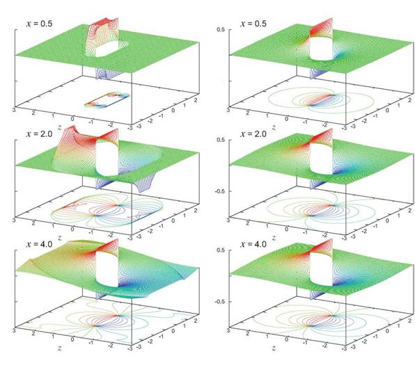
This is shown in Figure 8.27 over yz planes at three downstream x locations, and compared to the subsonic version for = 0.

Two limiting cases are:

Г [8]

2-7Г 121

Г *

2 R

Подпись: Ф(x,y,z; MTO) Подпись: {arctan[+^j — arctan[—^]} Подпись: (8.164)

• Near the lifting line, such that with y± inside the tips (not clipped to ±b/2) and x being close to the z-axis and within the Mach lines from the vortex at the origin, we have the a solution of the 2D airfoil in the limit of zero chord.

This is shown in Figure 8.27 for x = 0.5 on the left.

Supersonic lifting flows Supersonic lift singularitiesУ

Подпись: У

Подпись: 0.5 Supersonic lifting flows Supersonic lift singularities Подпись: (8.165)
Supersonic lifting flows Supersonic lift singularities
Подпись: 3
Supersonic lifting flows Supersonic lift singularities
Подпись: У
Подпись: У Подпись: У
Подпись: 0 Supersonic lifting flows Supersonic lift singularities

Figure 8.27: Potential field over yz planes behind a supersonic (left) and subsonic (right) horseshoe vortex. Away from the Mach cone, the two flows become the same downstream. •

Hence, the Trefftz plane flow here is the same as with an incompressible freestream, as shown in Figure 8.27 for x = 8. For the intermediate downstream distance x = 2, The Trefftz plane flow appears subsonic close to the trailing legs, but supersonic farther away near the Mach cone trace.

Wave drag of a lifting surface

The flow over a general thin supersonic lifting wing can be obtained by superposition of infinitesimal super­sonic horseshoe vortices (8.160) over its surface. The integration limits of such superpositions must obey the Mach cone dependence requirements, which can become complex for general wing planforms. One approach which handles these requirements in a systematic manner is the method of Evvard and Krasil – shchikova, as summarized by Ashley and Landahl [50].

The supersonic wave system created by the horseshoe vortex distribution will in general produce a wave drag due to lift, much like the line source representing a body produced a wave drag due to volume or thickness. Jones [64] determined the following minimum wave drag due to lift, which is obtained by a wing which has elliptical loading both in the spanwise and in the chordwise directions.

°’" = i<8Л66)

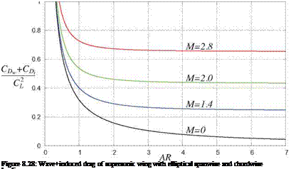
Подпись: Dw + Di Supersonic lifting flows Supersonic lift singularities Supersonic lifting flows Supersonic lift singularities Подпись: (8.167)

Combining this with the classical induced-drag relation (5.71) for the elliptical-loading case gives the total supersonic drag due to lift.

Supersonic lifting flows Supersonic lift singularities Подпись: (8.168)

This can also be given in the usual non-dimensional form using the lift and drag coefficient definitions.

The last term in (8.167) proportional to AR2 favors low aspect ratios so that the lift is distributed over a large chord. This is in direct contrast to the subsonic case, where the chordwise loading distribution is immaterial to drag due to lift. One practical consequence is that efficient supersonic configurations tend to favor relatively low aspect ratios in order to spread out the lift load in the chordwise direction.

Wave drag of arbitrary slender bodies of revolution

The control-volume wave drag analysis of a 2D airfoil, which gave result (8.138), extends readily to the axisymmetric body of revolution. The result is

Dw = – pxVi//фг фх dS (8.152)

Подпись: Dw Подпись: 4-7Г Wave drag of arbitrary slender bodies of revolution Подпись: (8.153)

where the integral area element dS is on a cylindrical “pipe” surface surrounding the body and aligned with the freestream. The potential p can be obtained by the line-source superposition integral (8.145). Ashley and Landahl [50] combine these two expressions and give after some manipulation

where body extends over x = 0… l. Note that the drag depends on the square of dA/dx = d2A/dx2, so that low wave drag dictates bodies which have smooth cross-sectional area distributions. This is one example of Whitcomb’s supersonic area rule, discussed in detail by R. T. Jones [61].

Bodies with minimum wave drag

Following Sears [62] and Haack [63], the line source model developed above will now be applied to a body of length l, with some arbitrary area distribution A(x). Using the trigonometric coordinate d(x)

l l

x = – (1 — cost?) , dx = – sind dd (8.154)

Wave drag of arbitrary slender bodies of revolution Подпись: (8.155)

the line source strength or equivalently dA/dx is expanded in a Fourier sine series.

о 2 о 16

The n = 1 series term has been excluded because it gives a finite base area at x = l. In reality the large separated wake generated by the base area would make the present potential-flow model results not very realistic for that case.

Wave drag of arbitrary slender bodies of revolution Wave drag of arbitrary slender bodies of revolution Wave drag of arbitrary slender bodies of revolution Wave drag of arbitrary slender bodies of revolution

The area distribution A(x) and the total body volume V can then also be given in terms of the same series coefficients.

Substitution of the source strength expansion (8.155) into the wave drag expression (8.153) gives the fol­lowing result, obtained by Sears.

Подпись: DwnBn

Wave drag of arbitrary slender bodies of revolution Подпись: (8.158)

8 n=2

Comparing the volume expression (8.157) with the wave drag expression (8.158) we see that the lowest wave drag for a given body volume V and length l is obtained by setting B3 = B4 … = 0 and leaving only B2 nonzero. The resulting shape is the Sears-Haack body, shown in Figure 8.25. Note that its wave drag is independent of the freestream Mach number, provided of course that is sufficiently far into the supersonic range as required by the assumed supersonic PG flow model.

The very strong dependence of wave drag on the volume and the inverse length is the primary reason why the design of supersonic aircraft naturally favors a long and slender layout with minimal volume. These design drivers are not present in subsonic aerodynamics.

Wave drag of arbitrary slender bodies of revolution

Wave drag of arbitrary slender bodies of revolution

Figure 8.25: Sears-Haack body shape R(x) which gives minimum supersonic wave drag for given length and volume. Corresponding body cross-sectional area A = nR2 is also shown.


. Canonical supersonic flow

The PG transformation (8.65), (8.66) can be applied to the supersonic case if the redefined в is used. Now the PG equation (8.60) reduces to

— фхх + фуу + <f>zz — 0 (8.142)

which is the wave equation. It has an implied M00 = y/2,p = l, so that its characteristics have slopes of ±1. This is called the canonical supersonic flow. This is only a minor simplification from the physical flow, since it does not provide any special advantages for solving supersonic flow problems, unlike in subsonic flow where the canonical flow is incompressible. Here its main advantage is theoretical, in that the properties of all small-disturbance supersonic flows can be investigated by considering only the canonical case.

8.8.3 Supersonic singularities

The linearity of the PG equation allows the construction of general 3D flows by superposition of supersonic singularities. These are analogues of the subsonic source, vortex, and doublet singularities, but have a num­ber of important differences. One major difference is that a supersonic singularity is singular everywhere on its Mach cone surface, not just at a single point like in the subsonic case, and is also undefined in some regions of space. These features will require care in the construction of supersonic superposition integrals.

Hyperbolic radius

For defining supersonic-singularity kernel functions, a useful field function is the hyperbolic radius,

/Hr;Moo) = л/х2 -{Ml-l){y2+z2) (8.143)

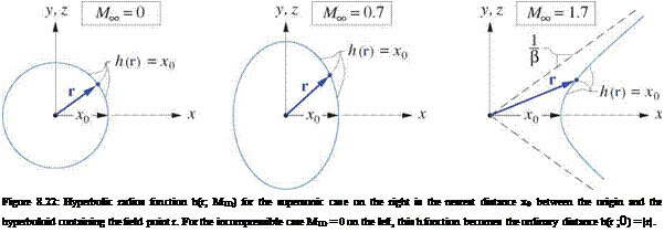
which is the closest distance between the singularity point at the origin and the hyperboloid surface contain­ing the field point r, as shown in Figure 8.22. The term “radius” originates from the observation that for the incompressible case M =0 it reduces to the actual distance function h{r;0) = |r| = Jx2 y2 z2. For a singularity point located at some arbitrary location r’ other than the origin, the hyperbolic radius is obtained by the usual shift of the function’s argument, h(r-r’; ). The equation

h(r-r’; MTO) — 0

therefore defines a Mach cone with its apex at location r’.

Подпись: Figure 8.22: Hyperbolic radius function h(r; MTO) for the supersonic case on the right is the nearest distance x0 between the origin and the hyperboloid containing the field point r. For the incompressible case MTO = 0 on the left, this h function becomes the ordinary distance h(r ;0) = |r|.

Supersonic point source

. Canonical supersonic flow Подпись: (8.144)

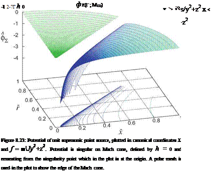
The basic 3D singularity from which all others can be constructed is the supersonic point source, which has the following unit-strength potential or kernel function, plotted in Figure 8.23.

Подпись: a(r) = V2(/>E Подпись: M2 Подпись: <92</>s dx2

The term “source” is a bit misleading here, since this flow-field is not just the usual point source at the origin, but also includes the field source distribution

which is generated by the point source. It’s also important to note that an isolated supersonic source of finite strength is not physical, since its a field has an infinite strength everywhere on its h(r) = 0 Mach cone
surface. The velocity field also has a very strong 1/|r — r’j2 singularity everywhere in the vicinity of the Mach cone surface. A more physical flow-field will be obtained only after a distribution of infinitesimal point sources is superimposed, as will be considered in the following sections.

Supersonic line source

. Canonical supersonic flow . Canonical supersonic flow Подпись: (8.145) (8.146)

Superposition of a line of supersonic point sources (8.144) along the x-axis, from the origin downstream, creates a supersonic line source. This can represent supersonic flow over a body of revolution.

The radial distance r from the x-axis will be convenient to use for axisymmetric potential distributions such as this one. Note that this is a change in notation from elsewhere in this book, where r typically denotes jrj.

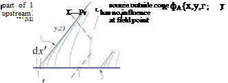
The integration range in (8.145) is restricted to only those point sources on the x-axis which can influence the field point x, y, z. This range is what lies inside the upstream Mach cone emanating from the field point, as sketched in the figure above.

Подпись: фл(х,у,х ; MTO)

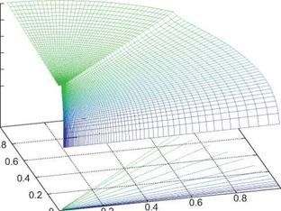
For the case of a unit line-source density Л(х) = 1, we can integrate (8.145) to give the unit line source potential, shown plotted in Figure 8.24.

Note that the highly singular nature of the point source potential has been mitigated to a weak logarithmic singularity for the line source. The strength of the perturbation velocities дфA/дx and дфA/дr, has also been mitigated to a 1/|r — r’j singularity along the origin’s Mach cone where h = 0, and also on the x-axis where r = 0.

Подпись: дф dr Подпись: r=R Подпись: dR dx

The local source line strength Л(х) required to model a body of revolution with area and corresponding radius distributions А(х) = пЯ(х)2 can be determined by same approach used in the subsonic case. Remembering that ф is normalized with the freestream velocity, the flow tangency condition at the body surface is
. Canonical supersonic flow

. Canonical supersonic flow1

Figure 8.24: Potential of a unit supersonic line source extending from the origin downstream.

. Canonical supersonic flow . Canonical supersonic flow

which when rewritten using the unit-strength radial velocity (8.149) gives the required line source strength Л in terms of the body geometry.

Подпись: dR dx A 1

Подпись: (8.151). ndR dA

Л = ‘2ttR-— = — dx dx

Aside from a factor of (Л here corresponds to Л/V^ as defined previously), the line source strength (8.151)

is exactly the same as expression (6.72) for a slender body in incompressible flow. Since Л here also depends only on the total cross-sectional area A(x), it can be used for bodies which aren’t exactly axisymmetric.
Small-Disturbance Supersonic Flows

The Prandtl-Glauert equation is valid for slender supersonic flows sufficiently far beyond = 1. As a minimum, the flow must be supersonic everywhere, with no locally-subsonic regions. Furthermore, the perturbation velocities must be small enough so the quadratic and higher-order terms in the mass flux ex­pansions (8.44)-(8.46) are much less than unity. Because these also scale as Ы’ф or, the validity of the PG equation becomes restricted to flows which are more and more slender as the Mach number increases. This shrinking range of validity with increasing Mach number is indicated in Figure 8.11.

8.8.1 Supersonic flow analysis problem

Подпись: — (M00— 1) (xx + (yy + (zz = 0 Ux + (y Uy + (z nz = 0 Подпись: (Body BC) Подпись: (8.127) (8.128)

The linearized small-disturbance supersonic flow problem has the same governing PG equation and flow – tangency condition as the subsonic case,

but the фхх term now has a negative sign. This fundamentally changes the nature of the solutions, which exhibit waves propagating from the body. It’s also necessary to redefine в so it stays real.

j3 = JM£ — 1 (supersonic flows) (8.129)

8.8.2 2D supersonic airfoil

Small-Disturbance Supersonic Flows
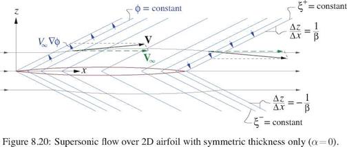
The wave-like nature of supersonic PG solutions is most easily seen in the 2D thin airfoil case, where we drop фуу and set (nx, ny, nz) = (a-Z, 0 , 1). The PG problem (8.127), (8.128) then simplifies to

The { functions are called characteristics, along which the solution is constant in this case. Figure 8.20 shows the perturbation velocities and streamlines for the thickness-only case.

The perturbation x-velocities give the pressure coefficients.

Подпись:c„, – – m,)« – – |[-« + zL+>]

The lift coefficient can then also be computed, assuming the airfoil has Zu — Zi — 0 at x — 0,c.

c£ = j>-Cp n z d(x/c) = J (CPI-CPu)z=0 d(x/c) = I a

Relation (8.136) is the Ackeret equation for 2D supersonic lift. The lift-curve slope is dcg/da = 4/в which can be compared with the 2п/в value on the subsonic side. Interestingly, the supersonic Q is independent of the airfoil shape, since it does not have the q0 camber term of the subsonic case.

The lift can also be obtained from the circulation via the Kutta-Joukowski theorem, which is valid for compressible flows. The circulation is the wake potential jump given by the last form in (8.132).

Подпись: (8.137)

Small-Disturbance Supersonic Flows

L’ = p^T = 2T_ = 2 A </>wake = 4^ Ip^VJc СІ4 C fia

Unlike subsonic inviscid 2D airfoils which have zero drag, supersonic inviscid 2D airfoils in general have nonzero wave drag. This is associated with the oblique waves which carry energy away from the airfoil, and hence is different in nature than the wave drag due to a normal shock on subsonic/transonic airfoils which dissipates energy locally. Using the integral momentum theorem on the contour around the airfoil shown in Figure 8.21, we have

DW = – pV■ n (V-V) ■ Xdl ~ – pxV* фг фх nz dl (8.138)

which can in general be separated into wave drag due to lift and wave drag due to thickness.

D

cdw = J 7^- = {Cdjjt + (Cdw)r (8.139)

2 Poo too C

(c-dji = I a2 = c£ a (8.140)

(Cdjr = j5 ^{{Z’J + iZ’^dix/c) (8.141)

It should be noted that all the above results are valid only for thin airfoils at small angles of attack, since

the small-disturbance approximation was used to derive its governing PG equation. An alternative approach is to use Shock-Expansion Theory based on oblique-shock and Prandtl-Meyer expansion-fan functions (see Shapiro [60]). These do not rely on small-disturbance approximations and hence are more accurate, but they do not apply to general 3D flows. Since most practical supersonic applications have low aspect ratios which result in strongly 3D flow, we will restrict our analysis to the PG equation.

Уф ф z

Compressible 3D far-field

Compressible 3D far-field Compressible 3D far-field Подпись: (8.120) (8.121) (8.122) (8 123) (8.124)

The 3D incompressible far-field potential and velocities, when written using the transformed variables, become applicable to the compressible case,

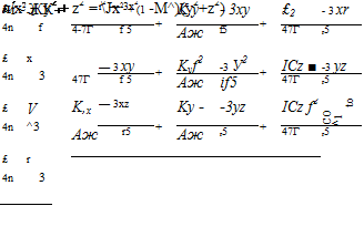
The incompressible 3D far-field analysis of Section (2.12) gives the far-field source £ in terms of the body’s wake momentum defect and drag, and gives the far-field x-doublet Kx in terms of the body’s volume. Noting that both the area and volume scale as в2 in the PG transformation, the transformed strengths for the transformed far-field expansion are given in terms of the physical parameters as follows. Relation (8.114) is also applied to relate the wake displacement area to the momentum area and drag.

s = KA = V^02 = l-V^SrefCDJ2 (l + (7-l)Mt) (8.125)

Kfx = Vo f = Vo V в2 (8.126)

Compressible 2D far-field

Compressible 2D far-field Подпись: (8.105) (8.106) (8.107) (8.105) (8.109)

Since the transformed flow problem is incompressible, we can re-use the far-field expressions for the far – field potentials and velocities which were developed in Chapter 2. For the 2D case we have

The four far-field coefficients can be defined directly from the incompressible definitions, with the reverse transformation immediately included to put them in terms of the physical parameters.

л = V*r* = V*S* e (8.110)

f = Iv^cct = ilLccif (8.111)

= lU(l + ^) = 1+^) (8.112)

Rz = cmo = ^KoC2cmo/l2 (8.113)

A complication in relating Л to the drag coefficient is that at high speeds the boundary layer and wake fluid is heated significantly via friction, which reduces its density relative to the potential flow. The reduced density increases S* relative to Г, as can be seen from comparing their definitions (4.4) and (4.11) for p/pe < 1. An approximate relation between the far-downstream thicknesses is

S* ^ (l + (Y—1 )M*) Г* (8.114)

which follows from the assumption that the wake has a constant total enthalpy, as discussed in Section 1.6. The far-field source (8.110) can then be more conveniently given in terms of the profile drag coefficient cd = 2Г*/с as follows.

A = hA /3 (1 + (7-l)M2 ) = ^ccd /З (1 + (7-l)M2 ) (8.115)

With all the transformed far-field coefficients known, the transformed perturbation potential and velocities can be calculated from (8.105),(8.106),(8.107) at any field point of interest. The physical perturbation potential and velocities are then obtained by the usual reverse transformations:

<Pff

= yd«

(8.116)

дфп

dx

1 dфn

(32 dx

(8.117)

дфп

dy

1 dф^^ /3 dy

(8.118)

дфп

dz

1 dф^^

/3 dz

(8.119)

One complication with this treatment is the far-field contribution of the higher-order compressibility terms in the PP2 equation (8.55), which are ignored in the first-order PG equation. Specifically, the source and vortex parts of (ff in (8.105) have their own field-source distributions as given by (8.1), which then should be included in the fx integral (8.104) above, and the corresponding fz integral as well. This correction is treated by Cole and Cook [59]. The main effect is that an airfoil’s far-field x-doublet now also depends to some extent on its lift, not just on its area.

Subsonic Compressible Far-Fields

8.7.1 Far-field definition approaches

Two approaches can be used to define the far-field for any given compressible flow situation:

1. Define the far-field expansion in physical space. A complication now is that the integrals for the far – field coefficients must include contributions from the field sources. For example, the 2D far-field x-doublet strength of an airfoil represented by source and vortex sheets is

Подпись: 1 V(V-V) • V "2 a?Подпись: x' dx' dz'kx = j (—Xx’ + yz’) ds’ +

where the last integral over the field sources x(x’,z’) would be difficult or impractical to compute in practice.

2. Define the far-field expansion in Prandtl-Glauert space. Now the x-doublet strength is

Подпись: (8.104)Kx = (-Xx’ + yz’) ds’

in which the field source integral does not appear, since X ~ 0 within the transformed flow-field. Existing incompressible-flow estimates for the coefficients can therefore be used. The resulting transformed far – field potential or velocities are then reverse-transformed to obtain the physical potential or velocities. This far-field definition approach is clearly better, and will be used here.