Category Dynamics of. Atmospheric Flight

FORCE AND MOMENT EQUATIONS IN BODY AXES (EULER’S EQUATIONS)

The force equation of motion in FB is [see (5.4,9)]

fg —

with aqb given by (5.3,16). Again particularizing, as in Sec. 5.5, to the case of a stationary atmosphere, (5.3,18) give the required components of acceler­ation. With the aerodynamic force in body axes denoted by ~X~

Подпись: AB —Подпись:Y

Z in accordance with traditional usage, and treating gravity as in Sec. 5.5, the scalar equations become

X — mg sin в = т[й + (qEB + q)w — (r®B – j – r)v]

Y + mg cos в sin ф = m[i> + (rEB + r)u — (pEB + p)w] (5.6,2)

Z + mg cos в cos ф — m[w + (pEB + p)v — (qEn + <l)u]

Again, when the Earth rotation can be neglected entirely, (pBB, qEB, fEB) vanish.

The moment equation in frame Fz is (5.4,12), i. e.

G7 = h7 (5.6,3)

or in body axes,

= YBIGZ = hB + Wghg (5.6,4)

The conventional notation for Gg and hв is

[despite the fact that L is also used for lift (5.5,5)]. In atmospheric flight G normally comes from aerodynamic, propulsive, and control forces; in space flight however, magnetic forces, solar radiation pressure, and gravitational
torques may all contribute importantly to it. The scalar expansion of (5.6,4) is

L = K + qhz — rhy

M = К + rK — phz (5.6,6)

N = К + pK — qh

When mean axes are used, (5.4,28) gives hB, and in that case (5.6,4) can be expressed as

b&b + ^>в-^выв + 2 + 2 &*в^г‘в (5.6,7)

І І

Подпись: +

Note that in (5.6,7) the rotation of the Earth does not appear exphcitly, even though no assumption has been made concerning it. It does however occur implicitly in to, which is the angular velocity of FB relative to inertial space. The matrix expansion of (5.6,7) is

(5.6,8)

Owing to its length, there is little advantage in presenting the full scalar expansion of the complete equation (5.6,8). For the restricted case in which S is neghgible, and there are no rotor terms, that is, for a rigid body, it is

L = Ixp- IyZ(q2 – r2) – Izx(r + pq) – Ixy(q – rp) – (Iy – Iz)qr

М = І£ — I Jr2 – p2) – Ixv(p + qr) – Ivz(r – pq) – (Iz – Ix)rp (5.6,9)

N = Izr – Ixy(p2 – q2) – I, Jq + rp) – Izx(p – qr) – (Ix – Iy)pq

It is usually the case for flight vehicles that Gxz is a plane of symmetry.

In that case Ixy = Iyz = 0, and (5.6,9) simplify to

L = IXP — !-Jr + pq) – (Iy – Iz)qr M = Iyq – Izx(r* – p*) – (Iz – Ix)rp (5.6,10)

N = Izr — Izx(p – qr) – (4 – Iy)pq

Finally, when the axes are principal, Izx as well vanishes, and we obtain the simplest form of the moment equations

L = Ixp- (4 – Iz)qr

M = Iyq – (4 – Ix)rp (5.6,11)

N = Izr — (4 – Iv)pq

THE FORCE VECTOR

The force vector for atmospheric flight consists of two parts, the aero­dynamic reaction (including propulsive force) A, and the weight mg, i. e.

f = A + mg (5.5,3)

In the wind-axis system Fw, the components of A are given by

Подпись: ,zw. (5.5,4)

It is convenient further to subdivide A into the “configuration aero­dynamics” and the propulsive force thus

‘D’

—– j

*

Aw — —

G

+

T

vw

_L_

T

L-1 zwJ

Where D is drag, G is side force, and L is lift. The directions of D, C, L relative to the vehicle are illustrated in Figs. 4.4 to 4.6. The separation of the thrust from the other forces is to some extent always arbitrary, but is nevertheless useful. Any of the components of T may be large when we consider the flight of rockets or of V/STOL aircraft, although in the cruising flight of airplanes only Tx is usually significant. Finally the gravity force is given by

Подпись: and THE FORCE VECTOR Подпись: (5.5,6)

ГОП

In terms of the wind-axes Euler anglesf this becomes, from (4.5,4)

Подпись: w—sin 0,

Подпись:mgw mg cos 0W sin <j>w

cos Bw cos <j>w so that the expanded set of scalar equations is

TXw — D — mg sin 6W = mf (a)

TVw — C + mg cos вw sin <j>w = mV(rEw + rw) (b) (5.5,8)

TZw — L + mg cos dw cos <f>w = —mV(qEw + qw) (c)

The terms rBw and qEw will vanish when Earth rotation is negligible.

The above equations are most conveniently regarded as having the primary dependent variables F, rw, qw. However they are not complete in the sense that the aerodynamic and thrust forces contained in them are functions not only of the above three variables, but also of pw, and of the aerodynamic angles a and /? (see Sec. 4.3). The moment equations and some additional kinematic relations must be used to complete the mathematical system; these are presented in the following sections. Little use has been found for

f The elements of LWy, i. e. the direction cosines of Fjy, can be used as the orientation unknowns instead of the Euler angles, see Sec. 5.2.

the moment equations in the Fw frame, and these are given below only for FB.

FORCE EQUATIONS IN WIND AXES

The force equation of motion is (5.4,9). In wind axes it becomes

iw = macw

with &Cw given by (5.3,11). For the particular case of a stationary atmosphere

(5.3,15) gives the acceleration components, so that the scalar equations of motion are

fxw =

fvw = mV{rEw + rw) (5.5,1)

Szw = -™V(qEw + qw)

Although all the terms of (5.5,1) may be needed for applications to hypervelocity flight, there are numerous exceptions in which the Earth rotation can be neglected. The result is then much simpler, viz.

fxw =

fvw = m^rw (5-5,2)

fzw = – mVqw

Not only is (5.5,2) simpler in form than (5.5,1), but the angular velocities rw and qw that appear in it are those of Fw relative to Earth and not to inertial space, and are themselves correspondingly simpler.

THE REMAINDER OF h*

The remainder of h* ordinarily comes from the motion of hinged parts and from elastic deformation, although there are other kinds of possible relative motion, such as fuel sloshing which is important in liquid-fueled rockets (ref. 5.14). This total remainder is denoted by he. We now show that it is possible always to choose a set of body-axes FB for which he vanishes. These are termed “mean axes” by Milne (ref. 5.2).

Consider two centroidal reference frames FBi and FB^ for which the angular momenta are

hBl = RBlR£l dm + SBl(aBi+ 2 hr‘Bi (a)

*’ (5.4,25)

Ьд2 = J dm + + Ao>)Ba + 2 hr*B2 (6)

Here the summations are the contributions of spinning rotors, R in the inte­grals represents the residual relative motion, and Ato is the angular velocity of FB relative to FBl. The first term of (5.4,256) can be transformed as

Подпись: [Єв2 — J THE REMAINDER OF h*

140 Dynamics of atmospheric flight follows:

THE REMAINDER OF h*H /gil dm “bj 11 /;, Ato^R^ dm Applying (5.4,17) to the last term, we get
he_B; = l^Bjj RbjRbj dm + в у AwjBjj (5.4,26)

It follows that the angular momentum b. eBi of the distortional relative motion vanishes in FB^ if

j dm + -&bx AtoBi = 0

or if

Awjjj = —SBfdm (5.4,27)

Equation (5.4,27) provides the condition that the axis system FB must satisfy if the angular momentum hBj referred to it is to have the form

К=-*1^в + 1Ъив (6.4,28)

І

This condition will be met when FB has the orientation required by TjBiBJt) that satisfies the differential equation [see (4.6,6)]

(5.4,29)

It is not necessary actually to solve (5.4,27 and 29) for LgiBa in order to make use of mean axes. Our concern here is simply to establish their ex­istence. We note that when the body axes are mean axes, the following relations must hold for the distortional motion. Since the origin is the mass center,

J* x’ dm —jy1 dm = J"s’ dm = 0 (a)

and from (5.4,23) (5.4,30)

J” (yz’ — y’z) dm = j (zx! — z’x) dm = J* (xy’ — xy) dm = 0 (6)

in which the prime denotes the distortional component of the velocity relative to FB. The use of mean axes, and the consequent elimination of distortional contributions to h* has the effect of eliminating the main inertial

coupling between the distortional degrees of freedom and those of the rigid body. Some coupling still remains through jP however, see (5.6,7).

ROTATING SUBSYSTEM

When the relative motion in question (i. e. of the system w. r.t. FB) is that of a rigid rotating subsystem (such as an engine rotor or propeller in an air­craft or an inertia wheel in a spacecraft) with angular velocity wr relative to the main body, then we have, over the spinning component,

®в =

where Kfg is the position vector of a mass element relative to an origin anywhere on the axis of rotation. Ordinarily the mass center of the spinning body lies on its axis, and this is the natural choice of origin for RrB. In that case it is easily shown (an exercise for the reader) that the contribution of the rotor to h*, denoted hr, is

Кв=-?тв*»тв (б-4-24)

where •FTB is the inertia matrix of the rotor with respect to centroidal axes parallel to those of FB. If moreover the spin axis is a principal axis of inertia of the rotor the vector hr is collinear with tor, and has magnitude Irof where IT is the moment of inertia of the rotor about the spin axis. Naturally, there is one term like (5.4,24) for each rotor.

THE ANGULAR MOMENTUM

With components in FІг the angular momentum of the general deformable body is from (5.4,12c), on converting to matrix notation,

It is not convenient, as will be seen later, to have the angular momentum components referred to fixed axes. In fact we want its components along the axes FB, attached to the moving vehicle. From (4.6,10)

Rj — "Ь Фв®в) (5.4,14)

whence (5.4,13) gives the components of h in FB as

hj? = LBfhz =|bB/RjLJBRB dm + | JjbiRjLibG)bRb dm

Now the matrixR transforms according to the rule (4.7,4), so that =

RB and we get for hB

hB =|r#RBdm – l-JR/^tO/jR/^ dm (5.4,15)

When the body is rigid, R/; = 0, and the first term vanishes. [Note that JR* dm vanishes in any case because the origin is the mass center, see (5.4,116).] The second term of (5.4,15) is therefore identified as the “rigid-body component” of h, and the first term as the “deformation component.” To evaluate the second term, we note that шЕ = — lw (Since wxE = — R x со) and hence

THE ANGULAR MOMENTUM(5.4,16)

Since (aB is constant with respect to the integration, we may write

‘ |®тД. в**>в f^m — – Fb^b (5.4,17)

Подпись: where

JFB= – RBRB dm (5.4,18a)

(note the identity RR = RyRI — RRT). After expansion of (5.4,18a) and integration we get

(5.4,186)

The two notations for the elements of^ given in (5.4,186) are both traditional and in current use in flight dynamics literature. These elements are the

138 Dynamics of atmospheric flight moments and products of inertia, i. e.

Подпись: (y2 + z2) dm, etc.THE ANGULAR MOMENTUM

THE ANGULAR MOMENTUM Подпись: etc. Подпись: (5.4,19)

I.

Note that the inertia matrix transforms according to (4.7,4), so that for two reference frames FBi and Fb* we have

THE ANGULAR MOMENTUM(5.4,20a)

For any 1Si, there always exists a transformation IіВіВг that produces a diagonal matrix B„ (see ref. 5.1). FB is then a set of principal axes, for which the products of inertia all vanish. When the vehicle has a plane of symmetry, then the x and z principal axes lie in it. If the body axes FB are obtained from the principal axes by a rotation є about Су, the elements of ■FB are found from (5.4,20a) to be

Ix = Ix cos2 e + Іг sin2 e

Подпись:Iz = Ix sin2 Є + I cos2 e Jzx = W-,, – ht) sin hv = I„ = 0

where the subscript p denotes principal axes.

Let us denote the deformation component of h by

THE ANGULAR MOMENTUM(5.4,21)

so that (5.4,15) gives the total angular momentum

Подпись: (5.4,22)Кв — Кв + ^выв

From (5.4,21) we can evaluate h)} as

EQUATIONS OF MOTION OF AN ARBITRARY SYSTEM

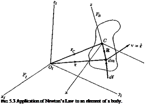
Подпись: FIG. 5.3 Application of Newton’s Law to an element of a body.

The equations of motion result from the application of Newton’s laws of motion to the material system that constitutes the flight vehicle. Consider

an element of mass dm, and an inertial frame of reference FT (see Fig. 5.3). (Since only one reference frame is used in the following argument, no identi­fying subscript is appended to the vector symbols. The subscript I should be understood.) Newton’s second law provides the equation of motion of dm, i. e.

di = r dm — v dm (5.4,1)

Here di is the resultant of all the forces acting on dm, r is its position vector, and v its velocity. In this form, the equation is valid only in an inertial frame of reference.

Taking the cross product of (5.4,1) with r yields the moment equation

r x di = r x v dm (5.4,2)

Подпись: It follows that Подпись: dh' = r x v dm Подпись: (5.4,3)

Now let the angular momentum of dm w. r.t. О be defined as

— (dh’) = (r x v r x v) dm dt

= (v x v + r x v) dm

— (dll’) = r x v dm dt

which is the r. h.s. of (5.4,2). We therefore have

II

55

43

(5.4,4)

where

dG’ = r x df

(5.4,5)

is the moment of df about 0.

We now integrate (5.4,1) and (5.4,4) for a system of particles comprising a general deformable body of mass m. First we note that the mass center G of

the body is located at rc, given by

mrc =jrdm

(5.4,6)

Differentiating once yields

/*

mvc = 1 r dm

(5.4,7)

and a second time

«Ир = v dm

(5.4,8)

where vc and ac, are respectively the velocity and acceleration of the mass center relative to Fr The integral of (5.4,1) is obtained from (5.4,8) as

Подпись: f = m&c(5.4,9)

where f = j df is the vector sum of all the forces acting on all the elements. Since the internal forces, those which one element of the system exerts upon another, occur in equal and opposite pairs by Newton’s third law of motion, they vanish from J df: f is then the resultant external force acting on the system m. Similarly, the integral over m of (5.4,4) is simply,

G’ = – h’ (5.4,96)

dt

where G’ = j" r x df is the resultant external moment about O, and

h’ = J*r x v dm (5.4,10)

is the resultant angular momentum about O. Let

Подпись: (5.4,11a)

Подпись: Since v x v = 0,

r = rc + R

as shown on Fig. 5.3. Note that from (5.4,6)

Подпись: (5.4,116)J R dm = 0

Then we may expand (5.4,96) as follows:

jVc+R) x«*f=| J (rc – fE) x t dm Since rc is constant, it can come outside the integrals, to give

v dm + — Jr x v dm

EQUATIONS OF MOTION OF AN ARBITRARY SYSTEM EQUATIONS OF MOTION OF AN ARBITRARY SYSTEM Подпись: (5.4,12)

From (5.4,8) and (5.4,9) the leading terms on the l. h.s. and r. h.s. are seen to be equal, so the equation reduces to

are, respectively, the moment and angular momentum about <7. Note that (5.4,96) has the same simple form as (5.4,12) even though the former is referenced to a fixed point in inertial space, and the latter to a moving point, the mass center. This simple form does not hold, for arbitrary motion of the systems, for any moving reference point except the mass center.

Equations (5.4,9) and (5.4,12) are the two fundamental vector equations, equivalent to six scalar equations, that relate the “gross” motion of the body to the external forces that act on it. The description of the “fine” motion (distortion and articulation) requires additional equations that are given subsequently.

INERTIAL ACCELERATION

We have two particular requirements for the inertial acceleration of a particle in a moving reference frame: one is for the Fw or FB components of the acceleration of C or 0V, the vehicle mass center, and the other is for the FB components of the acceleration of a particle in arbitrary motion relative to the vehicle. Other reference frames may be of interest for application to special dynamics problems, or for the analysis of navigation and guidance systems in which expressions are needed for the outputs of accelerometers mounted on inertial platforms that are oriented in accordance to some particular navigation scheme. The two applications first mentioned above are developed here; and as a matter of interest, we give also the formulation needed for a particular navigation application.

Acceleration of G. The basic equation for the inertial acceleration of the mass center is (5.1,7), in which the moving point is 0r, in the rotating frame Fe. r’ is then the velocity of the mass center relative to Earth, which we have denoted E. We assume here, as in Sec. 5.2, that the Earth’s axis is

fixed in inertial space, and that <«> = 0. Thus the acceleration a0 of the origin of FE is the centripetal acceleration associated with Earth rotation. A numeri­cal comparison shows that this acceleration is usually negligible when com­pared with g. It is zero at the poles, and of order 1/1000 g at the equator (sea level). The same holds true for the centripetal acceleration dwr’ of

(5.1,7) —i. e. it is usually negligible. Of the two terms that remain in (5.1,7) r’ = Vе and the Coriolis acceleration is 2{ЬЕХК. The latter depends on the magnitude and direction of the vehicle velocity, and is at most 10% g at orbital speed. It can of course be larger at higher speeds. This term must therefore be kept in the mathematical model, even though it is at times negligible. Finally then, the When the atmosphere is at rest, W = 0 and the components of (5.3,11) are

Подпись: cr= t

Подпись: (5.3,15)

INERTIAL ACCELERATION Подпись: 4w)

— V (fEw + rw)

[Note that toK and biW are both angular velocities relative to inertial space, and that the sum (rKw + r,,-) for example, is not the resultant yaw rate of Fw relative to Fj, as one might be tempted to infer from (5.3,15).]

INERTIAL ACCELERATION INERTIAL ACCELERATION

For the frame FB, the same procedure yields instead of (5.3,11)

= w + (p + PEB)V – (? + W

Acceleration of a Particle in FB. A particle having coordinates (x, y, z) in FB has inertial acceleration components in the directions of the axes of FB given by (5.1,8), in which a0 is the inertial acceleration of the origin of FB and (p, q, r) are the components of ы. Since the origin of FB is the vehicle mass center then a0 = ac and its components are those given above in (5.3,18). The required equations are then obtained by substituting (5.3,18) for a0 in (5.1,8).

INERTIAL ACCELERATION

The Navigation Case. From the general relations already given, it is a straightforward, although tedious, calculation to derive the equations for the acceleration components aF of a moving particle. This particular set of components is that measured by an inertial navigation system in which accelerometers are mounted on a stabilized platform that is “Schuler tuned” to maintain one axis vertical, and is “torqued” to maintain one horizontal

axis directed north. In the navigation application, the accelerations of interest are very small, and are in effect integrated twice over long periods of time to give position. Thus the small centripetal acceleration [the last term of

(5.1,7) ] is not negligible, and the complete equation must be used. The acceleration of the origin of Fv (which may be taken to be the location of the inertial platform in this application) is then [cf. (5.3,8)]

= Vee – {G>B<bEkrSt)E + 2(aEEYEE (5.3,19)

where kF is a unit vector on Gzv, and the second term is the centripetal acceleration previously neglected. After transforming to Fv, i. e. aoF = L№a„s, (5.3,19) gives B

r = V*F + (&F – G>E)vEr – (G>E&EkrSl)r + 2<aErEr (5.3,20) tarv and <aEv are given respectively by (5.2,4) and (5.2,1), and from (5.3,1)

Подпись:Подпись: (5.3,21)‘ SIX ‘ Sift cos X. —St

The components of the unit vector kF in Fr are of course [0, 0,1]. After substituting the above expressions into (5.3,20) and expanding the mat­rices, the following system of equations in (M, X, ft) are obtained:

a — SIX + 2MX + St sin X cos X{a>E + /і)2

a0vr = St cos Xfi + 2(a)E + fi)(Sl cos X — SIX sin X) (5.3,22)

a0zr = ~St + тг + St, cos2 X{a>E + ft?

When accelerometers provide measurements of the l. h.s. of (5.3,22), a navigation computer can in principle solve the three equations for the geocentric position (St, X, ft). For horizontal flight or when St can be ne­glected, the result is simpler, i. e.

Подпись: (5.3,23)a0^ = SIX – f St sin X cos X{wE – f ft)2 a0^ — —St cos Xja — 2(coE + {t)SlX sin X

INERTIAL ACCELERATION Подпись: (5.3,24)

This is a pair of equations for the latitude and longitude of the vehicle. To mechanize them for analog or digital computation, they would be more conveniently rearranged as

INERTIAL ACCELERATION

POSITION, VELOCITY, AND ACCELERATION OF THE VEHICLE MASS CENTER

POSITION AND VELOCITY RELATIVE TO THE EARTH

The location of the vehicle mass center relative to Earth is given by the spherical polar coordinates ЗІ (geocentric radius), ц (longitude), and X (latitude). Their rates of change are related to the Fv components of velocity relative to Earth by (see Fig. 5.2)

Я = – Vе.

ZT

Подпись: (5.3,1)u —___ 1__ Vе

* Зі cos X y*

A = —

The components of E are in turn given by [see (4.2,1)]

YEy = I‘vw(^w = – ЦтвСУв "Ь Wв) (5.3,2)

where

~V

1__

Yw —

0

; Ww =

W

n Vw

_0_

w

Lrr zwJ

~u

Yb =

V

; WB =

K

w_

Wz.

and ¥ is the airspeed of the vehicle, i. e. its speed relative to the atmosphere. When the atmosphere is at rest relative to Earth, W = 0 and (5.3,2), (5.3,3), and (4.5,4) yield

VеXp = V cos 0W cos y>w

VEyy = V cos 6W sin y>w (5.3,4)

VEZp = —V sin 6W

Substitution of (5.3,4) into (5.3,1) provides the polar coordinates in the

130 Dynamics of atmospheric flight more convenient forms

0t = V sin ew
V

ft = — cos dw sin %pw sec A (6.3,5)

Я = — cos 0W cos y>w

Using the body-axis velocity components an alternative system of equations

is

Подпись: * m ' "u № cos A — LFB V . -st . _w_ (5.3,6)

When the motion considered takes place over only a small portion of the Earth’s surface, the latter may be regarded as locally flat, and the vehicle position is then more conveniently referenced to a frame Fe located in its immediate vicinity—for example, at the initial point of the trajectory. In this case Fv may be assumed parallel to Fe, and the position coordinates of the mass center (xE, yE, zE) are governed by the differential equations

xE = V cos 6W cos y>w

yE = V cos Ojfr sin iffy (5.3,7)

iE = — V sin 6W

THE DIRECTION COSINE RATES

When the direction cosines of the moving frame are used instead of the Euler angles to define its orientation relative to Fv, then the differential equations needed follow directly from (4.6,7). Let ^BF = [iw] (the same treatment holds for Then from (4.6,7)

Подпись:(5.2,11)

These constitute nine differential equations for the nine l(j. Actually only three of the nine are independent (a rigid body has only three rotational degrees of freedom), and the additional six equations provided by (4.4,8) reduce the number of independent l{j to three. In the force equations given later, the direction cosines that would replace the Euler angle terms are those for the angles between the moving axes of Fw and zv, i. e. (with now denoting components of L(</(,) l13, l23, and l33. The differential equations for these are, from (5.2,11),

Ьз — Ш33 QI33

tu = – Rl13 + Pl33 (5.2,11a)

І3З = Ql 13 R^23

and for some problems only these three direction cosines are needed. Whether

direction cosines or Euler angles are preferable in any particular application depends on the situation, and on the kind of computing machinery to be used.

THE AERODYNAMIC ANGLE RATES

We shall find it convenient later to have the angular velocity of FB relative to Fw expressed in terms of the derivatives of the aerodynamic angles.

THE DIRECTION COSINE RATES
Let jB and 1%, be unit vectors in the directions of GyB and Czw, respectively. Then it follows from the definitions of oq. and /3 (Sec. 4.3) [and an argument like that for (5.2,3)] that the angular velocity of FB relative to Fw is

The group of three equations actually wanted subsequently is (5.2,14a) and (5.2,15).

THE DIRECTION COSINE RATES Подпись: toF)

Since (5.2,12) may alternatively be written

it follows that (5.2,13) through (5.2,15) apply equally when the angular velocities of FB and Fw are relative to Fv instead of FI. Then the lower-case (p, q, r) are replaced in them by (P, Q, E).