Our heavyweight helicopter equal in the world does not have
In Rostov started production of the most load-lifting rotary-wing car The Russian holding «Helicopt[...]

Everything about aircrafts and helicopters. News and events in aviation worldwide. Civil, transportation, military helicopters and airplanes.

Everything about aircrafts and helicopters. News and events in aviation worldwide. Civil, transportation, military helicopters and airplanes.

Everything about aircrafts and helicopters. News and events in aviation worldwide. Civil, transportation, military helicopters and airplanes.

Everything about aircrafts and helicopters. News and events in aviation worldwide. Civil, transportation, military helicopters and airplanes.


This is an equally simple method of utilizing the transpiration concept which is especially applicable to viscous flow solvers, but the manner of treating boundary conditions on surfaces is different. For example, in the flow analysis w ith Navicr-Stokcs equations, the по-slip condition is imposed at live solid surface by enforcing zero values of all three components of the contravanant velocity vector defined as U = D£/Di. V = D^/Dt. W « D£/Dt. The curv ilinear, non-orthog – onal coordinate system follows the structured computational grid lines. For example, let rj-gnd lines (thus V contravanant clocity component) emanate from the surface of the 3-D object under design consideration. In this inverse shape design concept, the surface pressure distribution, which is obtained from the specified pressure coefficient distribution, is enforced iteratively together with U = W = 0. Tins can he done readily in any existing Navicr-Stokcs flow analysis code 11541- It will result in the contravanant velocity vector component. V. becoming non-zero or ihc surface. Hence, the surface will have to move with iterations or time steps until the convergence is reached, that is. until V « 0 is satisfied on the final surface configuration. This will require that ihc computational grid be regenerated with each update of the surface. Thus. Ihc aerodynamic parameters need to be transfered between old and new grid points by an accurate 3-D interpolation.
|
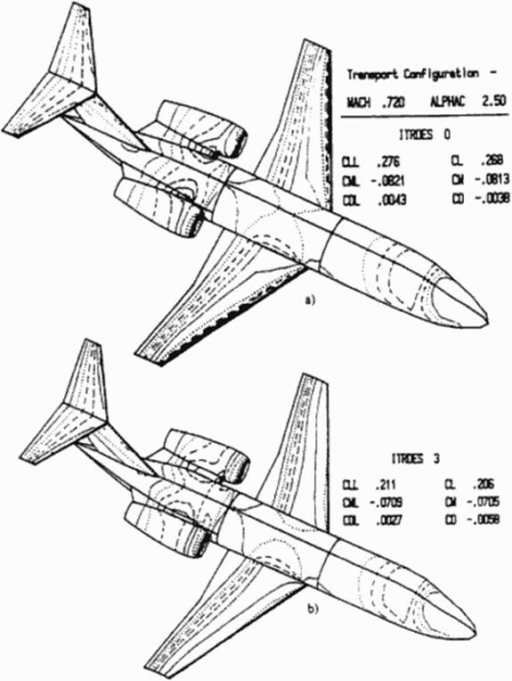
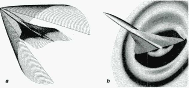
Figure 72 Inverse design of an entire business jet configuration using a high order surface panel code and indirect surface transpiration concept can be performed on a personal computer in less than one hour: a) before, and b) after three optimization cycles enforcing the desired surface pressures. Notice improvements in aerodynamic coefficients {153]. |
This design method will provide for a time-accurate motion of the solid boundaries if the code is executed in a time-accurate mode. For example, it is possible with this method to design a flexible 3-D shape that maintains an essentially steady surface pressure distribution in an otherwise unsteady flow. Specifically, it is possible to determine the correct instantaneous values of local swelling and contraction of a "smart* material coating on the surface thus creating the smart or contmuously-adaptable aerodynamic shape design
This is one of the most common and oldest methods for aerodynamic shape inverse design. Like any iterative technique, it requires an initial guess for the aerodynamic shape Then, using an in – viscid flow-field analysis code with desired surface tangential velocity components enforced will result in non-zero values of the surface normal velocity component. The objective is then to find a configuration that has zero velocity components normal to the final body surface. The computed normal velocity components. v#. are therefore used to modify the shape of the initially guessed configuration using a surface transpiration analogy. The new surface shape is predicted by treating the old surface as porous, hence fictitiously injecting the mass (p vn) normal to the onginal surface so rival the new surface becomes an updated stream surface. The local surface displacements. Дп, can be obtained from mass conservation equations for the quasi two-dimensional sections (stream tubes) of the flow-field bounded by the two consecutive cross sections of the body surface, the onginal surface shape, and the updated surface shape displaced locally by Дл j 149]- (153J. Starting from a stagnation line where Дп,.^** 0.0 and Дл,.| «0.0. separate updating of
the pressure surface and the suction surface can be readily performed by solving for Діц* and Дп, j+t from a Ы-diagona! system. With the classical transpiration concept, normal surface velocities can be computed using any potential flow solver including a highly economical surface panel flow (I52J. (I53J analysis code Figure 72. The indirect surface transpiration method works quite satisfactory in conjunction with Euler and even Navicr-Stokes equations barring any shock waves or flow separation A drawback of this approach is that during the repetitive surface updating using this method, the updated surfaces develop a progressively increasing degree of oscillation. This can be eliminated by periodically smoothing the updated surfaces with a least – squares surface fitting algorithm.
There arc many reliable and relatively fast 3-D flow-field analysis codes in existence It would be highly economical to utilize these analysis codes in an inverse shape design process. This would require development of a short and simple design code that can utilize any of the existing flow-field analysis codes as a large, exchangeable subroutine One very simple method for developing such a design code is based on utilizing an elastic membrane as a mathematical model. This concept treating those parts of the surface of the aerodynamic flight vehicle that are desired to have a specified surface pressure distribution as a membrane loaded with unsteady point-forces. ACp. that arc proportional to the local difference between the computed and the specified coefficient of surface pressure. Under such an unsteady load the membrane will iteratively deform until it assumes a steady position that experiences zero forcing function at each of ihc membrane points. Since this is a general non-physical concept for modeling die unsteady damped motion of the 3-D aerodynamic surface, any analytical expression governing damped motion of a continuous surface will suffice. Garabedian and McFaddcn [147] suggested a stmplc second-order linear partial differential equation as such a model where ACp is proportional to the local surface slopes and curvatures.
Ал + P, • Д-Дл + P2 * + P, • -^-A/i + P4 = p5 ACp (72)
fir Э y‘
Here, the unknowns arc the local normal surface displacements, An. If the surface grid point in question is on the upper surface. = 1.0. if on the lower surface. (i5 = -1.0 The remain-
 |
ing coefficients through P4 are user-specified quantities that can accelerate the approach to a steady state. This partial differential equation can be discretized using finite difference representations for the partial derivatives. This leads to one pcnta-diagonal system or a sequence of two three-diagonal systems of algebraic equations that can readily be solved for the unknown normal surface modifications. Дп,. This simple technique was successfully used to design isolated 3-D transonic supercritical wings [148] with a 3-D full potential code (Figure 71) as the flow analysis module. A simplified version of this concept (with Дг instead of Дп) was used to design engine nacelles and wing-body configurations [ 149). The initial guess for the shape of a 3-D body does not have to be close to the final configuration for this method to work. Although requiring only 30-100 calls to a flow-field analysis code when using a panel code or a full potential equation code, the stiffness of the iterative matrix in the present formulation of the elastic membrane concept increases rapidly with the non-linearity of the flow-field analysis code used. This means that when using Euler or Navicr-Stokcs flow-field analysis code we will need between two and three orders of magnitude more calls to the flow-field analysis code than when using a simple linear panel code. For example, a two-dimensional airfoil shape inverse design with this method utilizing a Navicr-Stokcs flow analysis code may require over ten thousand calls to the Navicr-Stokes code [1501.
Figure 71
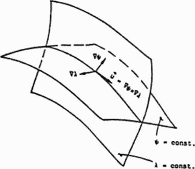
One of the fastest known inverse design techniques is based on a stream function formulation 1142]. The inviscid. compressible, steady flow around a given 3-D configuration can be predicted by solving for two stream functions. ЧЧк. у.г) and A(x. y.z) (I42)-| 146) (Figure 70). For the purpose of inverse shape, design this formulation can be inverted. That is. two quasi-lincar second order coupled partial differential equations of the mixed elliptic-hyperbolic type can be derived These two equations treat the x-coordinate and the values of Ч'(х. уд) and A(x, y.z)or their derivatives as known quantities on the, as yet. unknown solid surface of the 3-D configuration, while treating values of у = y(x,4#.A) and r = /.(х. Ч’.Л) for every 3-D streamline as the unknowns Thus, the result of a numerical integration of this inverted system are the y-and-z coordinates of the 3-
D streamlines. Those streamlines that correspond to the specified surface values of Ч'(х. уд) and Л(х, уд) are recognized as the desired 3-D aerodynamic configuration.
|
|
|
|
– jtVv * VXuM – (J4a – f/f A – !(*, – v, X*i ~ *.)!
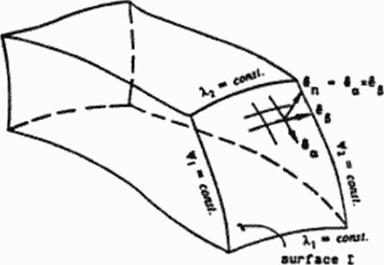
Figure 70 Geometrical interpretation of mass flow rate through a stream tube bounded by two pairs of stream surfaces (144).
A computer code that implements this technique converges very fast because it implicitly satisfies mass at every iteration step thus avoiding the need for integrating the mass conservation equation. Moreover, such a code can be executed in an analysis mode when Dirichlet boundary conditions for ЧЧх. уд) and A(x. y.z) arc specified at every surface point, or in its inverse design mode when Neumann boundary conditions for H^tx. y.z) and A(x. y.z) are specified at every yet unknown surface point. Despite its remarkable speed of execution, robustness and the fact that the entire field of 3-D streamlines is obtained as a by-product of the computation. the SFC concept has its serious disadvantages. This inverse design method requires development of an entirely new code for the solution of the two Strcam-Function-as-a-Coordinate (SFC) equations. The method is not applicable to viscous flow models, it suffers from the difficulties of the geometric muluvaluedness of the stream functions, and is analytically singular at all of the points where die Jacobian of transformation fF. A.Oy (x. yz) become /его (I42J. This occurs ai every point where the x-component of the local velocity vector is zero which can happen at a number of points whose locations we do not know in advance. Consequently, the SFC method is recommended only for the inverse design of smooth 3-D configurations where preferably there arc no stagnation points (3-D duct (146]) or where we are willing to neglect the designed shape in the vicinity of the leading and trailing edges
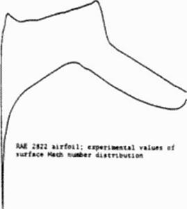
Once the global aerodynamic parameters (inlet and exit pressures, temperatures, and flow angles) have been specified, the next objective is to determine the best way to distribute aerodynamic quantities on the yet unknown configuration. Since the inverse shape design is based on the specified ("desired" or “target’ ) surface pressure distribution, the common dilemma is the choice of the "best” surface target pressure Specifically, it would be desirable to determine the best pressure distribution on the surface of the yet unknow n configuration so that the acrody nam – ic efficiency is maximized by minimt/.ing all possible contributions to the entropy generation in the entire flow-field. From the specified surface distribution of flow-field parameters it is possible to discern only certain aspects of the boundary layer. It is well known that the separated boundary layer significantly increases flow-field vorticity and. consequently, the viscous dissipation function, entropy generation and aerodynamic drag To minimize these effects the desired surface pressure distribution can first be cheeked for possible flow separation before it is further used in the aerodynamic shape inverse design A very fast method for detecting (low separation has been recently proposed [ 141J. It is based on the fact that the rate of change of flow kinetic – energy reaches Us minimum at the separation point. The kinetic energy can be calculated from the surface pressure distribution by assuming that pressure docs not change across a boundary layer. The flow separation detection code is short and very simple since it involves algebraic and analytic expressions only. Thus, the surface pressure distribution, either specified by the designer or obtained while using an optimization process, can be quickly cheeked for possible flow separations (Figure 69) before it is actually enforced.
 |
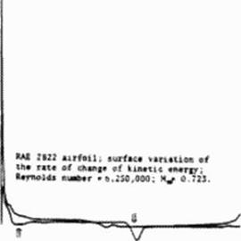 |
Figure 69 Detection of flow separation locations from the specified or measured surface pressure distribution [141]. Arrows point at experimentally found locations of the flow separation points. Our code predicts separation to occur at the minimum of the curve representing the local rate of change of surface flow kinetic energy.
This a pnori checking can be automatically followed by the minor modifications of the local surface pressure distribution with the objective of moving the flow separation points further downstream. The updated surface pressure distribution can be re-checked for the locations of the flow separation points. This checking/modiftcaiion procedure can be repeated until the separation points cannot move downstream any more This procedure is extremely fast since it is accomplished without a single call to the flow-field analysis code.
G. S. Dulikravich
The Pennsylvania Stale University, University Park, PA, USA
10.1 Introduction
Aerodynamic problems are defined by the governing partial differential or integral equauons, shapes and si/cs of the (low domains, boundary and initial conditions, fluid properties, and by internal sources and external inputs of mass, momentum and energy. In the case of an analysis (direct problem) we are asked to predict the details of a flow-field if the shapc(s) and size($) of the object(s) arc given In the case of a design (inverse or indirect problem) we are asked to determine the shape! s) and sizc(s)of the aerodynamic configuration! s) that will satisfy the governing flow-field cquanon(s) subject to specified surface pressure or velocity boundary conditions and certain geometric constraints (ІЗОН 138). The entire design technology is driven by the increased industrial demand for reduction of the design cycle time and minimization of the need for the costly a posteriori design modifications.
Aerodynamic inverse design methodologies can he categorized as belonging to surface flow design and flow-field design. Surface flow design is based on specifying pressure. Mach number, etc. on the surface of the object, then finding the shape of the object that w ill generate these surface conditions. How-field design enforces certain global flow-field features (shock – free conditions, minimal entropy generation, etc.) at every point of the flow-field by determining the shape that will satisfy these constraints. An arbitrary distribution of the surface flow parameters or an arbitrary field distribution of the flow parameters could result in aerodynamic shapes that either cross over ("fish tail" shapes) or never meet ("open trailing edge" shapes) These problems can be avoided by appropriately constraining the surface distribution of the flow parameters (139).
li should be pointed out that inverse methods for aerodynamic shape design are capable of creating only point-designs, that is. the resulting shapes will hac the desired aerodynamic characteristics only at the design conditions. If the angle of attack, free stream Mach number, etc. in actual flight situations are different from the values used in the design, the aero dynamic performance will deteriorate sometimes quite dramatically. For example, when designing transonic shock-free shapes with a surface flow design method, the resulting configuration could have a mildly concave part of its surface locally covered by the supersonic flow indicating the existence of a "hanging shock" or a "loose-foot" shock [139) even at the design conditions. At off-design, the hanging shock attaches itself to the aerodynamic surface causing a boundary layer separation. Consequently, it is more appropriate to design shapes that have a weak family of shocks (140) since such designs have been found not to increase the shock wave strengths appreciably at off-design conditions.
In this chapter, we will focus on briefly explaining only these aerodynamic shape inverse design concepts that arc applicable to the design of three-dimensional (3-D) high speed configurations. An attempt will be made to focus on the techniques that have been found to be cost effective, reliable, easy to comprehend and implement, transportable to different computers. and accurate.
The development of conventional high speed transport configurations like the generic HSCT configuration may still face crucial technology problems resulting in reduced chances to operate economically, as it is critically reviewed in various chapters in this book. New concepts, on the other hand, are emerging, but they must be studied in great detail using reliable theoretical, numerical and experimental analysis tools before any project can be laid out for development of a first aircraft.
All-body and all-wing configurations
From the viewpoint of using the presented geometry generator for support of such new concepts, it seems that promising new configurations can be generated if the two types of shapes, axially and spanwise defined components, are not any longer restricted to their traditional roles of representing fuselage and wing, respectively. There is rather an attractive alternative emerging by either type of component taking over both functions:
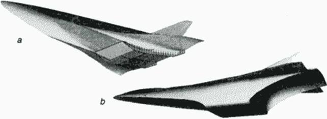
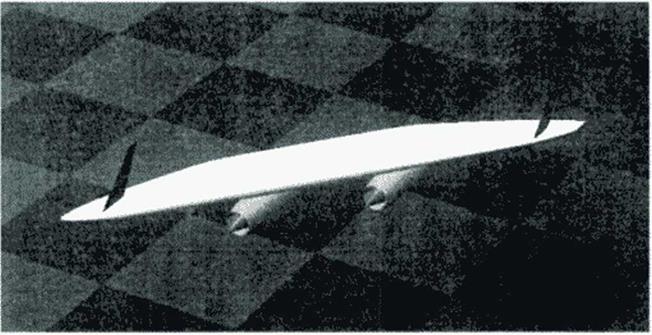
All-body aircraft as well as all-wing configurations arc limiting cases where either wing or fuselage is vanishing and the remaining component taking over both functions which are providing volume as well as lift. Wavenders as illustrated in the previous book chapter are fully integrated configurations; guided by the outlined knowledge base of inverse design it is now relatively easy to create arbitrary direct design cases with wavender characteristics (II5J, there is just no "on-design" condition flow field coming with the design geometry. Suitable choice of geometry parameters to simulate inverse design cases but allow ing a 4D optimization extension as outlined above most likely will lead to further improvements. Generic hypersonics asks for integrated configurations, favorably based on the wavender concept: Direct geometry generation using cither the wing tool (Figure 67a) or the body tool (Figure 67b) for the integrated wing body components can solve this task.
|
Figure 67 Aerospace plane configuration geometry models with wing-body-propulsion integration. |
All-wing or Flying Wing aircraft ha* several advantages reviewed in other chapters of this book; here its attractivity for both aerodynamics and structures in high speed flight just means that we may focus on case studies to model a variety of such Flying Wings as input for detailed analysis in a multidisciplinary approach.
Oblique Flying Wing
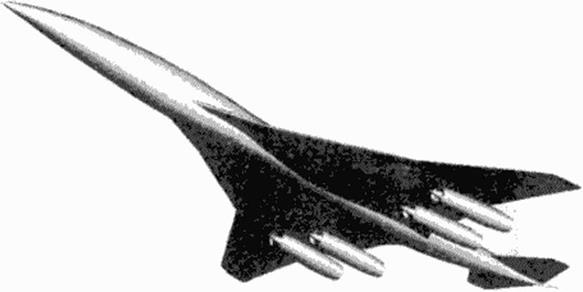
A shape with a relatively simple geometry at first sight is the Oblique Flying Wing (OFW). an ultimate example of adaptive geometry by adjusting the yaw angle of the whole configuration (exept the engines and control surfaces) to the vary ing flight Mach numbers (Figure 68). After several conclusions about the attractivity of this concept in this book, the two final chapters arc entirely devoted to the OFW. In the last chapter some studies are presented using our geometry software for OFW definition. Challenging tasks for systematic geometry parameter fine tuning emerge from the obtained results. Ongoing work will profit from a combination of this geometry generator w ith optimization tools as outlined in the following chapters.
|
Figure 68 Oblique Flying Wing model, with control surfaces and propulsion adjusted to the flight direction. |
9.5 Conclusions
Software for generic aerodynamic configurations has been developed to support the design requirements in the high speed regime. Based on simple, explicit algebra a set of flexible model functions is used for curve and surface design which is tailored to create realistic airplanes or their components with various surface gnd metrics. The explicit and non-iterative calculation of surface data sets make this tool extremely rapid and this way suitable for generating whole series of configurations in optimization cycles. The designer has control over parameter variations and builds up a knowledge base about the role of these parameters influencing flow quality and the aerodynamic performance coefficients. Gasdynamic relations and other model functions allow for the gradual development of our design experience if generic configurations arc used as boundary conditions for numerical analysis with mature CFD codes. Experimental investigations arc supported by CAD data which are delivered from the same geometry inputs as used for preprocessing numerical simulation. With efficient geometry tools available to the designer, the development of interactive design systems for not only aerodynamic but multidisciplinary optimization gets additional momentum.
The above case study, to be further used for a refined analysis and design parameter identification. is just a modest example compared to the needed studies in the development of industrial software suitable for the envisioned multidisciplinary quality as outlined in the first book chapters. With the proven flexibility of the ideas developed here, a larger scale software development at industry, aerospace research establishment and university institutes has picked up the basic el – степь and merged them in their applied software systems:
At Daimler Ben/ Airbus aircraft industry a software system was developed as a preprocessor for multiblck structured grid generation around complete aircraft (126). The fast algebraic definition of arbitrary surface metrics is ideal for application in multiblock/multigrid CFD analysis; many case studies exploiting the richness of possible configuration topologies with this approach have been carried out. Refinements in the algebraic gnd generation tools for optimum multiblock grid spacing have been implemented and complex transonic transport aircraft configurations with suitable grid blocks have been generated and used for CFD analysis.
Parametric studies of supersonic transport aircraft w ings have been performed at DLR German Aerospace Research Establishment (127). Sensitivity studies are earned out and a multi-point optimization design method is being worked on using some of our basic functions and curves. Results are obtained for conventional and new configurations, w ith optima found for relative positioning of the different components.
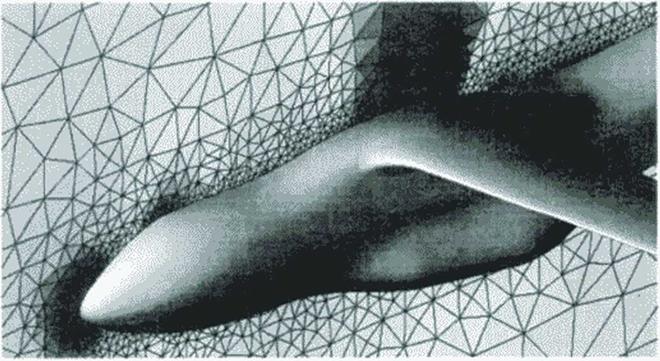
The emergence of new programming languages and faster and more powerful graphic workstations with larger storage capacity gave rise to the development of a new and completely interactive version of this geometry generator (128). Definition of a complex case study for a combined theoretical, numerical and experimental investigation sets various tasks for the new system to serve as a preprocessor for different CAD systems. These systems arc needed for wind tunnel model construction (CAT1A) and for unstructured CFD grid generation (ICEM). The latter is needed for performing Euler and Navier Stokes analysis with a new analysis axle using unstructured grids (129). Figure 66 illustrates a result of this analysis.
|
|
Postprocessing of CFD results with a powerful graphic system (117) shows detailed display of flow vanables distribution along the configuration and in the flow field. Selected cross section pressure checks allow for an assessment of chosen airfoils and twist distributions before refined gnds and longer Euler or Navier-Stokes runs are executed. Though areas of necessary
local grid refinement arc spotted, some basic information about needed airfoil changes is already provided by such short runs; the refinement of geometry and CFD analysis may begin.
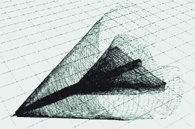
Visualization of the shock waves system emanating from the body tip and the wing is shown in Figure 65. A new visualization technique (125j allows for analyzing shock waves found by CFD analysis in 3D space: their quality near the aircraft, as shown, or with refined CFD analysis in larger distances to investigate sonic boom propagation, may be a useful help to assess this environmentally important aspect of supersonic transport. The figure shows a cut-off domain of the shock surfaces: A shock strength threshold allows analysis of local sonic boom quantities.
|
Figure 65 Visualization of CFD results: Shock system emanating from body tip and wing root, cut-off at threshold for selected sonk boom strength. |
Case studies for new generation supersonic transport aircraft have been carried out through the past years in research institutions and in the aircraft industry. Our present tool to shape such configurations needs to be tested by trying to model the basic features of various investigated geometries. Knowing that the fine-tuning of aerodynamic performance must be done by careful selection of wing sections, wing twist distribution and the use of scaled slats and flaps, with initial exercises we try to geometrically model some of the published configurations, generate CFD grids around them and use optimization strategies to determine the sensitivity of suitable geometry parameters. This is still a difficult task but tackling its solution greatly contributes to building up the knowledge base of high speed design.
9.4.1 Example: Generic High Speed Civil Transport Configuration
Figure 62 and Figure 63 illustrate data visualization of a generated configuration derived from a Boeing HSCT design case for Mach 2.4 (123J. The configuration consists of 10 components, engine pylons arc not yet included. Wing and horizontal and vertical tail components are spanwise defined, fuselage and engines are axially defined components. The wing has a subsonic leading edge in the inner portion and a supersonic leading edge on the outer portion.
|
|
|

^ГПТ-ЦЦ
Figure 63 Generic HSiT configuration: Three-view wireframe model
For this study a minimum of support airfoils (Figure 58) is used to get a reasonable pressure distribution: a rounded leading edge section in most of the inner wing and a wedge-sharp section in the outer wing portion define the basic shape of the wing. Wing root fillet blending, the smooth transition between rounded and sharp leading edge and the tip geometry are effectively shaped by the previously illustrated wing keys, the fuselage here is a simple slender body requiring just the baseline body tool with elliptical cross sections.
Preprocessing input data for CFD requires providing a gnd surrounding the configuration. For application of cither structured or unstructured grids additional geometric shapes need to be provided. In the case of the generic HSCT with given supersonic flight Mach number the farficld boundary is chosen to engulf the expected bow shock wave (Figure 64a) and a cross sectional grid for both wing and body is generated, cither as simple algebraic trajectories or using elliptic equations.
|
Figure 64 CFD grid boundaries, result for Euler analysis of HSCT wing-body in supersonic flow MM = 2.4 |
Short runs using an the inviscid flow Euler option of a flow solver [I24]wcrc carried out on a coarse (33 x 81 x 330) grid, here only to get an idea about the needed wing section and iwist modifications for acceptable pressure distributions. Visualization of the results in various gnd surfaces is needed, like pressure distributions in cross section planes as shown in Figure 64b.