Category Principles of Helicopter Aerodynamics Second Edition

Indicial Pitching Moment from Angle of Attack

A similar process to that described previously can be used to find approximations for the other indicial response functions. The indicial pitching moment response about the 1 /4-chord resulting from a step change in angle of attack, a, can also be written as the sum of a noncirculatory part, , and a circulatory part, Ccma, that is,

Cma(s) = C£(s, M) + Ccma(s, M) (8.154)

or in terms of the indicial functions

+ у (°-25 – M) (8.155)

For the noncirculatory part, a convenient general expression for the indicial function is of the form

CM = Азехр + A4exp(^Oj. (8.156)

One approximation to this function uses the values A3 = 1.5, A4 = —0.5, Ьз = 0.25, and = 0.1. Following a similar approach to that used above for the lift, but now using Eq. 8.155, gives the noncirculatory time constant as

г“-=Шт«-=

Indicial Pitching Moment from Angle of Attack

Distance traveled by airfoil in semi-chords, s

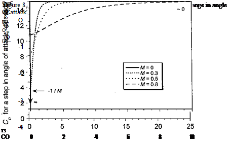
Thus, the noncirculatory time constants Ta, TUm, Tq, and Tqm used in the indicial response functions are now defined in terms of the other (circulatory) coefficients. These functions are only weakly dependent on Mach number in the low subsonic flow regime; however, their values increase rapidly as M = 1 is approached but the theory breaks down here anyway.

The four basic indicial functions are plotted in Figs. 8.30 and 8.31 for several Mach numbers to illustrate their behavior. The considerable influence of Mach number com­pared to the incompressible values should be noted. In application, these subsonic indicial aerodynamic functions are manipulated in exactly the same way as that shown previously for the incompressible case when using the exponential approximation to the Wagner or Kussner functions. For example, in the case of the subsonic lift to an arbitrary variation in a, three recurrence equations or three states instead of two must now be used, with both the circulatory and the noncirculatory terms having a time-history effect.

Determination of Indicial Function Coefficients

The coefficients A, A2, b, and bj are used to define the intermediate behavior of the indicial lift approximations. Using experimental results for the total lift and pitching moment response resulting from a prescribed harmonic forcing, such as oscillations in pitch or plunge, we can relate these data back to empirically determine the coefficients of the indicial functions. Experimental data are available from a number of sources. For the most part, they comprise measurements of the unsteady aerodynamic lift and pitching moment as a function of reduced frequency from pitch and plunge oscillations performed under nominally attached flow conditions; that is, in the region where linearized aerodynamics are appropriate. It is essential that the data selected be for attached flow conditions as the presence of nonlinearities that arise from flow separation effects introduces further complications in the validation of the indicial responses. In Beddoes (1984) and Leishman (1993), data were taken mainly from the results of Liiva et al. (1968), Wood (1979), and Davis & Malcolm (1980).

Because the indicial functions have been completely defined as exponential functions of time, they may be easily manipulated using Laplace transforms. If we consider just the

Подпись: Cca(p) = СПа(М) Подпись: 1 P Подпись: AiTi 1 + TlP Подпись: A2T2 1 + т2р Подпись: (8.142)

circulatory part of the lift from AoA given by Eqs. 8.131 and 8.134, the Laplace transform of this part of the indicial response function yields

2Vbf2 2 Vb2f2

The Laplace trar

of attack) is given by a(p) = 1/p. The circulatory lift transfer function can be simplified to

A A2

Determination of Indicial Function Coefficients

where

Determination of Indicial Function Coefficients Подпись: A A2 1 A Tp 1 + T2p Подпись: (8.144)

Because the initial value of the circulatory indicial response is zero (i. e., фс{0, M) = 0), then (1-А! — A2) = 0 and the lift transfer function simplifies further to

For the noncirculatory lift from angle of attack, the Laplace transform of the indicial response yields the transfer function

Подпись:C"c(P) _ 4 / 7> a(p) M 1 + Цр

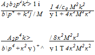
Ab2p4 A2b2p4 4 / 4ic2M2k2 ‘

bf4 + k2 + blP4 + k2) + M +4к2М2к2

‘ Афф2к A2b2p2k 4 / 2KaMk

b2p4 + k2 + bp4 + k2) + M Vl+4KaM2k2

/ AbP2k2 ( Afi4k

Determination of Indicial Function Coefficients Подпись: A2b2p2k2> 1 і 1 4/cq M2k2 bp4 + k2j / M у 1 + 4к2М2к2 A2p4k > )+^ / 8к2М2к3 bp4 + к2 у у 1 Т 4к2М2к2 Determination of Indicial Function Coefficients

and the transfer functions for the other lift components can be derived in a similar way. Therefore, for any forcing function for which a Laplace transform may be easily derived (such as for a sinusoid), the lift and pitching moment response may be derived in explicit form by using inverse Laplace transforms in terms of the assumed form of the indicial response function (see also Questions 8.4-8.7). For example, the lift response to a harmonic pitch oscillation with a reduced frequency к about the 1 /4-chord axis of the airfoil may be obtained after some algebra as

where [Я and S3 denote the real and imaginary parts of the aerodynamic response, respectively. The resultant frequency response can be obtained by summing the various contributions to the real and imaginary components. A similar approach can be adopted to find the response

Table 8.2. Coefficients of Indicial Lift Approximation Deduced from Oscillating Airfoil Experiments

Data Source

A,

Аг

by

b2

«5.

Sq

Boeing Data

0.636

0.364

0.339

0.249

0.77

0.70

ARA Data

0.625

0.375

0.310

0.312

1.00

1.00

NASA Data

0.482

0.518

0.684

0.235

0.72

0.70

All Data

0.918

0.082

0.366

0.102

0.85

0.73

from harmonic plunge oscillations, which of course, are useful because they do not include any pitch rate (q) terms in the aerodynamic response.

A vector x can now be defined that consists of the coefficients At, A2, by, and b2 used in the indicial lift function:

xr = (A, A2;b, Ьг-, &„,&„)■ (8.150)

The additional factors 8a and 8q are empirical values chosen to modify the initial value of the indicial response functions to account for the possibilities of 3-D or finite-span effects present in the airfoil measurements. It has been shown, however, that their values are al­ways close to unity, suggesting that the unsteady airfoil measurements selected are indeed representative of 2-D unsteady flow. The vector in Eq. 8.150 must be chosen to minimize the difference between the explicit solution based on the assumed indicial response approx­imations and the reference solutions (in this case, experimental results) for the unsteady lift in the frequency domain. If the real and imaginary parts, Fm(M, ) and Gm(A/, ), respectively, are known at up to M values of reduced frequency and at each of I values of Mach number, an objective function J(x) can be defined as

/

J = ]Tj(x, Mi), (8.151)

/=i

where

M

J(x, Mi) = [Fm(Mi) – ЯС„(х, Mi, km)]2 + [Gm(Mi) – 3C„(x, Mt, km)f .

m= 1

(8.152)

The minimum of the objective function J in the parameter space x will give the best ap­proximation to the known (reference) lift transfer function. Therefore, the objective function minimization algorithm is basically a nonlinear programming problem of minimizing J(x) subject to the constraints

2

An, bn > 0, n = 1,2 and 0 < 8a, 8q < 1 and An = 1. (8.153)

n=l

The latter equality constraint may be replaced by a penalty function. Notice that although Table 8.2 shows that the different sets of experimental data result in slightly different values of the coefficients A, A2, by, and &2, the differences are of limited practical significance; the quality of the derived indicial functions is as good as the quality of the experimental data.

Indicial Lift from Pitch Rate

The indicial lift response to a step change in pitch rate q about the 1/4-chord can also be written as the sum of a noncirculatory part, C"^ and a circulatory part, , that is

C„,(s) = C^(s, M) + Ccat(s, M) (8.137)

Подпись: Cn,(s) q Indicial Lift from Pitch Rate Подпись: (8.138)

or in terms of the indicial functions

Numerous references have shown that, for incompressible flow, the chordwise pressure variation on the airfoil is the same as the thin-airfoil loading but is independent of the mode of motion. Therefore, an angular velocity about some point can be considered equivalent to an angular velocity about some other point plus an angle of attack. In particular, the indicial lift for a pitch rate about the 3/4-chord position in incompressible flow is an impulse at s = 0

onH ic 7prn tbf*TV*Q-ftpr $2nVic**mu»nt1 v it finllnwc that frvr inr>nrrmrpccibl<a flnw = rhc

Шіиш V/1UVI.1; ^4^ , 111V/I1VITU X* w »» —- ysq.

Подпись: 7Г 1 Indicial Lift from Pitch Rate Подпись: (8.139)
Indicial Lift from Pitch Rate

In linearized subsonic flow, the circulatory lift lag still remains an intrinsic function of the fluid itself. The chordwise pressure variation remains the same as the steady thin-airfoil loading and is unaffected by the mode of forcing or pitch axis location. Therefore, on a thin airfoil in subsonic flow, the lift always acts at the 1 /4-chord point. In view of the foregoing, it is valid to assume 4>ca{s, M) — <pcq{s, M) for subsonic compressible flow as well as incompressible flow without any loss of rigor. The circulatory part of the lift from pitch rate about the 1 /4-chord, therefore, can be written as

The noncirculatory function can be assumed to be of the form

= = p^). (8.140)

Using Eqs. 8.139 and 8.140 and following the same procedure as before where the slopes of the approximating indicial function and the exact result (in this case, Eq. 8.120) are matched at j = 0 gives the time constant as

T, = = [(1 – М) + 2жрмАф1 + ЛЛ>Ґ “ = K*T‘- <8Л41>

Indicial Lift from Angle of Attack

The lift or normal force response to a unit step change in angle of attack, a, can be idealized as the sum of a decaying noncirculatory part, C”c, and a growing circulatory part, СсПа, that is

Cn.(s) = C£(s, M) + Ccna{s, M) (8.130)

or in terms of the indicial functions

C„„(s) – ~<f>a(s, M) + у #(*, M). (8.131)

Using reciprocal relations, the noncirculatory component of the loading on the airfoil can be theoretically extracted from the total lift response. This was first done by Mazelsky (1952a). The result can be closely approximated as an exponentially decaying function, and so the noncirculatory part of lift for a unit step change in a may be written as –

C£(S, M) = m = L exp, (8.132)

where T’a = T^(M) > 0 is a Mach number dependent time-constant still to be defined. For the growing (circulatory) part of the total indicial response, Mazelsky (1952a, b) appears to have been one of the first investigators to use an exponential approximation of the form

N N

0cCs, M) = 1 — J2 Ane~bnS-, J2 A“ = 1, bn > 0 (8.133)

n—1 И=1

for compressible flow, where the coefficients An and bn will vary as a function of Mach number. These coefficients were obtained indirectly by Mazelsky by relating back into the time domain from numerical results (transfer functions) obtained for oscillating airfoils in the frequency domain. A similar approach has also been suggested by Dowell (1980) to obtain approximations to the indicial response for incompressible flow using Theodorsen’s exact result and for compressible flows by using transfer functions numerically computed using CFD solutions to the unsteady flow problem. In general, indicial type CFD calculations are rare in the published literature, but direct indicial and vertical sharp-edged gust solutions have been performed by McCroskey & Goorjian (1983) using CFD methods. A series of more elaborate direct indicial calculations have been performed by Parameswaran & Baeder (1997) who have computed indicial angle of attack, pitch rate and sharp-edged gust results using an Euler/Navier-Stokes CFD method. These solutions provide good check cases for unsteady airfoil problems that cannot be simulated by experimentation nor amenable to exact analytical treatment. However, these CFD solutions are only available at a relatively high computational cost, and even then they are still subject to certain approximations and limitations.

While Mazelsky’s exponential approximation in Eq. 8.133 may be acceptable for appli­cations in fixed-wing analyses, it is not entirely convenient for a helicopter rotor analysis. This is because each blade station encounters a different local Mach number as a function of both blade radial location and azimuth angle. Therefore, repeated interpolation of the An and bn coefficients will be required between successive Mach numbers to find the locally effective indicial function. Although relatively simple in concept, there is relatively large computational overhead associated with this process. In addition, it must be recognized that when superposition is applied to find the unsteady lift, each exponential term in the series in Eq. 8.186 contributes an additional state or deficiency function. To this end, Beddoes
(1984) and Leishman (1987a, 1993) have assumed that the circulatory lift can be expressed in terms of a two term growing exponential function, but one that scales directly with Mach number alone. The lift function fca(s, M) takes the general form

<pca(s, M) = 1 – Ae~b’p2s – A2e-b2^s A+ A2 = 1, Ъъ b2 > 0, (8.134)

where /3 = Vl — M2, and the A and b coefficients are fixed and independent of Mach number.[35] The use of the fi2 term in the indicial function reflects the effects of compressibility (Mach number) on the growth of the circulatory part of the lift (through the effects of the shed

Подпись:Подпись:lags in the growth of lift at higher Mach numbers. Such a behavior is well known from a theoretical standpoint [see Osborne (1973)] as well as from experimental observations with oscillating airfoils. Furthermore, in a practical sense, not only is this simple compressibility scaling approach a computationally efficient way of accounting for compressibility effects in the wake, but it is also more accurate than repeated linear interpolation of the coefficients between discrete Mach numbers.

The coefficients A, A2, b, and b2 must be assumed as initially unknown, and although they could be derived in a number of ways, they can be reliably determined by relating back from frequency domain results using experimental measurements for oscillating airfoils in subsonic flow. Such measurements are widely available; see, for example, Liiva et al. (1968), Wood (1979), and Davis & Malcolm (1980). It is possible to reduce the number of coefficients implicit in the indicial representation in Eq. 8.131 from five to four by obtaining an expression for the noncirculatory time constant, in terms of the coefficients A, A2,b,

and b2. Differentiating the approximation in Eq. 8.131 (using Eqs. 8.132 and 8.134) and the exact result in Eq. 8.118, and equating the gradients at s = 0 gives the time constant in the s domain as

T'{M) =————————————————- . (8.135)

“ 2(1 — M) + 2nfM2{Ab + A2b2)

Using the results Ta = (c/2V)T^ and M = V/a gives the time constant in the t domain as

Ta = [ (1 – M) + лрмАфі + A2b2)Y C~ = KaTit (8.136)

where 7} = с/a. The advantage of taking this approach is that, regardless of the values of the coefficients Ai, A2t bi, and b2, the noncirculatory constant, Ta, will always be adjusted give the correct initial value and slope of the total indicial response as given by exact linear theory in Eq. 8.118. The continuity between the initial impulsive and succeeding circulatory loading is then obtained using linear superposition, as given by Eq. 8.131.

Approximations to the Indicial Response

The exact results given in Eqs. 8.118-8.121 are only valid for short values of time but they are useful because they provide guidance in developing approximations for the indicial functions for all values of time that are also in a more convenient analytic form to derive recurrence solutions to the Duhamel integral or for state-space realizations (see previously). In the general case, the indicial normal force and 1/4-chord pitching moment response to a step change in angle of attack, a, and a step change in nondimensional pitch
rate about the 1 /4-chord, q (= ас/ V), can be represented by the equations

Подпись: C„>) a Cnrjs) a Cnq(s) Я Cmq(s) Я M) + M), (8.122)

M) + у #(*. M) (0.25 – xac), (8.123)

^c(s, M) + j4><(s, M), (8.124)

(8’125)

where фпс refers to the assumed noncirculatory part of the indicial response and фс refers to the assumed circulatory part. While it must be remembered that in the subsonic case this decomposition of the total loading is only an idealization, it is convenient for engineering purposes to handle the problem this way. The (5 term is the Glauert compressibility factor for linearized subsonic flow (i. e., /6 = y/ — M2). In the preceding equations, the initial values of the indicial response functions are given directly by linear piston theory as

CnA*= o) a

4

M

and

Cmo(j=0) 1 a M ’

(8.126)

Cnq{s = 0)

1

and

О

s

Co

II

о

1

1

-j

(8.127)

Я

M

q 12 M’

The final values are given by

the steady linearized subsonic theory as

C„a(s = oo) a

2tt

= T

and

Cma(s = oo) _ 2тг /n Л — o (0-25 -*чїс) ) a p

(8.128)

Cftq (A ~ OO)

and

Cmq{s = OO) ЛГ

(8.129)

Я

" P

Я ~ 8/Г

It should be noted that in practical applications the linearized value of the lift-curve-slope, 2n/f, can be replaced by the measured value for a given airfoil at the appropriate Reynolds number and Mach number,[34] which is generally denoted by СПа (M). Additionally, the second term in Eq. 8.123 represents the contribution to the pitching moment resulting from a Mach number dependent offset of the aerodynamic center from the 1 /4-chord axis of the airfoil, an effect previously described for the incompressible flow case. As shown in Section 7.7.1, the values of the aerodynamic center, xac, for a given airfoil can be obtained from static airfoil measurements at the appropriate Mach number. Also notice that the second term of Eq. 8.125 represents the induced camber pitching moment resulting from the pitch rate motion, as given by the quasi-steady thin-airfoil result, as also previously described. Therefore, it will be appreciated that the various indicial response functions, denoted by ф, represent the time-dependent behavior of the lift and pitching moment between the initial “piston theory” values at s = 0 and the normal quasi-steady values at s = oo.

Indicial Method for Subsonic Compressible Flow

All rotor aerodynamic problems involve compressibility to some degree. However, for subsonic compressible flow there is no analytic equivalent to Theodorsen’s theory, nor to the Wagner or Kiissner functions. This is because of the nature of the governing equation, which for the subsonic case is the hyperbolic wave equation versus the elliptic Laplace’s equation for incompressible flow [see Karamacheti (1966) and Chapter 14]. Therefore, alternative numerical means of finding the indicial responses must be derived. Because a time domain representation of the unsteady aerodynamics is sought, it is convenient to address the subsonic problem starting from the indicial response. Although this is by no means the only basis from which the problem can be tackled, it has already been shown that the indicial approach gives considerable physical insight into the problem of unsteady aerodynamics.

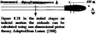
For a compressible flow, the initial loading on the airfoil after an indicial (step) input comprises a pressure wave system with a compression wave on one surface of the airfoil and an expansion wave on the other. This initial pressure loading on the surface can be computed directly using linear piston theory, which is a local wave equation solution for the unsteady airloads [see Lomax (1968)]. The piston theory gives a result valid for any Mach number, M, but only at the instant after the perturbation has been applied (i. e., at t = 0 or s — 0). If we consider a small element of an airfoil subject to a downward plunging type motion that produces a change in normal velocity Aw as shown in Fig. 8.28, then piston

Подпись:Подпись: (8.114)theoi у gives the difference in pressure across the surface as Ap = 2,pa A. w, so

2paAw(x) f 4 ^ Aw(x)

= Pv2 = J V

Indicial Method for Subsonic Compressible Flow Подпись: V

Consider now a thin-airfoil undergoing a simultaneous plunging and pitching about the 1/4-chord. Figure 8.5 has shown that the normal velocity on the airfoil is composed of two primary modes: a uniform perturbation in w from the pure AoA contribution plus another uniform perturbation resulting from plunge velocity, h/V, and another perturbation mode

from the pure pitch rate of the airfoil q (= ac/V). By convention it will be assumed that the pitching motion takes place about the 1 /4-chord, although the result can be generalized to any pitch axis. For a step change in each mode, applying piston theory and integrating across the chord gives the normal force coefficients[33] at t = 0 as

ДСИа(0)= ^Act and ACnq(0)=^Aq (8.115)

and the initial moment coefficients about the 1 /4-chord as 1 7

AcmeW=- —Да ana ACm,(0) = —(8.116)

For subsequent time, pressure waves from the airfoil propagate at the local speed of sound and, in the absence of any other forcing, the loading will decay rapidly with time from these initial “noncirculatory” values. For a compressible flow the noncirculatory terms do not appear as an infinite pulse at s = 0 as for incompressible flow, but are finite in magnitude and decay more slowly from their initial values. Therefore, it will be appreciated that noncirculatory terms can no longer be assumed proportional to the instantaneous blade motion (i. e., to a, a, h) as they are for the incompressible case and, like the circulatory terms, they must also depend on the time history of the forcing. Physically this is because for an incompressible flow the pressure waves are propagated at infinite velocity, whereas for a real flow the disturbances propagate at the speed of sound.

Indicial Method for Subsonic Compressible Flow Indicial Method for Subsonic Compressible Flow

Such a transient behavior is difficult to compute in subsonic flow, but some analytic solutions can be obtained for limited values of time after the step input has been applied. Using an analogy of unsteady 2-D subsonic flow with steady supersonic flow, solutions to the wave equation have been evaluated exactly by Lomax et al. (1952) to obtain the chordwise pressure loading on the airfoil in the short period in the range between 0 < s < 2M/(M+1). For a unit step change in AoA then

where the domain is x’ = x — Mt. This equation is valid for the early period 0 < t < c/(l + M). The symbol 9t refers to the real part where the real parts of the arc cosine of numbers greater than 1 and less than 1 are 0 and 7Г, respectively. Results are shown in Fig. 8.29 for M = 0.5. Notice the nature of the chordwise pressure loading as the upstream and downstream moving waves pass over the chord of the airfoil. Even after a very short time, the growth in circulation has been established, but the final value steady state circulation is only obtained after a relatively long time. Stahara & Spreiter (1976) and Singh & Baeder (1997a) show numerical solutions to the same problem using CFD methods.

By integrating the exact chordwise pressure loading solution in Eq. 8.117, the lift (normal force) and pitching moment during the short period 0 < s < 2M/(1+M)canbedetermined analytically. The lift coefficient resulting from a step change in AoA is

Подпись: (8.118)Cna(s) 4 Г 1-М

——– = —– 1————— 5

a M 2M

State-Space Solution for Arbitrary Motion

For some applications, it is more convenient if the unsteady aerodynamic model is written in the form of differential equations (i. e., in state-space or state-variable form). The differential equations describing the unsteady aerodynamics can then be directly appended to the structural dynamic equations governing the airfoil or blade motion. One advantage of this approach is that the stability of an aeroelastic problem for a wing section or rotor blade can then be obtained by formulating it as an eigenvalue problem or using a Floquet stability analysis [see Johnson (1980)]. Alternatively, the problems can be studied by time integration of the governing equations using standard numerical algorithms.

One of the most fundamental concepts associated with the description of any dynamic system, aerodynamic or otherwise, is the state of the system. The state describes the internal behavior of that system and is simply the information required at a given instant in time to allow the determination of the outputs from the system given future inputs. In other words, the state of the system determines its present condition; it is represented by a set of appropriately chosen variables describing the internal mechanics of the system. These variables are called the state variables and define an n -dimensional vector space x called the state-space in which one coordinate is defined by each of the state variables x, x2, xn. A general nth order differential system with m inputs and p outputs may be represented by n first-order differential equations

x = Ax + Bu (8.100)

with the output equations

у = Cx + Du, (8.101)

where x = dx/dt u = и;,’ і = 1, 2, …, m are the system inputs, and the у = yt, і = 1, 2,…, p are the system outputs, x = Хі, і = 1, 2,…, n are the states of the system. See Franklin et al. (1994) for more information about this approach.

The state equations describing the behavior of a 2-D unsteady airfoil can be obtained through direct application of Laplace transform methods to the indicial response. Consider the indicial lift response, ф, which is to be approximated by the exponential function given previously by Eq. 8.76. This function can be written in the time domain as

0(0 = 1.0 – Axe~b^> – A2e~b2(^>. (8.102)

State-Space Solution for Arbitrary Motion State-Space Solution for Arbitrary Motion

Initially, let 0(0) = 0 = 1 — Ai — A2. Then the corresponding impulse response, h(t), is given by

From this transfer function, the lift response to an input a(t) can be directly written in state-space form as

Подпись: a(t),State-Space Solution for Arbitrary Motion(8.106)

State-Space Solution for Arbitrary Motion

and the output equation for the lift coefficient is

State-Space Solution for Arbitrary Motion(8.108)

and the corresponding equation for the lift coefficient is

Подпись: (8.109)cm = cla[bxb2 (^)2 (Ab + A2b2) (f )]{XX }.

For a nonzero initial condition, such as when using the Wagner function approximation, the form of these equations is only slightly different. In this case

State-Space Solution for Arbitrary Motion(8.110)

id the equation for the lift coefficient is

Ci(t) — Cta |A] + A2)bb2 (^) (Ab + A2b2) (^) ] I I

Подпись: (8.111)+ C/o(l — A — A2) ot(t).

Подпись: with
State-Space Solution for Arbitrary Motion

For example, if R. T. Jones’s approximation to the Wagner function is used (Eq. 8.51), then after substituting the numerical values of the coefficients we get

where Cia = 2tt. The extra term 7ra/2 on the right-hand side of the above equation arises be-

Подпись: cause of the non-zero initial conditions for the Wagner function, that is, 0(0) = 1—A1 — A2

1 /2. Conversely, if we apply a unit step input to the above state-space equations and set the initial states to be zero [i. e., a(t) = 1 for t > 0 and xi(0) = *2(0) = 0], the resulting response is exactly Jones’s approximation to the Wagner function (see Question 8.11). In fact, it is clear that the Theodorsen solution, the Wagner solution with Duhamel super­position, and the above state-space model are simply different mathematical realizations of the same aerodynamic system. Friedmann (1985), Dinyavari & Friedmann (1986), and Leishman & Nguyen (1990) describe state-space unsteady aerodynamic models of 2-D airfoil sections using Jones’s approximation to the Wagner function for the incompressible flow case. Friedmann (1985) describes a more general, but still approximate, state-space

realization of Loewy’s function (Section 8.8). This is done by representing Loewy’s exact lift transfer function as a higher-order Pade approximation – see also Vepa (1976).

Recurrence Solution to the Duhamel Integral

Подпись: -bS Подпись: A . „~blS Подпись: (R

If a general two term exponentially growing indicial function is assumed such that

then the Duhamel integral in Eq. 8.74 can be written numerically as

Подпись: — {o)(f)(s — a)do dsae(s) = a(s0)(/>(s) + /

j So

= a(i0)(l – Ate~b’s – Aie-b*)

+ / — (<7)(1 – – A2e-b^s-a))da

Jso ds

= a(s0) – Аісф0)е b’s ~ A2a(so)e blS + f da(s)

Recurrence Solution to the Duhamel Integral Подпись: (8.77)

Jso

Notice that the terms Aa(so)e~b’s and A2a(so)e~b2S containing the initial value of a are short-term transients and can be neglected. Therefore, the Duhamel integral can be rewritten

as

Подпись: (8.78)cte{s) = a{s) – X(s) – Y(s),

7 Notice that the result in Eq. 8.74 can also be extended to finite wings, where ф represents the indicial aerodynamic response of the entire wing as opposed to a single 2-D section – see Jones (1940) and Lomax (1968).

which is in the notation used by Beddoes (1976, 1984), where the X and Y terms are given by

X(s) = A f o)e-bl{s~a)do, (8.79)

Ло ds

Y(s) = Л2 [ ^(o)e~b2{s-a)do. (8.80)

Ло ds

Assuming a continuously sampled system with time step As (which may be nonuniform) and that so = 0, then we have at the next time step s + As

Подпись:ps+As j

X(s + As) = A / —(o)e~b^s+As~a)do.

Jo ds

Splitting the integral into two parts gives

ps Ary ps~-As Ary

X(s + As) = Axe~b’As / ~—{o)e-bds-^da + A / —(o)e~b'{s+As-a)do Jo ds Js ds

(8.82)

= X(s)e~biAs + Ai / -~(o)e~b'{s+As-a)da

Js ds

Подпись: (8.83)= X(s)e~b’As + /.

Notice that this new value, X(s+As), is a one-step recursive formula in terms of the previous value, X(s), and a new increment, /, over the new period. Consider now the evaluation of the I term:

fS + AS J fS+AS J

I = Ax —(a)e-b'(s+As-a)da = Axe-b’is+As) / -~{о)еь’аdo

Js Js

= Aie-b^s+As) / —{o)f{o)do (8.84)

Recurrence Solution to the Duhamel Integral Подпись: a(s + As) — a(s) As Подпись: As Подпись: (8.85)

with f(o) = eb’a. At this point, several simplifying assumptions can be made. Introducing a simple backward-difference approximation for da/ds at time 5 + As gives

Recurrence Solution to the Duhamel Integral Подпись: 3a(5 + As) — 4a(s) + a(s — As) 2 As Подпись: (8.86)

which has an error of order a"(s 4- As)As. Alternatively, we could use

which has an error of order a"'{s + As)(As)2, although this scheme requires the storage of a at two previous time steps. The remaining part of the integral involving /(cr) can be evaluated exactly and / becomes

Recurrence Solution to the Duhamel Integral(8.87)

Подпись: 1 _ e-b,As b Подпись: As. Подпись: (8.88)

when using Eq. 8.85. Now, if b As is small so that b2(As)2 and higher powers can be neglected, then

Подпись: I = A Подпись: A&S+AS As Подпись: As — Лі Да5+д^. Подпись: (8.89)

Therefore, we obtain the relatively simple result that

It will be seen that this latter result is equivalent to setting f(o) — constant = ebl(-s+As^ over the sample period (i. e., using the rectangle rule of integration) and has a local error of order (As)2. When Eq. 8.89 is introduced into Eq. 8.83, this gives the recurrence formula

X(s + As) = X(s)e~bl As + A, Aas+Aj (8.90)

or

X(s) = X(s – As)e~b, As + A, Aas. (8.91)

Proceeding in a similar fashion for the Y term in Eq. 8.80 gives

ae(s) = a(0) + f da(s) – X(s) – Y(s) = a(s) – X(s) – F(s), (8.92)

Jo

where the X(s) and Y(s) terms are given by the one-step recursive formulas that will be denoted by Algorithm D-l:

Подпись: (8.93) (8.94) X(s) = X(s – As)e~’biatS + Ai Да, Y(s) = Y(s – As)e~b*As + А2Да,

Recurrence Solution to the Duhamel Integral Подпись: b2As 1 _ (,-b-iAs Подпись: (8.95)

Notice that recursive functions X and Y contain all the time history information of the unsteady aerodynamics and are simply updated once at each time step, thereby providing numerically efficient solutions to the unsteady lift for arbitrary variations in a. Obviously, the above results can be extended to other modes of forcing and to any number of exponential terms that may be used to represent the indicial function. The error in this algorithm results mostly from the approximation used in Eq. 8.88, and it can be shown that the relative error in the integral is

Generally, to obtain errors of less than 5%, each of the products b As and b2As must be less than 0.05. This тр/іііігр. к я rglabvelv «mall time sten and mav not alwavs be oractical in many helicopter rotor problems.

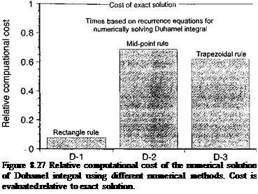
The main reason for adopting an algorithm of this latter form is that there is a significant computational overhead associated with the repetitive numerical evaluation of the formula for I containing the exponential function in Eq. 8.87 versus using the simpler result that / = A AQff+дг; the relative computational cost is a savings of about one order of magnitude (see Fig. 8.27) over using the exact solution. Bearing in mind these algorithms are intended for use in various helicopter rotor analyses where the recurrence formulas may be evaluated tens or hundreds of thousands of times, an order of magnitude extra overhead just to get an exact solution is certainly significant. However, this is at the expense of notable errors

Algorithm number

Подпись: Figure 8.27 Relative computational cost of the numerical solution of Duhamel integral using different numerical methods. Cost is evaluated relative to exact solution.

for practical values of the sampling time step, and the motivation for developing alternative algorithms that are still numerically efficient but have lower numerical errors becomes clear.

If As (or the products bAs or b2As) is large, another approximation based on the midpoint rule can be used. In this case let f(a) « f(s + As/2), and thus

/ = л, е-^+45> fWo

— Axe~bx{s+As) ( A(Xs+As ^ ebx{s+As/2) As As )

= AlAas+Ase~bxAs/2. (8.96)

This gives a method that will be denoted as Algorithm D-2:

ВД = X(s – Дs)e~bxAs + Ai До* e~bxAs/2, (8.97)

Y(s) = Y(s – As)e~blAs + A2Aas e~blAsl2. (8.98)

Подпись: € = 2 Recurrence Solution to the Duhamel Integral Подпись: (8.99)

This recurrence algorithm was first used by Beddoes (1984). This method has a local error of order (As)3, and the relative error in the integral can be shown to be

In this case, Eq. 8.99 suggests that errors of less than 1% from an exact solution will be obtained if both b As and b2As are less than 0.25, which is a much more practically realizable option in a helicopter rotor analysis, despite a notable increase in computational cost. It is, however, still less expensive than the exact solution. See Question 8.8 for a solution to this numerical problem using the trapezoidal rule (Algorithm D-3).
General Application of the Indicial Response Method

As described previously, if the indicial aerodynamic response(s) can be determined, then these solutions form a powerful means of finding the unsteady aerodynamic forces and pitching moments in the time domain in response to arbitrary variations in AoA and/or in­flow velocity by using Duhamel superposition. The effects of a time-varying incident flow
velocity may also be handled by means of this approach. There are two main difficulties with this method, however. The first is to determine the indicial response functions themselves. While they are known exactly for incompressible flow (e. g., Wagner and Kiissner func­tions), they are not known exactly for subsonic compressible flow. Nevertheless, there are various techniques that can be used to find and approximate forms of the indicial response from aerodynamic transfer functions obtained from experimental measurements. Second, numerical methods must be devised to enable the superposition process to be conducted accurately and computationally efficiently.

General Application of the Indicial Response Method Подпись: (8.70)

The indicial method is based on the fundamental principle that the flow can be linearized with respect to the forcing function. For example, a generalized unsteady force coefficient acting on the airfoil, say Cf(t), can be assumed to be a smooth, nonlinear function of angle of attack, a. About some mean value of angle of attack, say am, this allows C/ to be expressed as the first-order Taylor series expansion

This approximation will become more exact as the step Да -» 0. If С/ is a linear function of a, then Eq. 8.70 is already exact. If dCf/da is a linear time invariant response such that it does not depend on a and so depends only on the time after the step input is applied, then the linear result for С/ is

Cf(t) = Cf{t = 0) + ^-(t)Aa = Cf(t = 0) + 0/(0 Да, (8.71)

where 0/(0 is called the Umar indicial response of C/, in this case to a step input in a.

For arbitrary inputs in a, then as shown previously the value of С/ can then be expressed in terms of the Duhamel superposition (or convolution) integral as

dC f dC f da

Cf{t) = -^a(O)0y(O +-^-Jo ~ (8-72)

where the first term is a short time transient. The evaluation of the Duhamel integral, there­fore, produces an aerodynamic quantity that contains all of the prior time-history information of what has happened to the aerodynamic response since the initial time. Equation 8.72 is solved numerically (see Section 8.14.1) and different approaches can be formulated. Notice that in the limit of steady flow, Eq. 8.72 reduces to the trivial result that

Подпись: Cf =Подпись: a = constant,General Application of the Indicial Response Method(8.73)

which is fully consistent with linearized, steady airfoil theory.

General Application of the Indicial Response Method Подпись: = Qaae(t), Подпись: (8.74)

The time-varying value of the lift coefficient, Q(t), can be expressed as a function of angle of attack, a(t), in terms of the Duhamel integral as

where 0(5) is indicial response to a unit step input a and Qa is the lift-curve-slope (= 27r/radian for incompressible flow). If the integral is evaluated, then the term ae(t) can be
viewed as an effective AoA in that it contains all the time history information.7 Equation 8.74 is usually solved numerically for discrete values of time. For a discretely sampled system at times s = s, ai, …. ,ct2,g, s, then ae(s) can be written using Eq. 8.74 as

^da

ae(s) = a(s0)cp(s) + 2_j — (о’іЖ’*’ – о^Да,-

(=i

= сфоЖ^) + ot'(a)4>(s – <7і)Д(7і + a'(a2)f(s – a2)Aa2 H——

4- a/(crl)0(5 – сг^Дсг,- H—– , (8.75)

with the summation extending over all inputs that have acted up to the instant 5. Therefore, the result for ae(s) requires the storage of a’Cs), afcrj),…, a'(oi) at all previous time steps and the repeated reevaluation of the indicial function for each 5 — cr, at each new time step. Obviously, in most cases information at a large number of previous time steps must be retained. Also, the indicial response function is not always known in a convenient simple analytic form, such as with the Wagner and Ktissner functions, so a relatively large number of numerical operations must be performed. This is not helpful for a helicopter rotor calculation, but, fortunately, there are alternative approaches to solving this numerical problem.

Time-Varying Incident Velocity

The previously described unsteady airfoil solutions have considered the local free stream velocity to be constant. However, in forward flight a typical blade element on a rotor

Time-Varying Incident Velocity

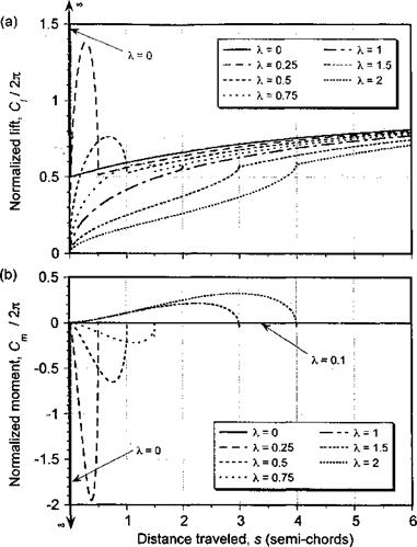
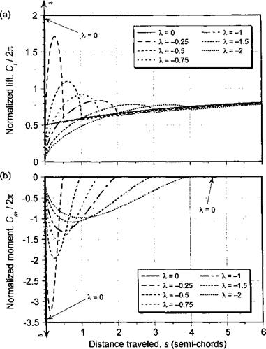
Figure 8.23 Airloads produced for a series of downstream moving sharp-edged vertical gusts, (a) Lift, (b) Pitching moment about 1 /4-chord.

will encounter a time-varying incident velocity because У = UT(y, VO = Qy+f^QR sin f. Under these conditions, there are additional unsteady aerodynamic effects to be considered. These effects include both noncirculatory and circulatory contributions. With a time-varying incident flow velocity, the shed wake behind the airfoil is convected at a nonuniform velocity (see Fig. 8.25), and this causes several complications in the mathematical treatment of the induced velocity effects. Isaacs (1945,1946) derived a closed form solution for the additional unsteady aerodynamic effects of a harmonically varying free stream velocity. Greenberg (1947) published a similar theory, but made a high frequency assumption about the shed wake behind the airfoil to obtain a solution in terms of the Theodorsen function alone. An approximate theory for this problem was also developed by Kottapalli (1985), in which small “lead-lag” airfoil oscillation amplitudes with respect to the mean velocity were assumed. Johnson (1980) has also discussed the general problem of a varying velocity on unsteady airloads. Using the same assumptions made by Isaacs, complete expressions are given for the lift and pitching moment on an airfoil executing harmonic plunge and pitch motion about

Time-Varying Incident Velocity

Time-Varying Incident Velocity

Figure 8.24 Airloads produced for a series of upstream moving vertical gusts, (a) Lift, (b) Pitching moment about 1 /4-chord.


Vb


Yb = 0


V+ v(t)


Time-Varying Incident Velocity

Подпись: X = shortX = long

Figure 8.25 A time-varying free-stream velocity results in a nonuniform convection speed of the shed wake.

an arbitrary pitch axis. Essentially, Johnson’s conclusion is that the approximation using the Theodorsen function with the local reduced frequency is appropriate for flow oscillation amplitudes of up to 70% of the mean velocity. For small flow oscillation amplitudes, the Theodorsen function calculated with the reduced frequency argument based on the mean velocity will be accurate enough, which effectively means neglecting the unsteady free stream effects.

The theoretical problem of a time-varying free stream velocity on the unsteady aero­dynamic response has been examined by van der Wall & Leishman (1994), both from the classical frequency domain approach and also from the time domain. This work reempha­sizes that one of the significant effects of an oscillating incident flow velocity is a nonuniform convection velocity of the shed wake vorticity behind the airfoil. Van der Wall & Leishman

(1994) compare and contrast five theories representing the effect of the unsteady incident ve­locity variations: Isaacs’s theory, Greenberg’s theory, Theodorsen’s theory combined with unsteady incident velocity, Kottapalli’s theory, and the Duhamel superposition with the Wagner function. They found that, strictly speaking, all of the theories represent the case of a fore-aft moving airfoil instead of an unsteady incident velocity; this latter case should be more correctly viewed as a propagating horizontal gust field. A helicopter rotor blade section in forward flight encounters both unsteady sectional velocity (the superposition of rotation and forward flight velocity components), but in addition there is a fore-aft motion through the blade lead-lag degree of freedom. However, it was found that in the range of reduced frequencies encountered by a helicopter blade, the results obtained from all the various theories are essentially equivalent. Therefore, the interpretation of an unsteady free stream as equivalent to fore-aft motion of the airfoil can be viewed as a good approxima­tion for the helicopter case. All of the theories cited above lead to the same noncirculatory expressions, and all were found to reduce to Theodorsen’s theory (or equivalent) when the varying part of the incident flow oscillation amplitude becomes zero.

As mentioned previously, in the time domain the effect of a time-varying velocity in an incompressible flow can be modeled using Duhamel superposition with the Wagner function. Again, the appropriate apparent mass forces must be included in the solution, even though they will be small for the frequencies and amplitudes of the fluctuating velocity typically found on a helicopter. In this case

jrb /.. d(Va)

C, W = -[h + -4r – aba)

+ f )/а(0)ф(і) + J (j)(s – a)da) . (8.69)

The distance traveled through the flow is now proportional to the area under the velocity versus time curve as given by Eq. 8.4. Van der Wall & Leishman have compared results obtained with this time domain method with Isaac’s frequency domain results, where the agreement is essentially exact.

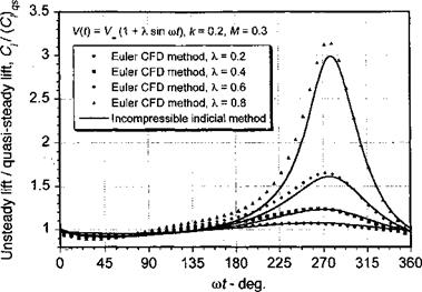
Results calculated using Eq. 8.69 are shown in Fig. 8.26 for the lift on an airfoil at a constant angle of attack, a, experiencing a harmonic oscillation of velocity of the form V(t) = Voo(l + A sin cot) at a reduced frequency, k, of 0.2 with A = 0, 0.2, 0.4, 0.6, and 0.8. The Duhamel integral was solved by means of a finite-difference approximation using the numerical scheme discussed in Section 8.14.1. The lift in Fig. 8.26 is shown as a fraction of the quasi-steady lift, (C[)qs = 2na. Also shown in this figure are results computed by means of a CFD method based on solutions to the Euler equations. It will be seen from Fig. 8.26 that at a given time the primary effect of unsteadiness is either an increase or attenuation

Time-Varying Incident Velocity

Figure 8.26 The effects of a nonsteady free-stream velocity on the unsteady lift for an airfoil with a constant angle of attack. (CFD calculations courtesy of Arun Jose.)

of the unsteady lift compared to the quasi-steady result, which is a result already noted for oscillations in angle of attack. For 0°«wt <90°, the local velocity (and thus the product Va) is increasing. Here, the shed circulation has the opposite sign to the airfoil circulation and so the unsteady lift is less than the quasi-steady value. The higher local velocity here means that the shed wake is further away from the airfoil in a given time, and this effect contributes to a more rapid buildup in the circulatory lift compared to the case where the wake convection speed would be assumed uniform. For 90° <cot< 270°, the local velocity is decreasing. Here, the shed circulation has the same sign as the airfoil circulation, which tends to increase the lift over the quasi-steady value. Furthermore, for 180° < cot < 360° a velocity lower than the mean incident velocity means that the shed wake is closer to the airfoil; this then enhances the basic unsteady effect and the lift quickly becomes much greater than the quasi-steady values. Finally for 270° < cot < 360°, the local velocity is increasing again. With the change in sign of the wake circulation and the increasing wake convection velocity, the lift drops quickly to become close to the quasi-steady value again. Notice that in Fig. 8.26 there is good agreement between the incompressible theory and the CFD method,[32] despite the slight phase differences. Other theoretical work on modeling unsteady free stream velocity effects is given by Ashley et al. (1952) and Friedmann & Yuan (1977). The extension of this problem to subsonic compressible flow is not without its difficulties, but one approach is discussed later in Section 8.17.