Category Principles of Helicopter Aerodynamics Second Edition

Traveling Sharp-Edged Gust: Miles’s Problem

Results for the lift on a thin 2-D airfoil encountering traveling (in-plane convecting) vertical sharp-edged gusts in incompressible flow have been obtained by Miles (1956) in terms of a gust speed ratio, A:

Подпись: (8.59)V

x =————- ,

(V +V,)’

where V is the velocity of the airfoil and Vg is the component of the gust convection velocity in the chord plane of the airfoil. The usual assumption made in most rotor aerodynamic analyses is that the wake (tip vortices and corresponding induced velocity field) are station­ary (nonconvecting) with respect to the rotor (i. e., rigid wake assumption), so that X — 1 at all the blade elements over the rotor disk. However, the self-induced velocities generated by the vortex wake system results in a continuously changing and nonuniform convection of the induced velocity field with respect to the rotor, and this may produce values of X less than or greater than unity.

Miles (1956) showed that as the propagation speed of the traveling gust front, Vg, in­creased from zero to oo (A decreases from 1 to 0), the solution for the unsteady lift changes from the Kiissner result to the Wagner result, with a variety of intermediate transitional re­sults being obtained. Miles’s results were later generalized by Drischler & Diederich (1957) who obtained continuous semi-analytical forms for both the lift and pitching moment gust functions. The problem has also been solved by Leishman (1997) using the reverse flow theorems. All approaches make use of either algebraic or exponential approximations to the Wagner function to facilitate numerical solutions.

Traveling Sharp-Edged Gust: Miles’s Problem Traveling Sharp-Edged Gust: Miles’s Problem Подпись: if x > *o = FA 1 t/c = s/2A, if x < XQ .= FA-1 t/c = s/2A, Подпись: (8.60)

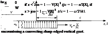
Consider a 2-D airfoil traveling with velocity V and subject to a vertical sharp-edged gust field of magnitude wo convecting with velocity Vg = (A-1 — 1) V, as shown in Fig. 8.22. Notice that when the gust field is stationary, A = 1, and when the field is traveling toward the airfoil at infinite speed, A = 0. For the sharp-edged gust, the primary boundary condition is that the downwash, w, is zero on the part of the airfoil that has not reached the gust front. This means that for a downstream traveling gust referenced to the leading edge then

V
Traveling Sharp-Edged Gust: Miles’s Problem Подпись: (8.61)

and for an upstream traveling gust then

The gust problem is shown schematically in Fig. 8.22. In either case, it will be seen that, like the Kussner problem, the quasi-steady AoA on the airfoil changes progressively as a function of time as the airfoil penetrates into the gust front. For a stationary gust X = 1, and under incompressible flow assumptions, this is equivalent to solving Kussner’s problem. For X == 0, this is equivalent to solving Wagner’s problem.

One approach to solving the convecting gust problem involves using the reciprocal or reverse flow theorems – see Flax (1952, 1953), Brown (1949), Jones (1951), Heaslet & Spreiter (1952), and Leishman (1997). The main utility of reverse flow theorems is that they build from known solutions for airfoil flows and obviate the need to start each new problem from first principles. They are ideally suited to solving various indicial problems, both analytically and numerically. For example, the reverse flow theorems have been used by Leishman (1994) and Hariharan & Leishman (1996) to calculate the indicial responses of airfoils with flaps. General forms of the aerodynamic reverse flow theorems have been established by Heaslet & Spreiter (1952). The first theorem states that: “The lift in steady or indicial motion of one airfoil having arbitrary twist and camber is equal to the integral over the planform of the product of the local AoA and the loading per unit AoA at the corresponding points on a second flat-plate airfoil of identical planform but moving in the reverse direction.” In application, consider two airfoils, one moving in a forward direction and the other in a reverse direction. The first airfoil (the unknown problem) has an arbitrary AoA distribution ai(jci), which could be produced by a vertical gust field (or a flap). The second airfoil is a flat plate at constant angle of attack, аг — constant, which is assumed to have a known aerodynamic loading over the chord. The boundary conditions are «і = a(xi), аг = const. The first reverse flow theorem gives the result that

Подпись: LПодпись: aiACP2dx2.Подпись: (8.62)Подпись: «2 Q,аг&С Pxdx =

In other words, the lift coefficient on the first airfoil can be found from the loading on the second airfoil by integrating the known solution and the local chordwise AoA using

Traveling Sharp-Edged Gust: Miles’s Problem(8.63)

This relatively simple but powerful technique allows some remarkable simplifications in solving both steady and transient airfoil problems. The utility of the theorems, however, extends only to the integrated forces and pitching moments on the airfoil and not to pressure distributions, which may be required for some problems.

For M = 0, the chordwise pressure loading for an indicial change in AoA is given by Eq. 8.46. By using the reverse flow theorems, the time-varying (indicial) lift on the airfoil for a traveling sharp-edged vertical gust can be obtained by integration of this known solution over the appropriate part of the airfoil affected by the gust front, but when the airfoil is moving in the reverse direction. For the downstream traveling vertical gust, this is equivalent to integrating the known flat-plate loading from the trailing edge to the leading edge of the gust front at Jc0 (see Fig. 8.22). For the upstream traveling gust, the known loading must be integrated from the leading edge of the airfoil up to xo. It will be immediately apparent that different results, both quasi-steady and unsteady, will be produced for downstream versus upstream traveling vertical gusts.

For incompressible flows, the noncirculatory part of the unsteady lift can be written in terms of the instantaneous up wash over the airfoil. For a traveling sharp-edged vertical gust, results can be obtained analytically by integrating the first term of Eq. 8.46 with the boundary conditions given in Eqs. 8.60 and 8.61. For a downstream traveling gust the noncirculatory lift can be shown to be

Traveling Sharp-Edged Gust: Miles’s Problem(8.64)

where во = cos_1(l — 2jco), so that 9q = 0 at the time when the gust front is at the airfoil leading edge and во = ж at the trailing edge. For the upstream traveling sharp-edged vertical gust, the corresponding result for the noncirculatory lift is

Traveling Sharp-Edged Gust: Miles’s Problem(8.65)

Подпись: Equations 8.64 and 8.65 can be evaluated numerically at discrete values of time as the gust

front proceeds over the airfoil, with the time derivatives being evaluated by means of finite differences.

Unlike the apparent mass terms, the circulatory parts of the unsteady lift depend on the prior time history of the gust field, and so the lift must be obtained numerically by Duhamel superposition (see Section 8.14.1 for details). For a downstream traveling gust, the quasi-steady part of the circulatory lift can be obtained analytically by integration of the second term in Eq. 8.46 with the application of the appropriate boundary conditions. For the downstream traveling sharp-edged gust, it can be shown (see Question 8.12) that

the quasi-steady circulatory lift is

Подпись: (8.66)Cqs

-—L— = 2(тг – в0 – sin6>0) (w0/V)

Traveling Sharp-Edged Gust: Miles’s Problem
or, in terms of equivalent angle of attack,

The net unsteady circulatory lift is then determined numerically by Duhamel superposition with the instantaneous or quasi-steady equivalent AoA and the Wagner function using Eq. 8.50. The calculation of the corresponding unsteady pitching moments proceeds by a similar process. This problem, however, is somewhat more difficult to solve because a second reverse flow theorem and the chordwise loading as a result of pitch rate must be used in addition to the AoA result – see Leishman (1997).

Results for the unsteady lift and pitching moment for downstream traveling sharp-edged gusts are shown in Fig. 8.23. For A = 0 (Vg = ±oo), the results lead to the Wagner function. For A = 1 (Vg = 0), the results reduce to the Kiissner function. For intermediate values of A, notice that a different series of results are obtained as the gust propagation speed increases from zero (A = 1). The noncirculatory term is responsible for the very large peaks in the lift that are produced as A decreases. The lift reaches a maximum at the point when the airfoil is about naif way into the gust. It can be seen that the magnitudes of these peaks are often larger than the steady-state lift coefficient of 2ж per radian angle of attack. For vertical gusts that move with the wing at velocities less than 0 (A > 1), the noncirculatory part of the lift is small and the circulatory lift grows only very slowly with time. The corresponding pitching moment shows a change in the sign of the center of pressure for A greater or less than one. For the stationary gust (A = 1), the center of pressure remains at the 1/4-chord throughout the motion, a result proved analytically by von Karman & Sears (1938). As the gust speed approaches infinity, the peak in the pitching moment approaches —7T<$(f) with the center of pressure moving to mid-chord. For receding vertical gusts, the center of pressure moves in front of the 1 /4-chord.

Results for upstream traveling vertical gusts are shown in Fig. 8.24. Again, for quickly traveling gusts the results approach the Wagner function. For progressively slower gusts, large peaks in the lift and pitching moment appear as a result of the noncirculatory contribu­tions to the airfoil loading. Notice that the noncirculatory terms are the same for any value of |A| but that the total transient value of the lift is higher than for a downstream traveling gust. The reasons for this will be apparent from a comparison of Eqs. 8.67 and 8.68, which simply prove that a gust affecting the trailing edge of the airfoil will have a larger effect on the circulatory lift than a gust affecting the same percentage of the leading edge. For the same reasons, a trailing edge flap deflection is more effective in producing a change in lift than a leading edge flap.

Sharp-Edged Gust: Kiissner’s Problem

In a rotor flow field, the rotor wake (and specifically the tip vortices) produces a highly nonuniform induced velocity field across the plane of the rotor disk. Therefore, a typical blade element encounters a nonuniform vertical upwash/downwash as it rotates in this field. It is, therefore, important to distinguish properly the effects on the airloads arising from AoA changes from blade motion (in effect, a plunging and pitching motion at the blade element) from the effects resulting from the rotor wake-induced velocity field (in effect, a vertical gust velocity normal to the blade element). This distinction has important effects on the resulting airloads and should not be overlooked in the mathematical modeling of helicopter rotor problems.

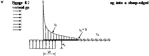
The problem of finding the transient lift response on a thin-airfoil entering a sharp-edged vertical gust (that is, a vertical upwash velocity) was first tackled by Kiissner (1935) and properly solved by von Karman and Sears (1938). In this problem, the upwash velocity, wg, is defined relative to an axis at the leading edge as

Sharp-Edged Gust: Kiissner’s Problem(8.54)

as shown in Fig. 8.20. Recall that, in Wagner’s problem, the AoA changes instantaneously over the whole chord at s — 0. In Kussner’s problem, however, the quasi-steady AoA changes progressively as the airfoil penetrates into the gust front. At s = 2, the airfoil becomes fully immersed in the gust. The resulting variation in the lift coefficient can be written in a similar way to Wagner’s solution such that

Sharp-Edged Gust: Kiissner’s Problem(8.55)

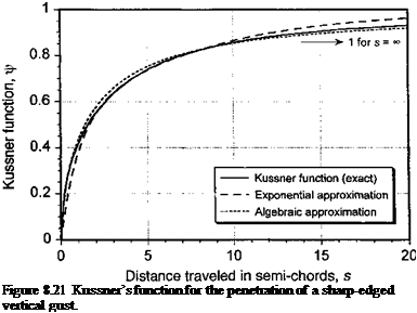
where yjs(s) is known as Kiissner’s function and is plotted in Fig. 8.21. Compared to the Wagner function, which has an initial value of one-half, it will be seen that the Kiissner function builds from an initial value of zero and asymptotes to unity for s -» oo. Kussner’s function is also known exactly, albeit not in a convenient analytic form. Von Karman & Sears (1938) also showed that the aerodynamic center always acts at the 1/4-chord of the airfoil for all s. This is perhaps a surprising result, but it has been verified experimentally – see Sears & Sparks (1941).

The Kiissner function can be used with the Duhamel superposition integral to find the lift response to an arbitrary vertical upwash field, where the lift coefficient can now be obtained using

Подпись: (8.56)

Sharp-Edged Gust: Kiissner’s Problem

2тг ( Ґ dwJa)

Подпись: Figure 8.21 Kussner’s function for the penetration of a sharp-edged vertical gust.

Q(t) = — ( wg(0)l/(s) + j^ ~ v)dcr

Notice that this equation is analogous to the result for the lift resulting from arbitrary varia­tions in angle of attack, as given previously in Eq. 8.50, but with a different indicial function being used. To enable practical calculations using Duhamei superposition, the Kiissner func­tion, like the Wagner function, is usually replaced by an exponential approximation. One approximation is given by Sears & Sparks (1941) as

f(s) « 1 – 0.5e~ai3s – 0.5e~1(k, (8.57)

Подпись: f(s) Подпись: s2 + s s2 + 2.825 +0.80’ Подпись: (8.58)

which is shown in Fig. 8.21. Alternatively, an algebraic approximation that is sometimes used for the Kiissner function is

which is given by Bisplinghoff et al. (1955). Neither approximation represents the correct vertical tangent of the Js curve at s = 0, but this is of no practical significance.

Indicial Response: Wagner’s Problem

Theodorsen’s lift deficiency approach has found use in many problems in both fixed-wing and helicopter aeroelasticity. However, for a rotor analysis Theodorsen’s theory is somewhat less useful because the nonsteady value of velocity at the blade elements, V = Uj(y, jf), means that the argument к (the reduced frequency) is, strictly speaking, an ambiguous parameter. Therefore, a theory formulated in the time domain is more general and is usually more useful. Wagner (1925) has obtained a solution for the so-called indicial lift on a thin-airfoil undergoing a transient step change in AoA in an incompressible flow.[30] The transient chordwise pressure loading is given by

ACp(x, s) 4 /——— з 11 — x

————– = — 5(f)>/(l – x)x + 40(j)J ——, (8.46)

a V у x

where <fi(s) is called Wagner’s function and, by analogy with the Theodorsen function, accounts for the effects of the shed wake. As defined previously in Eq. 8.4, the variable s represents the distance traveled by the airfoil in semi-chords. The first term in Eq. 8.46 is the apparent mass contribution, which for a step input appears as a Dirac-delta function S(t). The corresponding result for an indicial change in pitch rate about the leading edge is given by

ACp(x, j) = ^(1+2jc)V(l -*)*+( 30(5) – l) УЦ^-НЦ/(1 – ф. (8.47)

Again, the first term is an apparent mass term, with the second term being circulatory in nature and is affected by the shed wake. The third term is a quasi-steady term, with an analogous term also appearing in Theodorsen’s result.

Wagner’s function, 0(s), is known exactly [see, for example, Lomax (1968)] and is plotted in Fig. 8.19. Notice that the noncirculatory or apparent mass loading is responsible for the initial infinite pulse at 5 = 0. Thereafter, the function builds asymptotically from one half to a final value of unity as s —> oo. In Wagner’s problem, the aerodynamic center is at mid-chord at s = 0 and moves immediately to the 1 /4-chord for s > 0. The resulting variation in the lift coefficient for a step change in angle of attack, a, can be written as

CKO = ^S(t) + 271 a<Ks), (8.48)

where 2na is the steady-state lift coefficient, as given by steady thin-airfoil theory.

For rotor analyses, the indicial lift response makes a useful starting point in the devel­opment of a general time domain unsteady aerodynamic theory. If the indicial response is known, then the unsteady loads to arbitrary changes in AoA can be obtained through the superposition of indicial aerodynamic responses using the Duhamel integral. Consider a general system in response to a general forcing function f(t), t > 0. If the indicial response

Distance traveled in semi-chords, s

Figure 8.19 Wagner’s function for a step change in angle of attack.

ф of the system is known, then the output y(t) of the system can be written in terms of Duhamel’s integral as

Indicial Response: Wagner’s Problem

Indicial Response: Wagner’s Problem
Подпись: 10 Подпись: 20
Подпись: 0 Подпись: 5

(8.49)

Indicial Response: Wagner’s Problem Подпись: (8.50)

See Section 8.14 and Bisplinghoff et al. (1955) or von Karman & Biot (1940) for details. In Eq. 8.49, cr is simply a dummy time variable of integration, and the first term is related to the initial condition from which subsequent inputs are applied. By analogy with Eq. 8.49, the circulatory part of the lift coefficient, Cf, in response to an arbitrary variation in AoA can now be written in terms of the Wagner function as

where ae simply represents an effective AoA and contains within it all of the time history effects on the lift because of the influence of the shed wake. Notice that if V = constant, then s = 2 Vt/с. In addition, the appropriate apparent mass terms must be added to get the total lift. For incompressible flow, however, the apparent mass terms are proportional to the instantaneous motion, so they all conveniently appear outside the Duhamel integral.

Indicial Response: Wagner’s Problem Подпись: (8.51)

The Duhamel integral in Eq. 8.50 can be solved analytically or numerically. Analytical solutions are mostly restricted to simple forcing functions, and numerical methods must be employed in the general case. The main difficulty in solving Duhamel’s integral is, however, with the Wagner function itself. Although the Wagner function is known exactly, its evaluation is not in a convenient analytic form. Therefore, it is usually replaced by a simple exponential or algebraic approximation. When this is done, a whole series of practical numerical tools for computing the unsteady aerodynamics can be unleashed. One approximation to the Wagner function, attributed to R. T. Jones (1938, 1940), is written as a two term exponential series with four coefficients, that is,

as shown in Fig. 8.19. This approximation is found to agree with the exact solution to an accuracy that is within 1%. Another approximation to the Wagner function is attributed to W. P. Jones (1945); here

Подпись: (8.52)0(j) ^ 1.0 – 0.165е_0 04ь – 0.335e_0-32*

In each case it will be noted that A + A 2 — 0.5, according to Wagner’s exact result.

The main advantage of using the exponential approximation is that it has a simple Laplace transform. While the exponential behavior of the Wagner function is not an ex­act representation of the physical behavior, it is usually sufficiently accurate for practical calculations.[31] An alternative algebraic approximation to the Wagner function suggested by Garrick (1938) is

Indicial Response: Wagner’s Problem(8.53)

which, although not as accurate as the exponential approximation except in the limit as s -> oo, it agrees with both the exact solution and with the exponential approximation to within 2% accuracy.

Sinusoidal Gust: Sears’s Problem

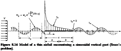
Von Karman & Sears (1938) analyzed the problem of a thin-airfoil moving through a sinusoidal vertical gust field. This is also a frequency domain solution. The gust can be considered as an upwash velocity that is uniformly convected by the free stream, as shown

Sinusoidal Gust: Sears’s Problem Подпись: (8.38)

in Fig. 8.16. The forcing function in this case is

where ajg is the gust frequency. There are two cases of interest. First, if the gust is referenced to the airfoil leading edge then x = 0 and so Eq. 8.38 simply becomes wg(t) = sincogt. Second, if the gust is referenced to the mid-chord, then x = b = c/2 and the forcing becomes wg{t) — cos kg sin aogt — sin kg cos aogt, which is equivalent to a phase shift (see also Question 8.6). The mid-chord was the reference point used in the original work of

Подпись: Figure 8.16 Model of a thin airfoil encountering a sinusoidal vertical gust (Sears’s problem).

von Karman & Sears (1938). In this case, the final result for the lift coefficient can be

written as

Ci = 2 n(^jS(kg)ei2nVIX*, (8.39)

where S(kg) is known as Sears’s function. The gust encounter frequency is given by, 2 nb

kg = — , (8.40)

Ag

where kg is the wavelength of the gust (see Fig. 8.16). Sears’s function can also be computed exactly in terms of Bessel functions and is given by

S(kg) = (J0(kg) — і Ji(kg))C(kg) + iJ{kg) (8.41)

or in terms real and imaginary parts as

mS(kg) = F(kg)J0(kg) + G(kg)Ji(kg), (8.42)

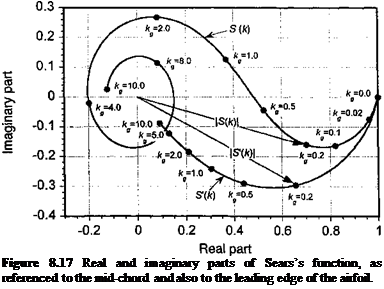
Подпись: Figure 8.17 Real and imaginary parts of Sears’s function, as referenced to the mid-chord and also to the leading edge of the airfoil.

%S(kg) = G(kg)J0(kg) – F(kg)Mkg) + Ji(*g). (8.43)

If the gust is referenced to the leading edge of the airfoil, the result must be transformed, as described previously. This function will be called S’ and can be written as

mS'(kg) = VIS cos kg+%S sin kg, (8.44)

%S'(kg) = — 9^5 sin&g + %S coskg, (8.45)

which is equivalent to a frequency dependent phase shift. The two results are plotted in Fig. 8.17. Notice that the peculiar spiral shape of the S transfer function arises only when the gust front is referenced to the mid-chord of the airfoil. If the gust response is computed relative to the leading edge, then the S’ transfer function is obtained. In application, the gust front reference point is frequently confused in the published literature. While the differences are small at low reduced frequencies, the errors will be significant for kg > 0.2.

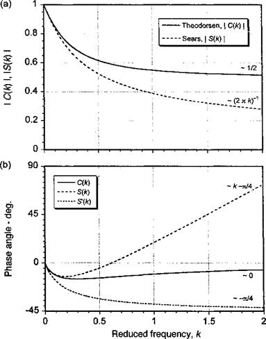
The Sears function and the Theodorsen function are compared in Fig. 8.18 in terms of amplitude and phase angle as a function of reduced frequency. At low reduced frequencies the functions converge, but for к > 0.1 the differences become increasingly large. Notice

Sinusoidal Gust: Sears’s Problem

Figure 8.18 The Theodorsen and Sears functions in terms of amplitude and phase angle as a function of reduced frequency, (a) Amplitude, (b) Phase.

that as к —>• oo then |C(&)| -> 1/2, and the corresponding phase angle -» 0. For Sears’s function, the asymptotic behavior is |S(fcg)| oc l/^/lnkg. When referenced to the mid­chord, then phase angle is proportional to kg — я/4, or —7г/4 if the leading edge of the airfoil is used as the reference point.

The Returning Wake: Loewy’s Problem

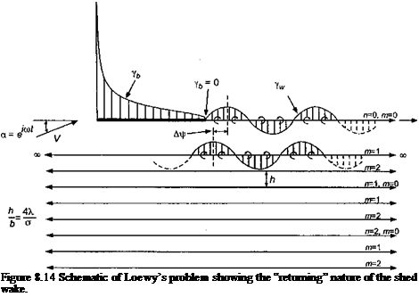
Theodorsen’s theory has represented an isolated 2-D thin-airfoil with the wake convected downstream to infinity. For rotorcraft work, this is perhaps a questionable as­sumption because the rotor blade sections may encounter the wake vorticity from previous blades as well as the returning wake from the blade in question. This fact was acknowledged by Loewy (1957) and by Jones (1958) who set up a model of a 2-D blade section with a returning shed wake, as shown in Fig. 8.14.

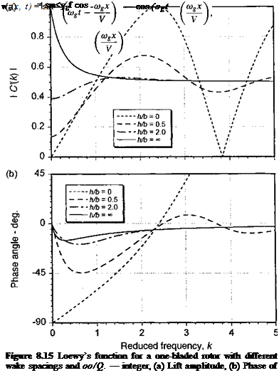
This returning wake can be modeled with planar 2-D vortex sheets, just as in Theodorsen’s method, but now with a series of sheets below the airfoil with vertical separation, h, that depend on the mean induced velocity through the rotor disk and the number of rotor blades. Loewy (1957) has shown that in this case the lift on the blade section can be expressed by replacing Theodorsen’s function by

c(k. h) = -______ + _________ , (8.33)

to J Hf(k) + iH^(k) + 2(Ji(k) + iJ0(k))W

where C'(k) is known as the Loewy function, with argument of reduced frequency k. For a single blade, the complex valued W function is given by

Подпись: (8.34)w(^—, — ^ = (eM/bei2n(.a>/a) _ jj-i

Подпись: Figure 8.14 Schematic of Loewy’s problem showing the “returning” nature of the shed wake.

If a)/ £2 = an integer, then all the shed wake effects are in phase. Notice from Eqs. 8.33 and 8.34 that as h —oo then W■ —► 0 and C'(k) -> C(k), and Loewy’s function approaches

Theodorsen’s result, as it should. For a rotor with Nb blades, the W function is modified to read

W(t’ I’ AVf’ = – l)~’ , (8.35)

where the parameter aj/NbSl now controls the wake phasing.

The wake spacing ratio h/b can be determined from the spacing of the helical vortex sheets that are laid down below the rotor. If an average induced velocity u, = XQR is assumed, then during a single rotor revolution the shed wake generated by a single blade will be at a distance h = (2я/ Q)v, below the rotor. For multiple blades, the spacing will be (27t)Vi/(QNb), that is,

Подпись: (8.36)h X£IR2ti AX

b QNbb о with a as the rotor solidity. For = 0, which means that the only phase shift in the wake vorticity results from the spacing between the blades, then

Подпись: (8.37)W(~t’ ЇІ’ °’ = (ekh/bei27t(a>/NbQ) – 1) 1 .

Representative results from Loewy’s theory for a one-bladed rotor are shown in Fig. 8.15, where we see that the main consequence of including the shed vorticity below the blade is that it serves to amplify or attenuate the unsteady lift response, depending on the reduced frequency, wake spacing, and wake phase. The most important effects are for lower reduced frequencies, with oscillations at the harmonics of the rotor rotational frequency. Using typical helicopter values of X ^ 0.05 and <7—0.1 gives h/b ^ 2. Therefore, for a helicopter rotor the Loewy function predicts that C’ ~ 0.5 over most of the reduced frequency range, which is an important effect. This can lead to lower damping of blade flapping and flapwise elastic bending modes and will increase the vibratory response of the blade to harmonic airloads. However, it is only for very low advance ratios or for hover that the Loewy effect seems important. Daughaday et al. (1959) have conducted indirect validation of the Loewy effect from measured blade flap bending moments and transient flapping decay data. The reduction in flap damping at frequencies that were multiples of the rotor rotational frequency was verified. Other verifications of the Loewy effect and the implications for rotor aeroelasticity have been made by Ham et al. (1958), Silviera & Brooks (1959), and Anderson & Watts (1975). Hammond & Pierce (1972) have considered a development of the Loewy problem for subsonic compressible flow. Whereas the effects of compressibility are small for со/ £2 near unity, larger differences are noted for co/Q < 1. No equivalent analytic theory to the Loewy problem is available for forward flight; the only option is to solve the problem numerically through discrete vortex wake tracking, a problem discussed in Chapter 10.

Pitching Oscillations

For harmonic pitch oscillations, additional terms involving pitch rate a appear in the equations for the aerodynamic response. The forcing is now given by a = aelcot, and the pitch rate by a — iwotelwt. In this case, the lift coefficient is

Подпись: 'muPitching Oscillations

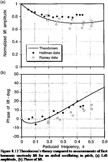
Подпись: Figure 8.12 Theodorsen’s theory compared to measurements of first harmonic unsteady lift for an airfoil oscillating in pitch, (a) Lift amplitude, (b) Phase of lift.
Подпись: The corresponding pitching moment about mid-chord is

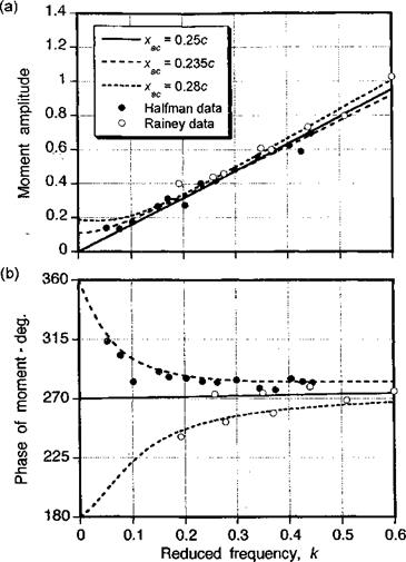
(8.32)

The results from these predictions are compared with experimental measurements in Figs. 8.12 and 8.13, again in terms of the normalized lift and pitching moment amplitude about the 1 /4-chord (using Eq. 8.28) and their corresponding phase angles versus reduced frequency. In addition to the low Mach number results of Halfman (1951), this figure shows data measured by Rainey (1957), which are for a Mach number of about 0.3 and a Reynolds number of 5.3 x 10⁶. It is significant in the latter case that a reduced frequency of up to 0.6 was obtained in the experiment, which gives a good opportunity to examine the validity of the linearized incompressible aerodynamic theory at higher reduced frequencies. As shown in Fig. 8.12, the lift amplitude initially decreases with increasing к because of the effects of the shed wake. The amplitude’begins to increase again for к > 0.5 as the apparent mass

Pitching Oscillations

Figure 8.13 Theodorsen’s theory compared to measurements of first harmonic unsteady pitching moment for an airfoil oscillating in pitch, (a) Pitching moment amplitude about 1/4-chord, (b) Phase of pitching moment.

forces begin to dominate the airloads. This is also shown by the phase angle, which exhibits an increasing lead for к > 0.3. For the lift amplitude, Theodorsen’s theory compares well with Rainey’s results. The agreement with Halfman’s results are not quite as good for the lift amplitude but are better in phase. In Fig. 8.13 it is apparent that the amplitude of the 1/4-chord pitching moment increases quickly with increasing k, with the agreement of theory and experiment being excellent. Again, the phase of the pitching moment response shows a behavior that can be explained in terms of shift of the aerodynamic center from the 1 /4-chord. As for the plunging case, Halfman’s data suggest an aerodynamic center at 23.5% chord. Rainey’s data, however, suggest that the aerodynamic center is further back at 28% chord. Overall, the correlation obtained between Theordorsen’s theory and experimental measurements for airfoils oscillating in pitch and plunge is quite good, giving considerable support to the validity of Theodorsen’s theory, at least for low Mach numbers and up to moderate values of reduced frequency.

Pure Plunging Oscillations

Consider now a harmonic plunging motion, such as would be contributed by blade flapping. Here, the forcing is h = hel(0t so that h = io)hel<ot and h = —a>2hel(0t. Substituting into the expression for the lift given by Eq. 8.13 and solving for the lift coefficient gives

Сі = [ 2ттк(і F-G) – rf] ^eicot. (8.29)

Again, the complete term inside the square brackets can be considered as the lift transfer function. Notice that for this problem the circulatory part of the lift response leads the forcing displacement h by a phase angle of ж/2. Also, the apparent mass force leads the circulatory part of the response by a phase angle of ж/2 or the forcing by a phase angle of ж. The corresponding pitching moment about mid-chord for this case is

Подпись: (8.30)

Подпись: Figure 8.9 Circulatory and apparent mass contributions to the normalized unsteady lift response for a pure sinusoidal AoA oscillation, (a) Lift amplitude, (b) Phase of lift.

C

mi’2 – f 4 )K ь

Pure Plunging Oscillations

Figure 8.10 Theodorsen’s theory compared to measurements of first harmonic unsteady lift for an airfoil oscillating in plunge, (a) Lift amplitude, (b) Phase of lift.

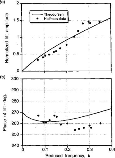
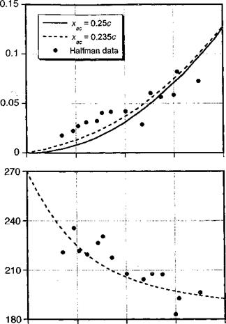
A comparison of Theodorsen’s result with experimental data for an airfoil oscillating in plunge is shown in Figs. 8.10 and 8.11. The results are plotted as a the first harmonic normalized amplitude of the lift and pitching moment about the 1/4-chord and their cor­responding phase angles as functions of reduced frequency. The experimental results are taken from Halfman (1951), where measurements were made on an oscillating NAC A 0012 airfoil. These tests were conducted for Mach numbers less than 0.1 and a Reynolds number of approximately 106. It is significant, however, that a relatively high reduced frequency of 0.4 was attained in the experiment. Figure 8.10 shows that there is good agreement be­tween Theodorsen’s theory and Halfman’s measurements. Notice the sign of the lift phase angle, which changes from a lag (less than 270° or minus 90°) to a lead (greater than minus 90°) at higher reduced frequencies as the noncirculatory effects become more dominant. Notice also in Fig. 8.11 that the phase of the pitching moment shows a significant digression from the results obtained with the baseline Theodorsen theory, which predicts a phase lag of 180°. However, this behavior can be explained by the fact that the aerodynamic center

Pure Plunging Oscillations

(a)


(b)


O)

Ф

■O


c

Ф

£

о

E


ф

w

со

JZ

CL


0 0.1 0.2 0.3 0.4

Reduced frequency, к


Figure 8.11 Theodorsen’s theory compared to measurements of first harmonic unsteady pitching moment for an airfoil oscillating in plunge, (a) Pitching moment amplitude about 1 /4-chord, (b) Phase of pitching moment.


Pure Plunging OscillationsPure Plunging Oscillations

Pure Plunging Oscillations

location is not at the 1 /4-chord; the results in this case suggest an aerodynamic center for this airfoil and test conditions that is located at 23.5% chord.

Pure Angle of Attack Oscillations

L = 2л pV[28]b

Pure Angle of Attack Oscillations Подпись: ae Подпись: (8.24)

It is now possible to consider the effects of both the circulatory and the noncircu – latory contributions to the unsteady lift. Consider first a pure harmonic variation in a, that is, a = aelwt. Substituting into the expression for the lift given by Eq. 8.13 yields

О

Подпись: 1.2 1 0.8 Подпись: u.z 0 -0.2 Подпись: -2Подпись:Подпись: 10Подпись:Pure Angle of Attack OscillationsПодпись: 12c

Ф

о

it=

Q)

О

О

In terms of the lift coefficient, the result is

Q = = 2n(F + iG) + ink] аеіш. (8.25)

pV2b L J

The term inside the square brackets can be considered the lift transfer function, which ac­counts for the difference between the unsteady and quasi-steady airloads. The first term inside the brackets is the circulatory term, and the second term is the apparent mass contri­bution. Notice that the apparent mass contribution is proportional to the reduced frequency and leads the forcing by a phase angle of n/2. If the result is normalized by 2na then

-^ = (F + iG) + i|. (8-26)

2тг|а| 2

The equivalent result for the pitching moment about mid-chord is

Подпись: (8.27)|Cm, J.7Г к

№ ~~lT

and where the moment about the 1/4-chord is obtained by a transformation using

Cmi/) = C„m – (8.28)

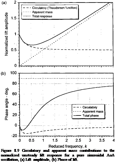
The results for the unsteady lift are shown in Fig. 8.9, where the significance of the apparent mass contribution to both the amplitude and phase can be appreciated. At lower values of reduced frequency (say, к < 0.1) the noncirculatory or apparent mass forces are small, and the circulatory terms dominate the solution. At higher values of reduced frequency, the apparent mass forces clearly dominate. By setting C(k) = 1, that is, F = 1 and G = 0 in Eq. 8.26, the effects of the shed wake are removed and the quasi-steady result is obtained.[29]

. Theodorsen’s Theory

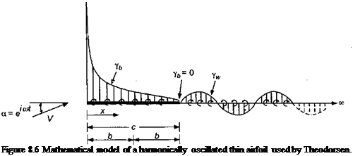
Theodeorsen’s theory, which is widely used by fixed-wing analysts, forms one root for many of the unsteady aerodynamic solution methods used for helicopter analysis. The problem of finding the airloads on an oscillating airfoil was first tackled by Glauert (1929), but was properly solved by Theodorsen (1935). Theodorsen’s approach gives a solution to the unsteady airloads on a 2-D harmonically oscillated airfoil in inviscid, incompressible flow, and subject to small disturbance assumptions. The basic model is shown in Fig. 8.6. Both the airfoil and its shed wake are represented by a vortex sheet, with the shed wake extending as a planar surface from the trailing edge downstream to infinity. The shed wake comprises countercirculation that is shed at the airfoil trailing edge and is convected downstream at the free stream velocity. The assumption of a planar wake is justified if the AoA disturbances remain relatively small. As with the standard quasi-steady thin-airfoil theory, the bound vorticity, уь, can sustain a pressure difference and, therefore, a lift force. The wake vorticity, yw, however, must be force free with zero net pressure jump over the sheet.

Theodoisen’s problem was tu obtain the solution for the loading, y^, on the airfoil surface under harmonic forcing conditions. The governing integral equation is

Подпись: (8.9)± Г dx+— Г ^iHdx

2n Jo (x – X0) 27Г Jc (x – x0)

Подпись: Figure 8.6 Mathematical model of a harmonically oscillated thin airfoil used by Theodorsen.

where w is the downwash on the airfoil surface. This equation must be solved subject to invoking the Kutta condition at the trailing edge [i. e., уь(с, t) = 0]. There is also a connection to be drawn between the change in circulation about the airfoil and the circulation shed into

. Theodorsen’s Theory Подпись: (8.10)

the wake. Conservation of circulation requires that

Assuming that the shed vortices are convected at the free stream velocity, V, this gives dx = Vdt and so

Подпись:. Theodorsen’s Theory(8.11)

(8.12)

This wake vorticity changes the downwash velocity over the airfoil and, therefore, the loads on the airfoil are also affected. So long as the circulation about the airfoil is changing with respect to time, circulation is continuously shed into the wake and will continuously affect the aerodynamic loads on the airfoil. In the limit as the forcing becomes zero, the shed wake vorticity cast off the trailing edge of the airfoil becomes zero, and the remaining circulation in the wake convects downstream to infinity. In this case, the problem is modeled by the standard quasi-steady thin-airfoil theory.

. Theodorsen’s Theory

The unsteady problem posed above is certainly not trivial to solve, but for simple har­monic motion the solution is given by Theodorsen (1935) in a form that represents a transfer function between the forcing (angle of attack) and the aerodynamic response (pressure dis­tribution, lift, and pitching moment). Theodorsen’s approach is summarized by Bisplinghoff et al. (1955) and by another approach attributed to Schwarz. See also Bramwell (1976) and Johnson (1980) for a good exposition of the theory. For a general motion, where an airfoil of chord c = 2b is undergoing a combination of pitching (a, dr) and plunging (h) motion in a flow of steady velocity V, Theodorsen gives for the lift

. Theodorsen’s Theory(8.13)

. Theodorsen’s Theory

where a is the pitch axis location relative to the mid-chord of the airfoil and is measured in terms of semi-chords. The corresponding moment about mid-chord is

. Theodorsen’s Theory(8.14)

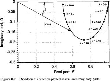
The first set of terms in Eqs. 8.13 and 8.14 result from flow acceleration effects (i. e., a noncirculatory or apparent mass effect). The second terms arise from the creation of circulation about the airfoil (i. e., a circulatory effect). The circulatory term C(k) = F(k) + і G(k) is a complex valued transfer function known as Theodorsen’s function, which accounts for the effects of the shed wake on the unsteady airloads.

The noncirculatory or apparent mass terms arise from the дф/St term contained in the unsteady Bernoulli equation (Kelvin’s equation) [see Karamcheti (1966)] and account

. Theodorsen’s Theory

It will be appreciated from Fig. 8.7 that Theodorsen’s function serves to introduce an amplitude reduction and phase lag effect on the circulatory part of the lift response compared to the result obtained under quasi-steady conditions. The basic effect can be seen if a pure oscillatory variation in AoA is considered, that is, a = aelwt. In this case2 the circulatory part of the airfoil lift coefficient is given by

Сі = 2л a C(k) = 2л a [F(fc) + iG(k)]. (8.23)

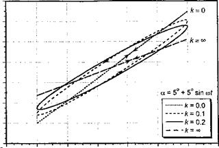
Representative results from the Theodorsen model are shown in Fig. 8.8. For к = 0 the steady-state lift behavior is obtained, that is Q is linearly proportional to a. However, as к is increased, the lift plots develop into hysteresis loops, and these loops rotate such that the amplitude of the lift response (half of the peak-to-peak value) decreases with increasing reduced frequency. These loops are circumvented in a counterclockwise direction such that the lift is lower than the steady value when a is increasing with time and higher than the steady value when a is decreasing with time (i. e., there is a phase lag). Notice that for infinite reduced frequency the circulatory part of the lift amplitude is half that at к = 0 and there is no phase lag angle.

Principles of Quasi-Steady Thin-Airfoil Theory

The unsteady airfoil problem can be tackled initially starting from the classical, incompressible, steady, thin-airfoil theory, which is described in Section 14.8. This is equiv­alent to setting all the unsteady terms in the governing flow equations equal to zero and will be called the quasi-steady problem. At the most elementary level it is convenient to think of oscillatory motion of the airfoil. This motion can be decomposed into contributions associated with AoA (which is equivalent to a pure plunging motion) and contributions associated with pitching (which includes contributions from both AoA and pitch rate) – see Fig. 8.4.

Principles of Quasi-Steady Thin-Airfoil Theory

Principles of Quasi-Steady Thin-Airfoil Theory

Figure 8.4 Unsteady oscillatory forcing can be considered to have contributions from both plunging and pitching motion, including rate terms.

Principles of Quasi-Steady Thin-Airfoil Theory Principles of Quasi-Steady Thin-Airfoil Theory
Подпись: V
Principles of Quasi-Steady Thin-Airfoil Theory

Figure 8.5 Velocity perturbation normal to chord and effective induced camber for plunge velocity and pitch rate about an axis located at 1 /4-chord.

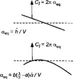
The unsteady motion of the airfoil produces a distribution of perturbation velocity normal to the chord, for which a solution to the vortex sheet strength on the airfoil, уь, can be found to maintain flow tangency on the chordline. An angle of attack, a, or plunge velocity, h, produces a uniform velocity perturbation w that is normal to the chord, as shown in Fig. 8.5. For an AoA perturbation, w{x) = Va = constant. Similarly, for a steady plunge velocity, w(x) = —h = constant. The pitch-rate term produces a linear variation in normal perturbation velocity. For a pitch rate imposed about an axis at a semi-chords from the mid-chord, then w(x) = —a(x — ab), so that the induced camber is a parabolic arc, as also

о c

M1UW11 111 I’lg. O. J.

The quasi-steady contribution to the airloads follows directly from thin-airfoil theory (Section 14.8) using the following solutions for the Fourier harmonics:

Ao = ot — — J and An = —J cos nOdO, (8.5)

Подпись: Ci = 2TC Подпись: a -1 Ь b V Подпись: a V Подпись: (8.6)
Principles of Quasi-Steady Thin-Airfoil Theory

where x = —b cos 9 based on a coordinate system at mid-chord. The results for this problem are summarized in Table 8.1. The quasi-steady lift and pitching moment are then

Подпись: (8.7)я ab

47’

and

Principles of Quasi-Steady Thin-Airfoil Theory(8.8)

For a pitching axis at the 1 /4-chord (a = — 1 /2), the term inside the square brackets in Eq. 8.6 will be seen to be the effective AoA at the 3/4-chord. If a = 1/2 then no lift is produced by pitch rate about 3/4-chord, and for this reason the 3/4-chord point is sometimes called the rear neutral point. Also, note that the pitching moment about the 1 /4-chord resulting from the pitch rate contribution is independent of the pitch axis location, a (see Question 8.2).