Category A PRACTICAL. APPROACH TO. ROBUSTNESS. ANALYSIS

MORTON’S METHOD

MORTON’S METHOD

This method is illustrated in the specific context of the missile ex­ample. The same result as in the previous subsection is obtained. The idea is to rewrite equations (2.11) of the linearized missile model as:

with:

Подпись:QS

Mass * V QSd

h

Подпись: (4.3)QS

Mass * д

MORTON’S METHOD

Ma = (1 + ^)М° Ms = (1 + S2)Ms Za = (1+*з)Я“ Zs = (1 + ВД0

As in the previous subsection, the tail deflection input S is renamed as u. Let then:


(4.4)


Equation (4.2) is rewritten as:

a

q

и


(4.5)


with:


Г CxZl 1 CxZg C2Ml 0 C2M$ . C3Z° 0 c3z


(4.6)


Po


and:


Pi

P2

Рз


MORTON’S METHOD

T

= uxv{ T

= ulv2 T

= u2v T

– U2v2


Pa


t

ui

T

Щ

T

Ъ

T

u2


(4.7)


MORTON’S METHOD

The above equations can thus be rewritten as:

= (Po + BAC) with Д = diag(6i, S2, S3, $4) and:

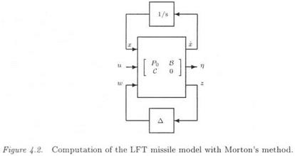
Let the augmented plant with additional fictitious inputs w and outputs z:

Подпись: ' a " ' a ’ Q ' Po В Я V . c 0 . и . z . . w .

MORTON’S METHOD

(4.10)

When applying the fictitious feedback w = Az, the initial plant of equation (4.8) is recovered. The LFT model is given in Figure 4.2 (with x = [a, g]).

APPLICATIONS

The computation of the LFT models of the missile and transport air­craft is detailed in this chapter.

1. THE MISSILE

1.1 A PHYSICAL REPRESENTATION

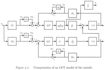
In the same way as at the end of the previous chapter, the para­metric uncertainties in the stability derivatives are directly introduced in the physical missile model. Figure 4.1 represents equations (2.11) of the linearized missile model, with multiplicative uncertainties Si being introduced in the stability derivatives MQ, Ms, Za and Zs (i. e. MQ is e. g. replaced by (1 – t – 6)Ма). Note that the tail deflection input £ is renamed as и in this figure, in order to avoid any ambiguity with the vector <5 of parametric uncertainties.

The LFT model of the missile is obtained as:

Подпись: ■n 4 (4.1)

where Д = diag(6, 62,63,64) and His) is the transfer in Figure 4.1 between inputs [u, mi, m2, m3, W4] and outputs [77, q, z, Z2, 23, 24]. This LFT model is minimal.

For the sake of simplicity, only uncertainties in the 4 stability deriv­atives were introduced above. Nevertheless, it would be possible to in­troduce uncertainties in the other physical parameters in Figure 4.1. It is worth emphasizing that the missile equations (2.11) are affine with respect to uncertainties in the 4 stability derivatives Ma, Ms, Za, Zs – However, they are no more affine when considering additional uncertain-

Ties in The physical parameTers QS, d, jj^ss, у or j^, since producTs

such as Mass*v now appear. Thus, Morton’s method can not be applied in This new context. On the contrary, it is straightforward to introduce additional uncertainties in QS, d, у or in the missile model of

APPLICATIONS

Figure 4.1.

SIMPLE METHOD FOR PHYSICAL MODELS

The aim of this section is to illustrate through a simple example a straightforward method, for introducing uncertainties in the plant model and obtaining the associated LFT model (see also the next chapter).

SIMPLE METHOD FOR PHYSICAL MODELS

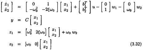
Consider a real modal state-space model of a flexible plant. When focusing on a single flexible mode with damping ratio £ and natural frequency ш, one obtains:

Where the bf’s are row vectors, while C is a matrix. An uncertainty in the natural frequency w is introduced as:

Подпись: (3.29)u> — (1 + 5)(Jo

SIMPLE METHOD FOR PHYSICAL MODELSwhere ujq denotes the nominal value and 6 the relative variation. The state-space model above becomes:

SIMPLE METHOD FOR PHYSICAL MODELS

Fictitious input (vector) w and output (vector) z are introduced:

SIMPLE METHOD FOR PHYSICAL MODELS

Let Д = Sln. When applying the fictitious feedback w = Az, the issue is to determine the integer n and the state-space matrices В, C, D and ї>2, for which the state-space model of equation (3.31) reduces to the state-space model of equation (3.30).

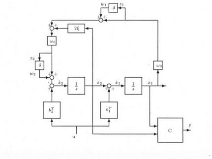
Figure 3.5. A physical method for introducing uncertainties in a plant model

This problem can be solved in an analytical way. However, an al­ternative very simple solution uses the physical representation of the state-space model (3.30): see Figure 3.5. The idea is to compute the augmented plant H(s) of Figure 3.5, with inputs u, w and w2 and out­puts y z and z2 (and 5 = 0):

SIMPLE METHOD FOR PHYSICAL MODELS

Let Д = diag( 5, 5 ) . The LFT transfer Hi ( H( s) , Д ) coincides with the transfer (3.30) between input u and output y, and this LFT realization is minimal.

SIMPLE METHOD FOR PHYSICAL MODELS

CHENG AND DE MOOR’S METHOD

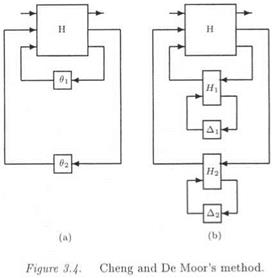
As said at the beginning of this chapter, an LFT model can be com­puted when the coefficients of the state space model or transfer matrix are most generally rational functions of the parametric uncertainties. The aim of this subsection is to illustrate this by detailing the method by (Cheng and DeMoor, 1994). This technique uses the fact that an interconnection of LFTs is also an LFT. The idea is to realize separately the linear and nonlinear parts of the model.

Let:

x = A(6)x + B(S)u

у = C(S)x + D(5)u (3.21)

CHENG AND DE MOOR’S METHOD

where the coefficients of the matrices A(<5), B(6), C(8) and D(6) are rational functions of the vector 2 of parametric uncertainties. As in the previous section, the above equations can be rewritten as:

р(8) = ро + ‘£ъш

Подпись:

Подпись: where:
CHENG AND DE MOOR’S METHOD

3=1

CHENG AND DE MOOR’S METHOD

where the /#)’* are scalar rational functions of <5. Consider then the fictitious matrix Р(в):

CHENG AND DE MOOR’S METHOD

Using the method of the previous section, it is easy to realize the matrix m as an LFT F (Rt. 0)} where 0 — cHag^Ojlqf and ({j is the rank of matrix

On the other hand, the scalar rational functions fj{8) are realized as elementary LFTs fj(S) — Fi(Hj, Aj), where Aj = diag( SiIqid) is a di­agonal matrix containing possibly repeated real scalars Si (the number qitj of repetitions of the scalar Si in the model perturbation Aj obvi­ously depends on the structure of the scalar rational function fj(S)). To

CHENG AND DE MOOR’S METHOD

illustrate this in a simple way, let:

CHENG AND DE MOOR’S METHOD

and let Ді = 8. Then:

Any rational first order function can thus be realized under the above LFT form.

Remember now that 9j = fj{8), so that an LFT model of the mat­rix P(8) can be computed as the interconnection of the LFT P(6) = F[(H, 0) with elementary LFTs 9j = fj{8) = Fi(Hj, Aj): see the ex­ample of Figure 3.4, in which two scalar rational functions 6 = f(8) and 02 = f2(8) are considered.

The method is thus conceptually simple, even if a large number of elementary LFTs is possibly to be handled in practice. The approach moreover proves that an LFT model can be obtained in the very general case of coefficients of the state space model or of the transfer matrix, which are rational functions of the parametric uncertainties. Neverthe­less, the method does not give (at least a priori) the minimal size LFT model.

THE GENERAL CASE

3.1 INTERCONNECTION OF LFTS • It is first illustrated that the interconnection of various elementary LFTs is also an LFT. Consider the example of Figure 3.2, which rep­resents the way a complete LFT model of the transport aircraft will be obtained in the next chapter. Remember that a complete aircraft model is obtained by adding at the physical outputs the rigid and flexible mod­els (see chapter 2).

Подпись: actuators THE GENERAL CASE

An LFT model was separately obtained for both rigid and flexible models. This means that the rigid LFT model contains the physical in­puts й and outputs yr and additional inputs wi and outputs z%, with the fictitious feedback wi = AZ (see Figure 3.2). In the same way, the flexible LFT model contains the physical inputs и and outputs у/ and additional inputs W2 and outputs Z2, with the fictitious feedback W2 = Д2^2- The complete LFT model of the aircraft, у = Fi(H(s),A)u, is computed as an interconnection of the two above LFTs. The augmen­ted model perturbation is Д = diag(Aі, Д2), while H(s) is the transfer matrix between inputs u, w, W2 and outputs y, и i and Z2-

ir*

Figure 3.2. The interconnection of LFTs is an LFT

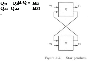
• The star product S(Q, M) of Q and M is defined in Figure 3.3 as a specific interconnection of two LFTs. It corresponds to the transfer
between inputs и і, и 2 and outputs уі, уї-

Подпись: S(Q,M) = where Q and M are partitioned as:Ft(Q, Mn) Qu{I – M11Q22) 1-^12}o1q

THE GENERAL CASE

m21(i-q22mu)-1Q2i fu(

AFFINE UNCERTAINTIES

Consider the case of parametric uncertainties Si entering in an affine way the state-space model of the plant:

N N

x = (Ao + Ai8i)x + (Bo + Bi8j)u

i=1 t=l

N N

У = (Со + £едя + (В0 + £Вгй)и (3-3)

i=l i=l

AFFINE UNCERTAINTIES

with dim x = n, dim n — — and dim у — —. The above equations can be rewritten as:

AFFINE UNCERTAINTIES

where (j €E [0, N]):

AFFINE UNCERTAINTIES

The idea is to introduce additional fictitious inputs and outputs w and z, so that the uncertainties <5г appear as an internal feedback w = Az, with Д = diag(5ilqi). To this aim, the following augmented model is introduced:

AFFINE UNCERTAINTIES

Matrices (^4о,-Bo, Co, Do) represent the nominal plant model (i. e. the one corresponding to 5 = 0). The issue is to look for matrices В’, C, Dyii A2i, £>22 and for a structured model perturbation Д satisfying (V «5 Є Rn):

The LFT Fi(Q, A) can be written as:

Подпись:Fi(Q, A) = Qn + QnA(I – Q22A)~1Q2i

AFFINE UNCERTAINTIES

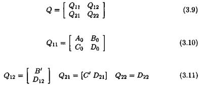
with:

AFFINE UNCERTAINTIES

Because of the affinity of the equations as a function of the parameters Su Q22 = 0. Matrices Q21 et Q12 must satisfy:

AFFINE UNCERTAINTIES

Let q, the rank of matrix =, which can be factorized as:

with P= q Pn’ =* , Pi q Pnq ’ =* , Pi q Pn• =* and Pi P Pn= ’ =• . As a con­

sequence:

AFFINE UNCERTAINTIES

It is then deduced that:

With reference to the above equation and to relations (3.11) and (3.12), one obtains by identifying each term:

B’ = [h… LN]

D2 = [Wi… WN]

C = [i? i… Rn]T

D21 = [Z … Zn]t

-D’22 = 0

Д = diag(dilqi) (3.16)

The issue is finally to come back to an input/output framework. Equa­tion (3.3) corresponds to a transfer matrix у = G(s, S)u, where as equa­tion (3.6) corresponds to the augmented transfer matrix:

As expected, when using the feedback = = P z, one obtains:

y = G(s,6)u = Ft(H(s),A)u (3.18)

REALIZATION OF UNCERTAIN SYSTEMS UNDER AN LFT FORM

1. INTRODUCTION

The issue is to transform a closed loop subject to model uncertainties (parametric uncertainties and neglected dynamics) into the standard in­terconnection structure M ( s ) — Д Д ) of Figure 3.1. As illustrated in chapter 1, the key issue is to take into account the parametric uncertain­ties entering the open loop plant model: the uncertain transfer matrix G(s, 6) (where S is a vector of uncertain parameters) is to be transformed into an LFT Fi(H(s), Д), where Д = diag(SiIqi) is a real model perturb­ation.

REALIZATION OF UNCERTAIN SYSTEMS UNDER AN LFT FORM

We first consider the simple case of parametric uncertainties entering in an affine way the state-space model of the plant. A simple method (Morton and McAfoos, 1985; Morton, 1985) is indeed available for this special case, which is often encountered in practice. The general prob­lem is then considered in the third section. It is proved in e. g. (Belcastro and Chang, 1992; Lambrechts et al., 1993; Cheng and DeMoor, 1994)
that an LFT model can be obtained in the following very general case: the coefficients of the state space model or transfer matrix are rational functions of the parametric uncertainties. This covers most of the engin­eering examples. The problem is however the potential non minimality of the computed LFT model: see also (Font, 1995).

REALIZATION OF UNCERTAIN SYSTEMS UNDER AN LFT FORM

This is an important problem from a practical point of view. Consider a simple example with two parametric uncertainties <5i and S?. Assume that an LFT model of the transfer matrix G ( s. 6 ) was computed with:

The LFT model is non minimal if an other LFT model could be found, which equivalently models G(s, 6) with a simpler structure for the real model perturbation, e. g. :

Подпись: (3.2)Д = diag(Si, S2)

The model perturbation (3.2) is more attractive than the one of equation

(3.1) for two reasons. When applying the у tools to the interconnection structure M – A, the computational amount is an increasing function of the complexity of the model perturbation G. As a second reason, when computing e. g. the classical у upper bound of (Fan et al., 1991), the result is a priori more conservative with the model perturbation (3.1). It is indeed observed in practice that the more repeated a scalar, the more conservative the у upper bound (Packard and Doyle, 1988). Neverthe­less, note that an LFT model can be reduced a posteriori with various heuristic methods (Beck et al., 1996).

As a final point, a simple method is proposed for transforming an un­certain physical plant model into an LFT form (section 4.). The next chapter will apply this method, as well as the method by (Morton and McAfoos, 1985; Morton, 1985), to the two aeronautical examples.

. THE TELESCOPE MOCK-UP

u>i{rd/s)

di

u>i(rd/s)

di

1

288

0.006

11

1162

0.004

2

536

0.098

12

1175

0.015

3

558

0.038

13

1200

0.005

4

647

0.003

14

1309

0.006

5

714

0.002

15

1329

0.007

6

799

0.002

16

1364

0.008

7

870

0.010

17

1418

0.009

8

901

0.011

18

1447

0.005

9

933

0.011

19

1563

0.012

10

943

0.013

20

1563

0.005

Figure 2.6. Flexible modes.

This mock-up, which is used to study high accuracy pointing systems, is composed of a two axis gimbal system mounted on Bendix flexural

pivots. We more precisely focus on the elevation axis of the telescope. A 40th order identified model is available. The frequency response of the transfer function g(s), between the commanded torque and the acceler­ation measured on the telescope main body, is depicted in Figure 2.5. The characteristics of the 20 poorly damped modes of the model are presented in Figure 2.6.

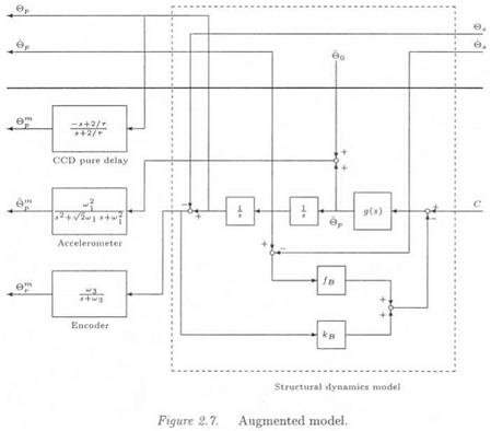
The main control design objective is the rejection of supporting vehicle disturbances. To achieve this goal, an augmented model is built on the basis of the identified model g( s) . As usually in i# or #2 synthesis, the control design objective is expressed under the standard form of Fig­ure 2.7, as the minimization of the transfer from the disturbances (pos­ition and velocity of the supporting vehicle 6S and 6S) to the controlled outputs (position and velocity of the telescope 9P and 9P).

. THE TELESCOPE MOCK-UP

C represents the control input. Three measurements are available, which add sensor dynamics to the system : 0™, в™ (inertial elevation angle and angular acceleration) and 9™ ss 0P — 9S (relative elevation angle). Bendix pivots are represented by feedbacks of stiffness and fric­tion кв and /в■ The order of the augmented system is equal to /V 6, where N is the order of g{s) (40 if the full order identified model is used) and 6 represents the 2 Bendix states and the 4 sensor states.

See (Madelaine and Alazard, 1998; Alazard et al., 1996; Madelaine, 1998) for the design of the control law. Note simply that the order of the #2 controller is 13, so that when applying this controller to the 46th full order plant model of Figure 2.7, a 59th closed loop flexible system is obtained. In this example, the issue will be to analyze the robust­ness properties of this #2 controller with respect to uncertainties in the natural frequencies of the bending modes (see chapter 10).

APPLICATION

The choice of the compensators is not detailed, the interested reader is referred to (Ferreres and M’Saad, 1996) for a related work. The values of the pre – and post-compensators are:

APPLICATION

APPLICATION

where 1/r = 120 rad/s, k — 1.5, lji = 5 rad/s, u>2 = 0.5 rad/s and k2 = 0.40. The design model is the linearized missile model at a = 3 deg with the second order actuator.

DESIGN OF THE Нж AUTOPILOT

1.1.1 PRINCIPLE OF LOOP SHAPING Нж CONTROL

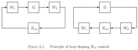
In the case of a SISO system, the very classical Bode method shapes the magnitude and phase ofthe open loop frequency response K(jut)G(ju>), where K(s) and G(s) respectively represent the controller and plant model. As an extension to the case of a MIMO plant 0(5), the sin­gular values of the open loop transfer К (jut ) G )К ) or G (juj ) К (К ( can be shaped (McFarlane and Glover, 1990; McFarlane and Glover, 1992). To this aim, pre – and post-compensators IEi(s) and W2G) are added at the plant inputs and outputs. These transfer matrices Wi(s) are chosen so that the singular values сг; ( К Gg)G(К) К )К) ) reflect the design objectives.

DESIGN OF THE Нж AUTOPILOT

A specific robust stabilization procedure is then applied to the aug­mented plant W2GW1 (see Figure 2.4). A controller Ко is obtained, which stabilizes the augmented plant. The final controller is K(s) = ITrx(s)-K’oo(s)W2(s). Note that the above robust stabilization procedure presents special properties, since it tries as much as possible to keep the desired open loop shaping while enforcing a stability closed loop con­straint.