Category NEW DESIGN CONCEPTS FOR HIGH SPEED AIR TRANSPORT

Parameterized Curves and Surfaces

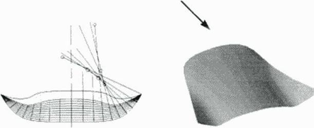
The geometry tool explained here has been developed in the years shortly before interactive graphic workstations became available, originally for input with data lists but increasingly laid out for interactive usage in the windows environment of the workstation. The list input still is the basic option and data for such usage will be presented here for explanation. Focusing on surface modelling of aerodynamically efficient aircraft components, we realize that the goal of shape generation requires much control over contour quality like slopes and curvature, while structural constraints require also comers, flat parts and other compromises against otherwise idealized shapes. When familiarity is gained with a set of simple analytic functions and the possibility is used to occasionally extend the existing collection of ID functions, ground is laid to compose these functions suitably to yield complex 2D curves and finally surfaces in 3D space. This way we intend to develop tools to define data for airframe components with a nearly unlimited variety within conventional, new and exotic configurations. A bncf illustration of the principle to start
with ID functions, define curses in 2D planes and vary them in 3D space to create surfaces is given:

GEOMETRY GENERATOR FOR CFD AND APPLIED AERODYNAMICS

H. Sobleciky

DLR German Aerospace Research Establishment, Gottingen. Germany

9.1 Introduction

This chapter is intended to combine the knowledge bases of applied geometry with those of hy­drodynamics and aerodynamics, including die modest additions presented in the two previous book chapters focusing on the interaction between compressible flow with shock waves and flow boundary conditions The need to have flexible tools for effectively influencing the phenomena occurring in high speed flow calls for development of fast and flexible softw are to create shapes in a way to have easy access to the crucial shape-generating parameters controlling these flow- phenomena. and at the same time observe the constraints given by structural and other practical limitations.

Renewed interest in Supersonic Civil Transport (SCTi or High Speed Civil Transport (HSCT) calls for extensive computational simulation of nearly every aspect of design and devel­opment in the whole system. CAD methods arc available presently for many applications in the design phase. Nevertheless, work in early aerodynamic design lacks computational tools which enable the engineer to perform quick comparative calculations with gradually varying configu­rations or their components. To perform aerodynamic optimiiation. surface modelling is needed which allows parametric variations of wing sections, planforms. leading and trailing edges, camber, twist and control surfaces, to mention only the wing. The same is true for fuselage, empennage, engines and integration of these components. This can be supported in principle by – modem Computer Aided Design (CAD) methods, but data preprocessing for numerical flow simulation (CFD) calls for more directly coupled software which should be handled imerac –

lively by the designer observing computational results quickly ami thus enabling him to develop his own intuition for the relative importance of the several used and varied shape parameters The requirements of transonic aerodynamics for transport aircraft in the high subsonic flight regime as well as more recent activities in generic hypersomos for aerospace plane design con­cepts have enhanced previous activities (113], 1114] in the development of dedicated geometry generation (115]. Based on experience with the definition of test cases for transonic aerodynam­ics [ 116) and with fast optimization tools for hypersonic configurations outlined in the previous chapter, as well as taking into account new developments in interactive graphics, some fast and efficient software tools for aerodynamic shape design are already operational or under develop­ment. The concept seems well suited for application to various design tasks in high speed aero­dynamics and fluid mechanics of SCT aircraft projects, especially with options to select suitable parameters for an application of optimization strategies which will be presented in following book chapters.

It is the author’s intention to illustrate the options of the proposed method for a system­atical development of some of the required technologies for high speed aircraft design, at least those needed in aerodynamics, some for aeroelastics and for aeroacoustics. Computational sim­ulations will have an ever increasing share in technology development though experiments arc still needed; wind tunnel models arc to be created by CAD systems for which the geometry gen­erator as a preprocessor must provide data of exactly the same accuracy as for CFD.

Much use is made of graphic illustrations in this chapter which is natural for this topic and which may be more useful than much text. A powerful interactive fluid mechanics visuali­zation software system (117] greatly adds to an efficient use of shape design methods struc­tured and unstructured CFD grids, shaded solid surfaces and isofringes depicting flow variables distribution results arc displayed on a graphic workstation screen and for a few examples in the following pages.

Waveriders with Arbitrary Shock Waves

The OC wavender design method has proven to be extremely useful for practical design tasks so far. but further generalizations seem worthwhile for curved bow shock waves: a replacement of conical flow by an axisymmetnc base solution resulting from the 2D inverse method of charac­teristics may give waveriders with better volumetric efficiency because the convex shock shapes to be prescribed as illustrated in Figure 48 (c) result rather from blunter ogive – shaped forcbodies than from cones.

Inverse solution to the 3D Euler equations with the SCIEMAP code

A 3D arbitrary but analytically controlled oblique shock wave requires an even more general approach: a marching procedure toward the contour surface to be found has to be applied. An inverse solution to the Euler equations results from such an approach. After some first results 1100] conlirming the concept, a numerically more advanced treatment taking into account the *caveats’ postulated in a previous paragraph led to an inverse Euler solver ‘SCI­EMAP – Supersonic Cross-stream Inverse Euler MArching Program’ (III].

Figure 52 SCIEMAP – designed Wave rider with variable strength shock wave; CFD in viscid analysts (code: F3D), verification of the shock wave geometry.

The 5 equations of motion (continuity, energy and 3 momentum equations) plus 10 equations for the expansion of the 3D flow gradients on the post-shock wave front w ith its given geometry and 5 primitive variables resulting from the Rankinc – Hugomot oblique shock rela­tions give a system of equations for the 3D gradient vector of the primitive variables. This is suitably used in a local domain marching grid observing the constraints and limitations given by the caveats. Some promising configuration studies have been carried out (111]. (112|; an exam­ple is illustrated in Figure 52. This method has the potential to be applied to other problems

where an inverse solution to the compressible steady flow Euler equations seems promising.

8.2 Conclusion

Two inverse design methods have been presented here to obtain supersonic and hypersonic wa- vender shapes with geometnes more general than available from previously used known flow fields: The Osculating Cones (OC) concept is realized in the WIPAR computer code and the in­verse integration of the 3D Euler equations from prescribed shock surfaces is performed with the SC1EMAP code.

In the first approach use is made of axisymmctric flows to construct flows with more general shock wave shapes (slope surfaces), but still constant shock strength. The WIPAR soft­ware is an interactive computer program for graphic workstations and allows for a flexible parameterized input of the basic aerodynamic and geometric parameters of wavender wings, like the design Mach number, shock angle and planform geometry. Applications have been car­ried out adding extensions for viscous flow and thermal load. Case studies making use of the OC concept serve as test cases for optimization strategics and propulsion integration.

In the inverse Euler design approach, cross-marching is an exact method of characteris­tics for inverse 2D and axisymmctric calculations but mathematically ill-posed in general 3D flow modelling; nevertheless it is used successfully to create wavender shapes with more gen­eral shock shapes of varying strength. The new numerical marching technique makes use of some features of characteristic cross-marching, results were obtained confirming shapes known from other methods and also completely new with improved volumetric efficiency’.

Comparing both inverse methods, each approach has its merit: While SCIEMAP may he used for more general fluid mechanic modelling requinng solution to an inverse problem and the wavenders created may have better volumetric efficiency, the use of the WIPAR software enables the designer to comfortably create shapes containing various geometric details similar to a configuration generator for general purpose, as being outlined in the next book chapter.

Design and optimization software based on the OC method

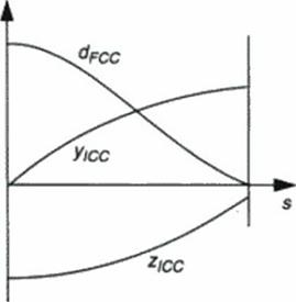
The OC method has proven to be a very flexible design tool requiring only a few input parameters for obtaining a wide vancty of configurations w ith supersonic leading edges, plus (and that’s the attractive feature) it also gives results for the complete flow field and lift and wave drag of the configuration. In this situation a flexible definition of the 3 functions (Уїсс* *юс – an<* °f ICC arc length s. see Figure 49) is most important for rapid prc-dcsign and optimisation studies. The first application software illustrated below combines the OC method with geometry input used in a more general configuration generator outlined in the next book chapter. The latter makes possible a definition of curves with piecewise analytic structure and control of first to third derivatives which arc needed for the calculation of local cone axes as depicted in Figure 50.

The WIPAR interactive code

A versatile computational tool, the ‘Wavender Interactive Parameter Adjustment Rou­tine ♦ WIPAR” – (103). {104) was written for usage on graphic workstations, allowing for a fast and educational display of the resulting configurations and aerodynamic coefficients at design conditions. Some features of this powerful software are illustrated in Figure 51: The windows environment with various adjustment sliders, quick look diagrams and key results displayed make this computer code a suitable baseline for a hypersonic configuration design expert sys­tem. Various configuration examples have been studied and some have been manufactured for experimental investigation in wind tunnels Experiments in the subsonic Mach number regime have been carried out for a wavender similar to the configuration depicted in Figure 51. which was optimized for Mach 4. Results confirm conclusions that wavcridcrs based on the OC con­cept may also have quite favorable aerodynamic characteristics in the low speed regime [ 105).

Aerospace vehicle and SCT aircraft optimization studies based on WIPAR

The WIPAR software is used for an implementation in practical aircraft and aerospace vehicle design systems. For improved modelling of viscous flows and thermal loads, refined methods for boundary layer and heat transfer have been developed and coupled with the design program (106). (107).

With the main thrust of wavender applications so far being directed toward aerospace vehicle operation at hypersonic Mach numbers, an alternative use is proposed for the layout of aircraft wings for high speed transport at even the lower supersonic Mach numbers 1108]. Here the high Mach number design cases arc found to have remarkably good L/D ratios and are there­fore investigated further, namely regarding the influence of sweep on the occurrence of bound­ary layer instabilities and the potential of such wings for laminar flow control. Flexibility in creating configurations for missions in the supersonic as well as in the hypersonic flight regime makes the wavender concept attractive for a vanety of high speed transport concepts. Investiga­tions on a series of configurations derived from WIPAR generated shapes have already been studied for TSTO missions using a multidisciplinary aircraft design program 1109).

Propulsion integration on OC nave riders

The flow field including streamlines between the lower surface of a wavender and the oblique shock is readily available for OC waveriden at design conditions. This may be used for adding stream-aligned surfaces like the propulsion casing, and furthermore, flow conditions at the inlet capture curve ("ICC*) may be input for internal flow simulation of the propulsion unit. This way generic wavender configurations with a flexibility obtained using the OC concept are ideal input for design considerations beyond purely aerodynamic aspects: Multidisciplinary design optimization of realistic vehicles will require a synchronized development of aerody­namic. structural, acroclastic and propulsive components, among many other considerations. Some aspects are already studied in the design of wavcridcrs with integrated propulsion includ­ing inlets and nozzles (110|.

Osculating Cones (OC) Waveriders

8.3.1 Generalization of the conical flow w a vender

Л suitable selection of strcamsurfaccs from a given analytical or numerical solution for a 3D su­personic flow with a shock system may define the solid boundary of an obstacle in this flow, with the shock waves mthe flow generated by this obstacle. This is the basic design principle of the waverider, which is basically a simple supersonic generic aircraft. Renewed interest in high Mach number supersonic and hypertonic transport vehicle design revived the classical wavender principle using wedge and cone flows to carve out a multiplicity of shapes, suitably parameter­ized and shapes selected by optimization strategies (102). This is made possible in a fast and ef­ficient way because the used flow solution is known and so arc pressures along the contour, integrated to lift and drag at inviscid flow design conditions very’ easily. Furthermore, known streamlines allow for a quasi – 2D boundary layer computation, subsequent shape correction and viscous drag computation. Viscous flow optimized waveriders are therefore the starting point to a refined configuration definition for high speed transport aircraft

Combining plane and axisymmetric flow: Slope surface shock waves

Wavender aircraft have supersonic leading edges of a completely integrated wing • body configuration. Planar 2D flows arc suitable for lifting w ings with sufficient span but suffer from low volumetric efficiency. Conical flows give better volume but have a small aspect ratio resulting in bad low speed performance. A compromise is a higher order approximation to exact model flows by a spanwise van at ion of the local cone radius it is an application of the above

mentioned validity of locally axi symmetric flow. Figure 49 illustrates the geometric definition of a conical or generalized shock segment bounded by the waverider inlet capture curve (ICC) coordinates and the leading edge which serves as a flow capture curve (FCC). This definition of a shock wave patch with given obliquity angle P includes planar, conical and slope surface shock waves with constant strength. The latter are envelopes of a single cone sliding along the given leading edge (FCC) in 3D space, and the idea to approximate the resulting flow field behind such shock waves by the local tangent cone flow meridional (osculating) plane results in relatively high accuracy of this straightforward definition of the lower surface along with us pressure distribution.

As in previous waverider work, the upper surface may be a free stream surface or has to be designed for additional lift by convex contouring for flow expansion. In the following illustrations some examples designed with software based in this principle is shown. Fast design codes based on this method have been developed by various authors. Extensions fix refined vis­cous flow modelling and for incorporating propulsive devices have been developed.

N

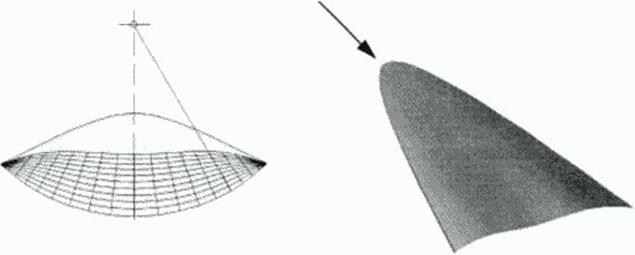
Figure 49 Defining the bow wave of a conical flow* waverider: Inlet capture curve (ICC) and leading edge or flow capture curve (FCC). Generalization* for OC waverider* if ICC is not a circle, shock segment is a slope surface, shock angle is P

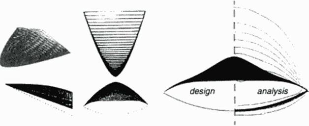
Figure 50 Waveridere generated from bow shocks (shock angle (5 ■ 18°) in supersonic freestream of M. * 4. Cone-derived (above) and OC configuration

Axisymmetric Hows with given shock waves

Examples showing the possibilities to compute axisymmetric flow elements resulting from given shock waves arc given in (101}. The well known flow past a circular cone in supersonic flow is verified as well as generalizations for curved shocks w ith varying strength followed by rotational flow. Figure 5 illustrates the solution for a cone flow and for the flow past a curved axisymmetric shock wave element, as it occurs in the flow past an ogive body nose. The character! sties gnd depicts the full solution extending beyond the contour streamline: a limiting cone is found with no solution appearing near the cone axis.

This fast numerical method of characteristics is an inverse Euler solver to design 2D and axisymmetric flows with given shock waves. The flow past a circular cone has been described by Taylor and Maccoll. its conicity reduces this special case of axisymmetric flow to solving one ordinary differential equation This will be used in the following description of practical design methods by locally applying conical flow as an ‘osculating flow pattern’ in more general 3D boundary conditions. Curved shocks will allow for an even wider variety of using an axisymmetric flow element for 3D flow design.

Construction of Flows with Oblique Shocks

This work is an approach to compute supersonic flowficld models which arc mathematically simulating a part of the inviscid flow past an aerodynamic configuration. For wavenders, these flows will be bounded by a shock wave, a stream surface defining a solid body contour, and an exit surface. Such boundanes allow to place this model within given supersonic upstream flow conditions, connected along the shock by the Rankine – Hugoniot relations

8.2.1 Crass – marching in supersonic flow

An earlier, similar approach, as described tn the previous book chapter, was aimed at connecting a local supersonic flow field with surrounding subsonic flow along a prescribed sonic line. This procedure was used to model transonic flows with applications in supercritical w ing design This process was first earned out as a linear method of characteristics, it is equivalent to marching in a direction normal to the flow (“cross – marching”), thus allowing for a start at initial conditions compatible with embedded supersonic flow domains.

Locally axisymmetric flow

Within 2D inviscid supersonic flow, a local linearization of the basic equation for a velocity potential Ф gives the wave equation

(68)

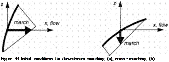
where x is the direction of the local flow vector. We realize that both x and z are time-

Подпись: Figure 44 Initial conditions for downstream marching (a), cross • marching (b)

like directions, a marching in the flow direction or normal to it are mathematically equivalent, their choice determined only by formulation of the initial conditions, sec Figure 44.

Axisymraetric flows axe a special case of 3D flows, but their computation may also be earned out in a 2D meridional plane by the method of characteristics. It can be shown that the axisymmctric model equation for linear supersonic flow

(69)

can be used to second order approximate locally a 3D flow element which is a solution to the general 3D flow equation

(70)

Location of the axis of this osculating axisymmetnc flow depends on local flow curva­ture and velocity gradient. This can be used to develop a 3D method of characteristics, which has locally 2D properties and therefore reduces perturbation amplification in a numerical cross * marching approach

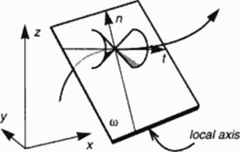
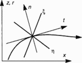
Figure 45 illustrates 2D flow and the possibility to locally approximate 3D flow by an axisymmetnc flow model.

Figure 45 Two • and three-dimensional flow. Normal and tangential vectors n. t.

Osculating plane (i) to streamline as a meridional plane of osculating axisymmetric flow, characteristic lines x, h in 2D flow, Mach conoids in 3D flow.

The abovcmentioned idea of cross – inarching is intended to familiarize the reader with a strategy of numerically integratung flow model equations from initial data determined solely by unperturbed upstream flow and a geometrically defined oblique shock wave. The flow held behind this shock has to be evaluated by using the method of characteristics, for irrotational flow equivalent to a potential flow solver, for rotational flow resulting from an arbitrarily curved shock wave equivalent to an Euler solver. Boundaries given for and resulting from characteris­tics calculation in the following will be explained for the simple flow past a wedge, because using a marching code later will require to keep in mind regions of dependence if a numerical scheme should work properly.

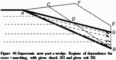
The flow past a wedge is sketched in Figure 46 to show how cross – marching will be used to obtain the flow field solution in part or in whole. Let supersonic flow be deflected by a wedge contour AG. A shock AB forms end bends the streamlines within triangle AGB confor­mal to the wedge anglcWc ask now for the inverse computational approach to find the flow and the contour behind the given portion AB of the shock wave. Characteristics resulting from cross – marching will define a triangular region of dependence ABC. which includes a non-physical part of the solution beyond the contour AD. which results from flow field integration within ABC. On the other hand. a part DBG of the physical solution is not available with initial data given only along AB. Data need to be given also along a portion BE of the exit, with results along CB available this defines the solution within the polygon CBEF. Evaluation will define the streamline continuation beyond D toward an exit value at Gsituated on BE or EF. depending on the choice of E. For high supersonic Mach numbers, contour length AD may be only a frac­tion of the continuation DG.

Подпись: Figure 46 Supersonic now past a wedge: Regions of dependence for cross • marching, with given shock ЛН and given exit BE.

For curved shock waves prescribed, we have to expect rotational post-shock flow resulting from the computation. The contour streamline is another characteristic now. cross • marching requires avoiding contradictory initial data along AB and BE, if both domains have to be solved. Furthermore, data for entropy or vorticity distribution arc not defined beyond the con­tour (to be computed!, which may pose a problem for cross • marching.
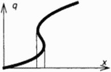
Another feature of cross – marching with the method of characteristics is the possibility of limit lines occurring in the computed flow. A multivalued solution may he found because the marching is essentially carried out in a hodograph plane: i. e. a variable of slate, for instance the velocity q. is the independent variable to march along, w hile coordinates x of physical space arc resulting, see Figure 47. Such a solution cannot be obtained by marching in physical space: the marching direction would have to be reversed to pick up a continuous solution q(x). Occurrence of a limit line or surface alerts us that the given shock wave is not compatible with a smooth flow downstream of it. the initial data should be changed.

Подпись:Representative variable of state q as a function of representative space coordinate x: multivalued solution if limit lines (surfaces) occur.

We draw some conclusions from this outline of models to be simulated numerically and used for practical design aerodynamics:

Caveats for a numerical cross ■ marching integration concept

1. Given oblique shock waves require cross – marching to obtain a contour compatible with initial conditions.

2. Cross – marching in 2D plane or axisymmetnc flow is effectively carried out by wrll – posed hodograph (inverse) methods of characteristics.

3. 3D flows may be approximated locally by (osculating) axisymmetnc flow.

4. Extent of contours designed with cross – marching may be small compared to extent of the given shock wave in high Mach number supersonic flow.

5. Rotational flow constrains region of dependence to physical flow bounded by designed contour.

6. Occurence of limit surfaces requires initial data modification; inverse marching allows to pick up limit lines, direct space marching results in infinite gradients.

Figure 48 Mach number М» = 2. circular cone flow integration and flow element past a curved shock wave. Given shock cone angle 45* (a), resulting solid cone angle 27.32° and analytical continuation toward limit cone (18.5°) within solid cone boundary. Isomach fringes of conical (b) and curved shock (c) flow field.

CONFIGURATIONS WITH SPECIFIED SHOCK WAVES

H. Sobitczky

DLR German Aerospace Research Establishment, Gottingen. Germany

8.1 Introduction

Supersonic flow elements arc valuable components for the development of new aerodynamic de­sign concepts for efficient high speed flight vehicles Among these elements, flows with oblique shocks may be used to shape socalled waveriders, which are almost classical cases where the component may already form a high lift-over-drag (UD) configuration (96). (97). In the past dec­ades. the mathematical models of plane or «asymmetric supersonic flow fields with shocks have been used to create a number of simple lest cases for experimental investigation, long before nu­merical flow analysis methods and large computers were available

Today wc have various invisetd and viscous CFD analysis methods operational to investigate the aerodynamic performance of airfoils, wings and 3D configurations in design and off-design conditions. Waveriders arc ideal test cases for numerical methods simulating inviscid compressible flow: Special known shock patterns occur on relatively simple geometries at design conditions. In this situation we may flunk about creating more general and perhaps more efficient waveriders by new design methods, mature CFD analysis will verify the predicted inviscid flows and help to analyze design and off-design conditions performance, allowing for substantial reductions in systematic wmdtunnel testing.

Inverse aerodynamic design is an approach to obtain configuration elements compati­ble with certain desired performance characteristics In supersonic and hypersonic flow, the shock wave formed by the lifting body at the leading edge is carrying much of the information about lift wave drag and noise, which are key issues in applied supersonic aerodynamics. It seems a challenging task therefore to invert the design problem by controlling the bow shock

wave and find compatible body surfaces. Since the 1960’s wavender configurations arc con­structed from simple known plane or axisymmetric flow fields with oblique shocks, suitably cut by stream surfaces to provide special delta wings with sharp leading edges.

In this chapter wavender flows arc generated from given shock wave geometries. In the past years since Nonwetlcr’s first caret wing wavchders (98), plane 2D and axisymmetric conical flows have been used for the generation of lifting wings in supersonic flow, with the detailed іnviscid flow structure coming as a result with the geometric shape. In the recent years a revived interest (99) in these wavender* has emerged, to use them as baseline configurations with known aerodynamic performance at idealized design conditions, for further development and optimization using CFD as well as refined experimental techniques. Two new concepts (100] were presented for this purpose: ‘Osculating Cones* and ‘Inverse Euler Marching’ tech­niques, to obtain more general wavender geometnes than derived previously from plane or con­ical generating flows These concepts and applied work based on them are reported here in the following.

Practical design methods for local shape modifications

Dunng recent years a number of computational methods for designing 2D airfoils and 3D w ings in the transonic regime have been developed. Among them arc inverse methods, with the task to find airfoil or wing shapes for a prescribed pressure distribution. These latter methods are re­viewed in chapter 10 of this book. The aim in the present chapter is only to illustrate some rela­tions between gasdynamic properties of compressible flow and some practical consequences for 2D and 3D surface geometry quality.

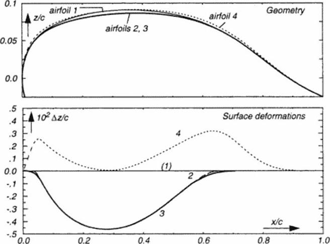
In practical aerodynamics frequently a given configuration and its components may be modified only locally because of structural and other constraints. The FG design method is a practical tool if small local changes are allowed on the suction surface of a lifting wing: thick­ness distribution of a typical transport aircraft wing section may be reduced along a limited por­tion along chord less than half a percent to obtain improved aerodynamic efficiency up to 15 percent! Improvements also may he obtained for sections with local thickness added to the given geometry. To illustrate this, a series of simple design modifications to the thick airfoil of Figure 40 was carried out and is outlined in Figure 42 and Figure 43:

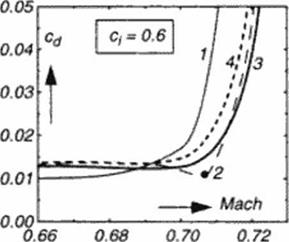
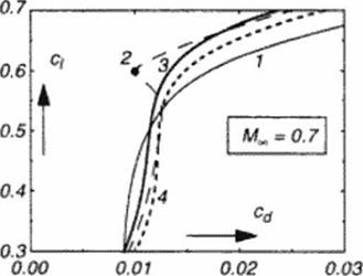
Following a FG computation (Figure 41). the method of characteristics defines a new section geometry on the upper surface ( see the graphics of Figure 40). Contour differences are shown in Figure 42: given (baseline) wing section 1 and resulting section 2 differ by a Az distri­bution. subtracted from the baseline. This Az is smoothly shaped as a bump’ function extending from the some expansion to the recompression location. A comparison of the aerodynamic properties for the baseline (1) and the new airfoil (2) is show n in Figure 43. Drag rise and airfoil polar obtained by CFD analysis (931 are illustrated. Related airfoil geometries with similar effi­ciency improvements may be obtained for mathematical approximations of the whole sub – traded bump or its key features: amplitude and crest curvature. An airfoil ‘3’ is obtained for a bump function with only smoolhened (extended) start and end ramps, resulting in a slight loss in the Lift/Drag (L/D) ratio at design conditions, but with improved off-design performance, reducing ‘drag creep’ at lower Mach numbers. Airfoil ‘4’ is obtained by adding a dual bump (now locally enlarging thickness everywhere along chord), modelling local curvature at x/c – 0.3 to be equivalent to the design modification. The resulting airfoil has still improved aerody­namic efficiency compared to the baseline These latter added bump function may be combined with the concept of more local shape modifications like those used tor influencing viscous inter­action at the shock location (94J.

There arc various ways to calibrate geometrical models like the above used bump func­tions from observ ed phenomena like some surface geometries. The method of characteristics for 2D How is the straightforward exact approach. Analysis of How stream tube displacement requirements lead to even faster methods [951 which are suitable for 3D w ing design.

Figure 42 Upper surface of a thick baseline airfoil (1), shock-free design modification (2), and relaxed geometry variations, for either optimum 17D (3) or maintaining original thickness (4). Vertical coordinate differences Дг relative to baseline airfoil.


Figure 43


Drag rise for constant lift and drag polar at constant Mach number, for above 4 airfoils. Rc = 20 MOL (MSES (931 analysis!

7.2 Conclusion

In this chapter the attempt was made to illustrate some ideas which have been used and still seem to have innovative potential for the development of aerodynamic design tools. A refined analysis of inviscid How phenomena is earned out by mapping into a suitable work space, resulting in mathematical models for local and asymptotic behavior of compressible flows. These models may be used for CFD code validation and also should be i»bserved when prescribing target How conditions in inverse design approaches

Geometric boundary conditions, shock waves and the singularities connected with some llow conditions are shown to be strongly interacting, the know ledge about these phenom­ena may be used for aerodynamic design concepts. These lay ground for an inverse flow con­struction principle with applications to transonic as well as to supersonic flow. Numerical methods may be manipulated and recombined for obtaining airfoils and wings with improved aerodynamic efficiency and concepts for the development of novel flow control techniques could be encouraged by theoretical results.

Supersonic and hypersonic How models derive from these principles, too. and will be used in the following book cliapter for the design of advanced wavenders.

Numerical analysis and models to control gasdynamics result in a more detailed knowledge base about the shaping of flow boundaries, which translates into selecting a set of mathematical deformation functions for the optimization or adaptation of given baseline config­urations. Being guided by the quality of the observed flow phenomena strongly helps to keep the number of control parameters for these functions small, as w ill be demonstrated in book chapter 9

Construction of shock-free transonic flow

Not excluding a future application of the above ‘flow control concept’ we presently arc interest­ed m practical design methods, resulting in local shape modifications accomodating improved aerodynamic performance. The known FG design method combines the above flow control with a second design step replacing the controlled domain by an ideal gas supersonic flow pattern computed as outlined in paragraph 7.3.1. using the inverse method of characteristics or a 3D inarching. The airfoil example illustrated in Figure 40 results from this design computation. A summary of various implementations of the FG to fast potential flow solvers can be found in [89]. Later, the concept was introduced to the Euler equations |90) and Navier Stokes equations 191]. The latter method provides viscous design results based on FG models extending into the boundary layer, also it is a time-accurate computation allowing for unsteady aerodynamic appli­cations.

Some first attempts were taken to apply this design concept also to supersonic flows. As suggested by the shock-free infinite swept wing flow (Figure 40). a 3D supersonic flow design approach analog to the transonic method seems feasible |92J.