Category Theoretical and Applied Aerodynamics

Inviscid Theories of Hypersonic Flows

12.2.1 Hypersonic Potential Flow

In 1946, Tsien [41] derived similarity laws of hypersonic flows, following von Kar – man analysis of transonic similitude. Assuming isentropic, irrotational flow, Tsien used the full nonlinear potential equation with the tangency boundary condition at the solid surface (and not the linearized boundary condition). In the case of two – dimensions, let

Подпись:Подпись: (12.6)Подпись: (12.7)

Подпись: hence,
Подпись: V 2 Aa ~a = -Y - 1 AV
Подпись: (12.4)

dp dp

u = U + , v =

dx dy

The governing equation for the perturbation potential is

u2 d2p uv d2p v2 d2p

a2 dx2 + a2 dx dy + a2 dy2 ^

where

a2 = a2 – 1-1 ((u2 + v2) – U2)

a0 is the undisturbed speed of sound at flow velocity U.

Inviscid Theories of Hypersonic Flows

For hypersonic flow, a0 and dp/dx, p/dy are small compared to U, hence retain­ing terms up to second order, the equation for p becomes

Tsien [41] introduced the coordinate transformation

x y

С —, n =~ (12.9)

c e

where c is the chord and e is the thickness of the airfoil. He justified this choice since for hypersonic flow over a slender body, the variation of fluid velocity due to the presence of the body is limited to a narrow region close to the body.

The corresponding non-dimensional form for y is

a0 c

The lift curves are parabolas and as K ^to, Cl ^ (y + 1)a2.

For M0 < 3, Ackeret theory gives reasonable results where Cl = 4a fj M2 – 1, and the lift curve is a straight line.

For profiles with thickness, Linnell reported the results for diamond airfoils at angle of attack.

For hypersonic flow, the pressure change across a shock of given turning angle is much greater the across an expansion wave of equal turning angle. To avoid a leading edge shock, it is desirable to operate with large angles of attack. Since most of the lift is furnished by the lower surface, it follows that expansion on the lower surface is undesirable and the best profiles have flat lower surfaces.

Regimes of Compressible Flow

For steady, inviscid and adiabatic flows, Bernoulli’s law is

У 2

H = h + — = C (12.1)

where C is constant along a streamline and h = CpT for a perfect gas.

The above relation can be rewritten in terms of the speed of sound (a2 = y RT) as

y 2 + 2 a2 = const = y2ax (12.2)

Y – 1

where ymax is the maximum possible velocity in the fluid (where the absolute temperature is zero) corresponding to the escape velocity when the fluid is expanded to vacuum (Fig. 12.1).

© Springer Science+Business Media Dordrecht 2015 399

J. J. Chattot and M. M. Hafez, Theoretical and Applied Aerodynamics,

DOI 10.1007/978-94-017-9825-9_12

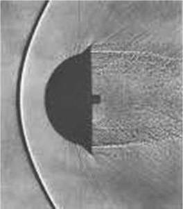
Fig. 12.1 Reentry capsule flow (from history. nasa. gov)


Regimes of Compressible Flow

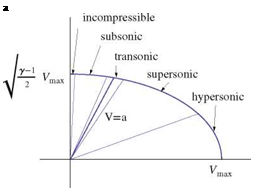
In the following sketch, the different regimes of compressible flow are identified and hence their physical characteristics are discussed, see Fig. 12.2.

(i) For incompressible flow M ^ 1, V ^ a and Aa ^ AV

Notice that

2

V AV + aAa = 0 (12.3)

7 – 1

Подпись: a Fig. 12.2 Regimes of compressible flow

(ii) For subsonic flow M < 1, V, a and |Aa| < IA V |

(iii) For supersonic flow M > 1, V > a and |Aa| > |AV|

(iv) For transonic flow M ~ 1, V ~ a and |Aa| ~ |AV|

(v) For hypersonic flow M > 1, V > a and |Aa| > |A V|

In hypersonic flow, changes in velocity are very small and the variations in Mach number are mainly due to changes in a.

Introduction to Hypersonic Flows

In the previous chapters, compressibility effects are covered, particularly in the transonic regime where the Mach number is close to one. For very high Mach number flows, the situation is different, see Fig. 12.1. The details required for the analysis and design of hypersonic vehicles used in a space program, are both useful and interesting.

The study, in this chapter, is however very limited in its scope. it covers small disturbance theories, hypersonic similitude and similarity parameters as well as blunt body problems (with detached shocks) and theoretical and computational methods for both inviscid and viscous flows at very high velocities.

There are many references available in this field, old and new. For books, see [1-15], for review articles and proceedings, see [16-33] and for numerical methods and solutions, see [34-40]. The purpose here is to give an overview for the reader with emphasis on the main relevant concepts.

. Conclusion

A simple approach to design a small remote control glider or airplane has been presented. It is based on a hierarchy of computer models, that help with the sizing of the wing, using a rapid prototyping code, estimating the take-off velocity with input and best estimate of rolling conditions, and finally, an equilibrium code that analyzes the equilibrium in various phases of the flight, from take-off to cruise and descent and provides the flight envelop in which the airplane is controllable with the tail as a function of the static margin. The design of winglets that contribute to improved efficiency by decreasing the induced drag, is also discussed along with trimming the glider for maximum distance or maximum duration. Lastly, it is shown that with a classic configuration, the wing and tail sizing and the center of gravity location can be found to make the tail a lifting tail at take-off, which is desirable for a heavy lifter airplane.

11.4 Problems

Aerodynamic Center of the Glider

. Conclusion

Derive the formula

from the linear aerodynamic model of Sect. 11.2.

Equilibrium Equation for the Moment

Show that the equilibrium equations can be combined to eliminate CW from the moment equation to give

Xca

Cm о +—- a (CL cos в — CD sin в + CT sin(a + в + т)) cos(a + в) = 0

Iref

Global Aerodynamic Coefficients of a Glider

A glider has the following lift and moment characteristics in terms of the geometric angle of attack a (rd) and the tail setting angle tt (rd):

CL(a, tt) = 5.0a + 0.5tt + 0.5, CM, o(a, tt) = —1.3a — 0.4tt — 0.1

Find the effective aspect ratio AR of the glider (wing+tail) assuming ideal loading and

dCL 2n

d a 1 + 2/AR

Give the definition of the aerodynamic center.

Find the location xa. c./ lref of the aerodynamic center.

Find the location xc. a./ lref of the center of gravity, given a 6 % static margin of stability SM = 6.0.

Derive the expression for the moment about the aerodynamic center as a function of tail setting angle tt, i. e. CM, a.c.(tt).

Find an expression for the moment about the center of gravity CM, c.a.(a, tt). Which condition holds for the moment about the center of gravity at equilibrium? Find the equilibrium condition aeq (tt) and CL, eq (tt) for the glider.

If the glider take-off lift coefficient is CL = 1.5, find the equilibrium angle of attack aeq and corresponding tail setting angle tt.

Explain and sketch under which condition the tail can create positive lift at take-off.

Acknowledgments One of the authors (JJC), acknowledges that part of the material in this chapter was originally published in the International Journal of Aerodynamics, Ref. [4].

References

1. Bertin, J. J., Cummings, R. M.: Aerodynamics for Engineers, 5th edn., pp. 653-656 (2009)

2. Munk, M. M.: The Minimum Induced Drag of Aerofoils. NACA, Report 121 (1921)

3. Chattot, J.-J.: Low speed design and analysis of wing/winglet combinations including viscous effects. J. Aircr. 43(2), 386-389 (2006)

4. Chattot, J.-J.: Glider and airplane design for students. Int. J. Aerodyn. 1(2), 220-240 (2010). http://www. inderscience. com/jhome. php? jcode=ijad

Classical Versus Canard Configurations

A classical configuration consists of the main wing in the front and the tail in the back. In a “canard” configuration, the two lifting elements are reversed (see for example the Wright Brothers’ flyer). The common wisdom is that in a classical configuration, the tail has a negative lift, whereas with a canard design, the forward control surfaces have positive lift. This makes the canard a desirable configuration for a heavy lift airplane. Many teams have used this design configuration, but only

Classical Versus Canard Configurations

Classical Versus Canard Configurations

Fig. 11.13 a Classical versus b canard configurations

few have succeeded in having a stable airplane. See Fig. 11.13 for illustration of the difference in cruise. In Fig. 11.13a the moment of the main wing about the center of gravity is a nose down moment that needs to be balanced by a nose up moment from the tail. With the canard, Fig. 11.13b, the same situation requires a nose up moment from the forward lifting elements, which provide a positive lift.

However, it is possible to design a classical configuration in such a way that the tail will be lifting at take-off. The key point is to oversize the tail design, which is not a significant empty weight penalty, since it can be made out of light materials and it will lift more than its own weight. In this option, one requires that the center of gravity of the airplane be located aft of the main wing quarter-chord (main wing aerodynamic center). To do so, and still insure that the necessary static margin (SM) is preserved, the tail needs to be quite large, in order to move the aerodynamic center of the complete configuration sufficiently downstream. At take-off, when the airplane is fully loaded, the incidence is quite large, say 15° or so, and as we know from thin airfoil theory, the main wing lift force will move close to the main wing quarter-chord. As the airplane rotates to take-off, the lift force moves towards the quarter-chord and passes in front of the center of gravity which creates a nose up moment that must be balanced by the positive lift force of the tail, see Fig. 11.14a. But in cruise, the main wing lift force moves back past the center of gravity as the airplane speed has increased and the incidence decreased, requiring a negative lift force on the tail, Fig. 11.14b.

The equilibrium code is used to size the tail in order to achieve the above result. From the pilot point of view, flying such a configuration did not make any difference in handling qualities.

Trimming the Glider for Maximum Distance

One of the glider design goal consists in achieving the largest distance on the ground, given an initial release point and altitude, assuming a perfectly quiet atmosphere. The situation is depicted in Fig. 11.12a. The glider is released from a height H and will land at point at a distance L. The slope of the trajectory is в, hence the objective is to minimize |в | = D/L. With the simple equilibrium model, and the drag being given by

c L

Cd = Cd0 + ^ (11.63)

n eAR

Trimming the Glider for Maximum Distance Подпись: (11.64)

it is equivalent to minimize D/L or Cd /Cl as

so that the corresponding drag is Cd = 2CD0. Geometrically, this corresponds to the point of contact of the tangent through the origin with the parabola, see Fig. 11.12b.

11.3

Trimming the Glider for Maximum Distance Trimming the Glider for Maximum Distance

Trimming the Glider for Maximum Duration

Another strategy for a glider is to stay airborne the longest time, or maximum dura­tion. This is achieved by minimizing the speed of descend, i. e. for small angles, |w| = V |в|. As pointed out earlier, the equilibrium speed V is proportional to the square root of the weight Vw", but also to the inverse square root of the lift coefficient 1/VCL. Hence |w| ~ CD/C3/2. One obtains

Г C1/2

C DO C t

f (Cl ) = – D + – L,

CJ/2 n eAR

CL

. 3 CD0 1 C-1/2

^ f =– D/2 + L = 0, ^ Cl = J3neAR CD0 (11.65)

2 c5/2 2 neAR

CL

and the corresponding value of drag is CD = 4CD0. This is represented by the square in Fig. 11.12b. Note that to change from maximum distance to maximum duration, the incidence is increased and the velocity decreased. Analysis of the results show that the ratio of the maximum duration time to the maximum distance time is 33/4/2 = 1.14, a 14 % increase in time. The distance achieved is however reduced, in comparison to the maximum distance calculated above, in the ratio /2 = 0.87, a 13 % reduction.

Winglet Design

Подпись: or Winglet Design Подпись: 2r(s) UCl (aopt) Подпись: (11.59) (11.60)

Winglets are small aerodynamic surfaces, placed at the tip of wings, to improve their aerodynamic efficiency. Many different wingtip device geometries have been proposed, including raked tip, blended winglet, canted winglet, up/down winglet, spiroid, tip feathers, tip fence, etc., see Bertin and Cummings Ref. [1]. In a seminal 1921 paper “The Minimum Induced Drag of Aerofoil” [2], M. M. Munk, using invis­cid flow and lifting line theory, showed that the most efficient winglets are placed at 90° from the main wing. Such winglets, in the upward position (placed on the suction side of the wing), have been studied by JJC in a recent paper [3], using inviscid flow including a viscous correction. The reader is referred to the paper for the theoretical details. An optimization/analysis code has been developed to help students design winglets. For a given dimensionless winglet height at (in reference to half span b/2) and target lift coefficient CL, target, the optimization code calculates the optimum distribution of circulation along the wing span and the winglet, as a generalization of the lifting line theory to non-planar wings. The downwash is generalized as the normal wash, i. e. the component of the induced velocity normal to the dihedral shape of the wing. The 2-D polars for the main wing and the winglet can be different, corre­sponding to different profiles, with high camber for the wing and lower or no camber for the winglet (the choice made here). Once the circulation is known, a design can be selected since, as in inviscid flow, there is an infinite number of possible geometries that will produce the given circulation. One of the simplest strategies is to achieve a constant local lift coefficient C; by designing the chord distribution according to the local circulation and the root chord or the local desired lift coefficient Ci (aopt) (corresponding to maximum C; /Cd), as

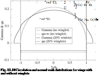
s is the curvilinear abscissa. For the main wing, aopt represents the effective incidence, i. e. aopt = a + ai, where a is the geometric incidence and ai the induced incidence. On the winglets, which are equipped with a symmetric profile, aopt = в = Ci, winglet /2п, represents the toe-in angle, since the induced normal wash is zero. In Fig. 11.10, a comparison of the optimum distributions of circulation and normal wash is presented for a simple wing and a wing with 20 % winglets, for a given lift coefficient CL = 2.0. The following comments can be made: the total lift is the same for both wings. The simple wing has an elliptic loading, with a high maximum root value, decreasing to zero at the tips, whereas the wing with winglets has a flatter distribution with lower root circulation and with higher loading at the winglet root. The downwash is constant for both wings, with a lower absolute value for the wing with winglets, which explains the lower induced drag given by

Winglet Design Подпись: (11.62)
Подпись: (11.61)

where S = (1 + at )b/2 represents the curvilinear length of the non planar wing and qn (s) is the normal wash such that qn (s) = w(s) along the main wing, qn (s) = v(s) on the left winglet and qn (s) = —v(s) on the right winglet. The winglets carry a load which does not contribute to lift, since lift is given by

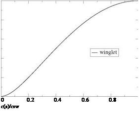
where y(s) represents the dihedral shape of the non planar wing, and dy/ds = 0 on the winglets. The winglets do not contribute to induced drag either since qn (s) = 0on the winglets. One should also note the flow singularity at the wing/winglet junction which shows as very large values of qn and requires a fine mesh system to capture the solution (200 points are used in this calculation). The induced drag of the wing with winglet, CDi = 0.0868, is compared to that of the simple wing, CDi = 0.106, which provides an 18 % decrease in induced drag and corresponds to an efficiency factor e = 1.22. The winglet geometry is shown in Fig. 11.11, where the chord distribution is normalized with the winglet root chord crw and the winglet height with atb/2. The winglet corresponds to the area located below the curve, the root being the bottom edge of the box and the trailing edge the right edge of the box.

1

Подпись:0.8

0.6

a

35

rl

0.4

0.2 0

Fig. 11.11 Winglet geometry

Static Stability

One of the most common design mistake made by student teams is a misplacement of the center of gravity. This results in the pilot having to constantly act on the tail deflection to maintain the airplane aloft or, in the worst case, ground rolling is immediately followed by a nose up and stall at take-off with likely loss of the airplane. The study of static stability clearly demonstrates a sufficient requirement for stability. For simplicity, we use a linear model obtained from the above model by assuming the following linear behavior of the coefficients

Cl (a) = a + Clo(tt), Cm, o (a) = a + Cm, o0 (tt) (11.46)

d a d a

Here the lift and moment slopes are assumed constant as well as the a = 0 lift and moment coefficients which depend only on the tail flap setting angle tt. We further assume small angles a and в and neglect the thrust in the first equation, Eq. (11.45). The system reduces to

Cl – Cw = 0

Cd – Ct + в Cw = 0 (11.47)

Cm, o + xfCw = 0

1ref

Substitution of Cw from the first equation into the third one yields an equation

for aeq

X

CM, o (aeq) + – CL (aeq) = CM, cg (aeq) = 0 (11.48)

Iref

representing the moment about the center of gravity. This is easily solved with the linear model as

Cm, o0(tt) + XcgfCL0(tt)

aeq to) =————- (1L49)

da + Iref da

The equilibrium incidence is controlled by the tail setting angle.

The equilibrium velocity is obtained from the definition of Cw and the first equa­tion, now that the lift Cl, eq = Cl (aeq) is known

Подпись: (11.50)Veq(tt) = J— Є

2 P Aref eL, eq

Finally, knowing the velocity and incidence, the coefficients of drag CD, eq and thrust CT, eq can be calculated and the slope of the trajectory evaluated as

в„ (tt) = CT’eq~ CD‘q (11.51)

eL, eq

Note that if Ct, eq < Cd eq the slope is negative and the trajectory is down. This is the case for a glider or when the engine is turned off since Ct = 0. This simple system also shows that for a glider, if one neglects the change in Reynolds number hence in CD0(Re), adding or subtracting mass at the center of gravity does not affect the equilibrium incidence aeq nor the slope angle вщ, and only affects the velocity on the trajectory which will change proportionally to VW".

Considering the moment of the aerodynamic forces at the center of gravity elim­inates the action of the weight. It is easy to show that, for static stability, one needs to satisfy the inequality

Static Stability Подпись: a

dCM^ (a) < 0 (11.52)

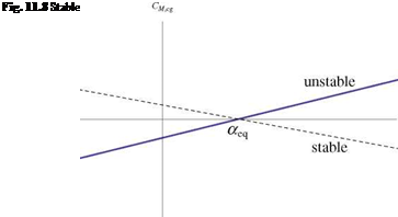
da

Indeed, if a perturbation, say a gust of wind, deviates the incidence from the equilibrium incidence by a Aa > 0 or nose up, a negative pitching or nose down moment ACM, cg < 0 is needed to restore the equilibrium incidence, and vice-versa, Fig. 11.8.

Подпись: xac Iref Static Stability Подпись: (11.53)

Another important point for the aerodynamic static stability of an airplane is the aerodynamic center (or neutral point) of the configuration. It is located between the aerodynamic center of the main wing and the aerodynamic center of the tail, proportionally to their areas and lift slopes as given by the linear model (neglecting the small fuselage contribution)

Note that its location is independent of tt. It is defined as the point about which the moment of the aerodynamic forces is independent of incidence, i. e. it satisfies

dC^O + Xa^dCb = 0 (11.54)

da lref da

Static Stability Подпись: (11.55)

Taking the derivative of the moment equation about the center of gravity, CM, cg (a) and satisfying the static stability inequality reads

Static Stability

Fig. 11.9 UC Davis entry at the 2006 aero design west competition


Static Stability

Static Stability

Подпись: lref Static Stability Подпись: (11.57)

Since the lift slope is positive, the condition reduces to

In other words, the center of gravity must be in front of the aerodynamic cen­ter. This is one of the most important design requirements, that was fulfilled as always in the model airplane of 2006, Fig. 11.9. The static margin defines the distance xa. c. – xc. g. as a percentage of the reference length as

Longitudinal Equilibrium

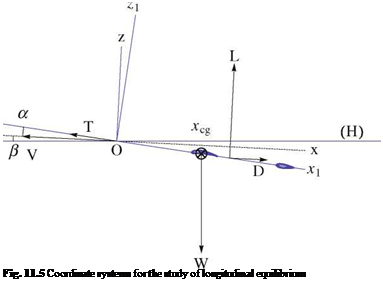
In this model, we consider the airplane flying at uniform velocity along a straight trajectory contained in a vertical plane. This corresponds to a steady situation, with no acceleration. The roll and yaw are both zero. Two coordinate systems are introduced: the aerodynamic coordinate system in which the x-axis is aligned with the airplane

Подпись: Fig. 11.5 Coordinate systems for the study of longitudinal equilibrium
velocity vector but oriented in the opposite direction and the z-axis upward; the other coordinate system is attached to the airplane, with the x1-axis along the fuselage axis and the z1-axis upward. The origin of the coordinate systems is placed at the nose of the airplane, see Fig. 11.5.

Подпись: CT Longitudinal Equilibrium Longitudinal Equilibrium Подпись: (11.44)

The incidence angle is the angle a = (Ox, Ox1), the slope angle is в = (H, Ox), both positive in the figure. The dimensionless coefficients, thrust, weight, lift, drag and moment coefficients are defined as

The lift force includes contributions from the main wing and the tail. The latter could be positive or negative, depending on the flight conditions. Note that the fuse­lage does not contribute to lift, according to slender body theory. The drag is evaluated with the best estimations of zero-lift drag, using flat plate formula for the wetted areas of streamlines elements, except for the main wing, and drag tables for the landing gear. The wing viscous drag is included in the wing viscous polar: The 2-D viscous polar has been obtained for a range of incidences corresponding to attached and separated flows with the well-known program XFOIL (or MSES for multi-element airfoils) of Dr. Mark Drela; the 3-D polar is derived from it, using Prandtl Lifting

Longitudinal Equilibrium

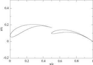
Fig. 11.6 Double element geometry

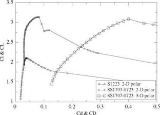
Line theory and the 2-D viscous polar at each span station. The 3-D polar is extended beyond stall. The induced drags of the main wing and the tail are included as well. The moment coefficient refers to the nose of the airplane. The geometry of the main wing double element profile is shown in Fig. 11.6, and the corresponding main wing 2-D and 3-D polars for the double element airfoil and wing (AMAT 2006) are shown in Fig.11.7 and compared with the 2-D polar of the Selig1223 airfoil at Reynolds number 200,000. It is interesting to note the high maximum lift coefficient of the Selig 1223 with Ci, max = 2.1 at this low Reynolds number and the even larger value achieved by the double element airfoil with Cl, max = 3.1. Note that the 2-D viscous

Longitudinal Equilibrium

Fig. 11.7 Viscous polars for the Selig 1223 airfoil and the double element airfoil and wing

drag of the double element is comparable to that of the S1223 drag near maximum lift up to Ci = 2.8. Another noteworthy point to make is the large induced drag of the AMAT wing which is a direct result of the medium wing aspect ratio AR = 8.75, indicating that at CL = 2.8, 88 % of the wing drag is induced drag.

The tail setting angle tt is the parameter that controls the equilibrium solution (trimmed equilibrium).

The longitudinal equilibrium equations consist of two equations for the forces and one for the moment. They read

CL + CT sin(a + t) — Cw cos в = 0 CD — CT cos(a + t) + Cw sin в = 0 (11.45)

Cm, o + TfCw cos(a + в) = 0

lref

Here, the propeller thrust makes an angle t with the airplane axis. There are three unknowns, the equilibrium incidence, aeq, velocity, Veq and slope, eeq. This is a highly nonlinear system, especially near the stall angle (maximum lift) since multiple values of a exist for a given CL. A combination of fixed-point iterations until close enough to the solution, followed by Newton’s iterations are needed to converge, when the solution exists, depending on the trim angle tt.

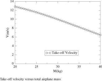
The equilibrium code is used concurrently with the acceleration result Vt.0.(M) to verify the feasibility of taking-off with a given total mass M. By “pulling on the stick”, or equivalently, by rotating the tail flap in the upward direction, the equilibrium incidence increases and the equilibrium velocity decreases. If it is possible to find a tail setting angle such that Veq < Vt.0. take-off can be achieved provided в > 3° and the incidence is not too close to the incidence of maximum lift. If all these conditions are fulfilled, it is possible to increase the mass of the airplane by adding payload weight thus increasing the possible score.

Acceleration Phase

Acceleration Phase Подпись: (11.37)

The acceleration phase is very critical as it determines the take-off velocity Vt. o. at the point where the pilot rotates the airplane to give it the incidence needed to begin climbing. The velocity V depends primarily on the power plant and the mass of the airplane. To a lesser extent it depends on the parasitic drags, aerodynamic and rolling friction drags. This is the reason why a high wing lift coefficient CLmax is needed in order to lift the highest possible weight. These can be modeled in more details with the acceleration code as

In this formulation, the thrust T [V] can be a more elaborate function of the velocity, say from wind tunnel measurements, although the previous linear model can be used when more detailed data is not available. The zero-lift drag Co0 will vary with velocity via the Reynolds number Re = p Vlref /jx based on the air density and dynamic viscosity, the velocity and the fuselage length lref. In general we will assume turbulent flow on most of the wetted area of the airplane. Therefore the viscous drag will be estimated as

Co0( Re) = Cf-f (11.38)

The reference drag coefficient, CDfref is estimated using the friction drag of each streamlined component and tables for blunt elements such as the landing gear of the airplane. The reference velocity is chosen typically as Vref = 20m/s. Accounting for the main wing, the tail, the fuselage and the landing gear, adding the different contributions with their corresponding reference areas, gives

Aref Cof ref = AmCom + AtCoft + AfCoff + Ag Cofg (11.39)

The induced drag is primarily due to the main wing because of the high lift coefficient, even during the rolling phase. The induced drag of the tail is neglected. The induced drag reads as previously

Подпись: CoiПодпись: (11.40)C2

CL

n eAR

The rolling friction is modeled with a coefficient of friction ak as

Acceleration Phase

ak depends on the materials in contact and for rubber on asphalt a value ak — 0.03 is used. The normal force acting on the tires is the apparent weight of the airplane, where

1 2

Wapp — M9 — 2 p V ArefCL (11.42)

This model is transformed into a system of 2 first-order ordinary differential equations in 2 unknowns x and V as

dx _ v

dt = v (її 43)

ddv — (T[V]- 2PV2Aref (Cdo[V] + CDi) – akWapp[V]) /M K ;

Integration is carried out with a 4th-order Runge-Kutta scheme and a time step At — 0.01 s. The total mass M is varied and a relation Vt. o.(M) is obtained for the take-off velocity achievable for different airplane masses. This result is important as it will determine the feasibility of taking-off and flying a round when running the equilibrium model. For an open class entry, the results are presented in Fig. 11.4.