Category AN INTRODUCTION TO FLAPPING WING AERODYNAMICS

Concluding Remarks

This chapter highlighted the rigid fixed-wing aerodynamics at the low Reynolds number range between 103 and 106. As the Reynolds number drops from 106 to 104 or lower, the lift-to-drag ratio of an airfoil substantially decreases. A thinner airfoil with modest camber is preferable for low Reynolds number flyers because it generates better lift-to-drag ratio and power efficiency compared to conventional airfoils.

At the Reynolds number around 104, the laminar-to-turbulent transition and LSB play important roles in determining airfoil performance. In this flow regime, the lift-to-drag polar exhibits zigzag characteristics that are due to the formation and burst of the LSB. Because of the effect of transition, the wing performance is expected to be sensitive to the free-stream turbulence intensity and wind gust. For low Reynolds number flight, drastically unconventional wing shapes may be bene­ficial. For example, a corrugated wing is less sensitive to the variation in Reynolds number, and it can provide a more favorable lift than a non-corrugated wing because the viscous effect substantially modifies the effective airfoil shape. In essence, pro­truding corrugation corners act as boundary-layer trips to promote the transition of the boundary layer from laminar to turbulent while remaining “attached” to the envelope profile of the high-speed streamlines; however, a corrugated wing can also experience higher drag coefficients compared with those of the smooth-surfaced airfoil.

A downwash movement induced by a TiV reduces the effective AoA of a wing. For a low AR and low Reynolds number wing, the induced drag by the TiV substan­tially affects its aerodynamic performance. The TiVs affect not only lift and drag generation but also potentially flight stability. Moreover, wind gust is a prominent factor in low Reynolds number flyers. The low Reynolds number aerodynamics often exhibits hysteresis in a gusty environment. The transition position varies with the local Reynolds number, and depending on the flow parameters, either drag or thrust can be generated from the unsteady aerodynamics.

As we have explored in the previous chapters, flying animals flap wings to create lift and thrust, as well as to perform remarkable maneuvers with rapid accelerations and decelerations. Insects, bats, and birds provide illuminating examples of using unsteady aerodynamics that can guide the design of MAVs.

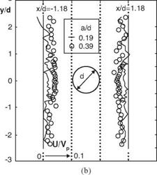
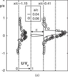
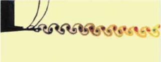
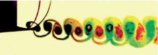
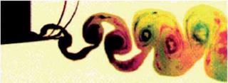
The first experimental work confirming the possibility of thrust generation on the unsteadily moving wing was conducted by Katzmayr in 1922 [168]. He investigated a fixed wing placed into an oscillating flow field. His studies validated the Knoller-Betz hypothesis [169] [170]. Both Knoller and Betz observed that the vertical motion of a flapping wing creates an effective AoA, generating an aerodynamic force with both lift and thrust components. Polonskiy [171] and Bratt [172] performed detailed visualizations of the large-scale vortex structures shed from harmonically plunging foils in a uniform flow and observed the characteristics of the vortex structures behind the airfoils. These experimental observations confirmed the Karman-Burgers thrust – generation hypothesis (i. e., the formation of a reverse Karman vortex street). In their experiments Polonskiy [171] and Jones et al. [173] showed the existence of different types of large-eddy structures generated by oscillating wings, as well as the vortex structures that are shed at an angle to the free-stream. Other researchers [174]- [178] studied the 2D flow structure behind oscillating foils and thrust generation, confirming that, depending on the parametric conditions, the wake structure can change from simple sinusoidal perturbations to two or four large-scale eddies. These typical flow structures were experimentally captured in flow visualization by Lai and Platzer [179]. Figure 3.1 shows the typical Karman vortex street behind a stationary NACA 0012, in which clockwise rotating vortices are shed from the upper surface and counterclockwise rotating vortices are shed from the lower surface; Figure 3.2a shows two pairs of vortices shed from the trailing edge of a NACA 0012 per plunge cycle, whereas Figures 3.2b and c show a single pair with a reverse Karman vortex street pattern. When an airfoil plunges at zero angle of incidence without an incoming flow, as shown in Figure 3.3a, a jet is produced by the flapping airfoil, and the streamwise velocity downstream of the airfoil is greater than the peak plunge velocity [180]. The jet appears to be biased toward the half-plane above the airfoil. This phenomenon was also observed by Jones et al. [181]. It occurs because, as soon as St exceeds approximately 0.8, the vortices shed from the trailing edge come too close together and start to interact with each other. In another experiment with a circular cylinder,

Figure 3.1. Vortical structure behind a stationary NACA 0012 airfoil for a free-stream velocity of 0.2 m/s [179].

the jet flow is not observed (see Fig. 3.3b). Therefore, it seems that the jet flow is caused by the detailed geometry such as curvature and asymmetry of the solid object. In another study, Taneda investigated the influence of traveling-wave characteristics associated with a flexible plate [182]. He revealed that the turbulence in the boundary layer is suppressed when the speed of propagation of the traveling wave exceeds that of the uniform incoming flow.

(a) ha = 0.0125 (St = 0.098)

(b) ha = 0.025 (St = 0.196)

(c) ha = 0.05 (St = 0.392)

Figure 3.2. Vortex patterns for a NACA 0012 airfoil oscillated in plunge for a free-stream velocity of approximately 0.2 m/s, a frequency of f = 2.5 Hz, Re = 2.1 x 10⁴, and various amplitudes of oscillation [179].

Figure 3.3. Non-dimensional mean streamwise velocity profiles generated by a (a) plunging airfoil, and (b) plunging cylinder at f = 5 Hz [180].

The interaction of large-scale eddies with oscillating wings has been noticed for many years in the context of observing fish bodies that generate large-scale eddies [183]. Gopalkrishnan et al. [184] and Streitlien and Triantafyllou [185] identified three types of interactions of the harmonically oscillating wing with vortices in the wake: (i) optimal interaction of the new vortices with the vortices shed by the wing, resulting in the generation of more powerful vortices in the reverse Karman vor­tex street; (ii) destructive interaction of new vortices with those shed by the wing, resulting in the generation of weaker vortices in the reverse Karman street; and (iii) interaction of vortex pairs with opposite sign shed from the wing, leading to the generation of a wide wake composed of vortex pairs that are shed at an angle to the free-stream. Furthermore, Triantafyllou et al. [186] observed that the inter­action between large-scale vortex structures generated by the fish body and vortex structures of the fin are important factors in determining the performance of swim­ming. In the “normal” case, the initial pair of large-scale vortices is generated by the body. Then the body-generated vorticity is redirected by the fin and interacts with the fin-generated vorticity to produce the vortex pair, which is “accurately controlled” by the fish. The timing of vortex formation, propagation, and its instan­taneous position are critical for efficient maneuvering and acceleration. Thus the control of vortex generation plays an important role in achieving high locomotion efficiency. In summary, depending on the features of the interactions between airfoil movement and the associated flow structure, either thrust or drag generation can be observed.

Another experiment discovered the delay of the leading-edge flow separation in unsteady motion. Devin et al. [187] indicated that, for a rigid wing with an AR of from 1 to 4 and a NACA 0012 section, no separation is observed up to the instantaneous AoA of 45°; in contrast, separation normally occurs at AoA = 15° (Re = 105) in the steady case. Moreover, investigations [188]-[190] have found that the stall does not come instantly when a wing is rapidly pitched beyond the static stall angle. Figure 3.4
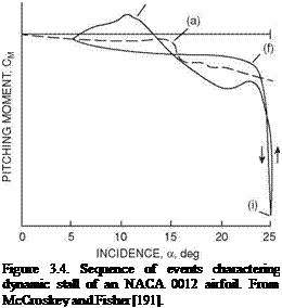
depicts the evolution of the flow structures in dynamic stall for a rapidly pitching NACA 0012 airfoil [191]. The reverse flow affects the pressure distribution (point b in Fig. 3.4) after the wing rapidly exceeds the static stall angle (point a in Fig. 3.4). This reversal progresses up on the airfoil upper surface and forms a vortex. This vortex initially appears near the leading edge of the airfoil (point c in Fig. 3.4),

enlarges, and then moves down the airfoil. The pitching moment reaches its negative peak, and then both lift and pitching momentum start to drop dramatically (points d and f in Fig. 3.4), producing the phenomenon known as dynamic stall. As the AoA decreases, the vortex moves into the wake and a fully separated flow develops on the airfoil. At the time instant when the AoA reaches its minimum AoA, lift has not reached its minimum value, which indicates that the dynamic stall process forms a hysteresis loop. Figure 3.4 shows such characteristics for the development of lift and pitching momentum. The amplitude and the shape of the hysteresis loop depend on the oscillation amplitude, mean AoA, and reduced frequency.

Jones and Platzer [192] developed and experimentally tested a flapping wing MAV. In their MAV configuration, lift is generated by a fixed forewing while thrust is produced by two flapping hindwings (see Fig. 1.15c) based on the thrust generation mechanisms discussed earlier. It is interesting to note that they also showed different possibilities of flapping airfoil usage, such as the reduction or suppression of flow separation behind blunt or cusped airfoil trailing edges. Willis et al. [193] and Persson et al. [194] presented a computational framework to design and analyze flapping MAV flight.

Moreover, pioneering works on flapping wing aerodynamics of biological flyers and swimmers have been published by Lighthill [40] and Weis-Fogh [68]. Further efforts, both in experiments and simulations, are documented by Ellington [65], Katz and Plotkin [195], DeLaurier [196], Smith [197], Vest and Katz [198], Ellington et al. [199], Liu and Kawachi [200], Dickinson et al. [201], Jones and Platzer [202] [203], and Wang [204], to name a few. A review of the characteristics of both flapping wings and fixed-wings has been given by Shyy et al. [205]. Recently, the number of publications related to flapping wing aerodynamics has greatly increased, indicating rapidly growing interest in this research field. Summaries of the recent efforts can be found in the books related to the aerodynamics of biological flyers [28] [206] and MAVs [36] [ 207].Valuable sources of information include special issues of the AIAA Journal (Vol. 46, 2008) and Experiments in Fluids (Vol. 46, No. 5, 2009), as well as numerous articles in the Encyclopedia of Aerospace Engineering (2010).

Conclusions and observations commonly made in these studies are that aero­dynamic phenomena associated with biological flights prominently feature unsteady motions, characterized by large-scale vortex structures, 3D flapping kinematics, and flexible wing structures. Furthermore, knowledge gained from studying biological flight shows that the steady-state aerodynamic theory can be seriously challenged as an explanation for the lift needed to keep biological flyers aloft [26] [65] [199].

The quasi-steady theories are constructed based on the instantaneous velocity, wing geometry, and AoA while employing the steady-state aerodynamic model. By neglecting the flow history, the quasi-steady approach greatly simplifies the time – dependent problem by converting it to a sequence of independent, steady-state problems, and so it has been frequently used in interpreting biological flight charac­teristics [4] [43] [60] [68] [80] [208]-[210]. For example, this approach has been used to estimate the mechanical power requirements of hummingbirds [211] and bum­blebees [212]. However, based on the theoretical analyses [213] and experimental measurements of tethered insects [214] [215], it has been found that the quasi­steady model is insufficient to predict the lift needed to support the weight of the insect body. In contrast, two studies [216] [ 217] involving a dynamically scaled, rigid­winged, flapping robotic flyer flapping in mineral oil suggest that the quasi-steady 2D blade element models can yield satisfactory agreement with the experimental measurement of aerodynamic forces. Further discussions and assessments regarding the quasi-steady aerodynamic model are presented in Section 3.6.

In this chapter we present various issues related to the aerodynamics of flap­ping flight of rigid wings. First, we discuss the scaling of flapping wing flight in terms of reduced frequency, Reynolds number, and Strouhal number. These non­dimensional parameters are important for investigating fluid physics of both rigid and flexible wings; discussion of flexible wing structures and aeroelasticity is presented in Chapter 4. Then, we discuss the main unsteady lift-enhancing aerodynamic mech­anisms associated with flapping wings, including delayed stall of leading-edge vortex (LEV); rapid pitch-up; wake capturing; interactions between LEV, trailing-edge vortex (TEV), and tip vortex (TiV); and clap-and-fling mechanisms. Subsequently, we look at the fluid physics in two different Reynolds number regimes in more detail. For both Reynolds number regimes, we investigate the effects of wing kinematics on the resulting flow field and aerodynamics.

For the Reynolds number regime of O(102), we compare the aerodynamics of the 3D hovering wing to its 2D counterpart and discuss the effects of free-stream fluctuations on aerodynamic performance. In this Reynolds number regime, intrigu­ing fluid dynamics phenomena are observed for a free-to-move vertically plunging rigid wing [218]. The vertical motion of the wing is imposed with sinusoidal kinemat­ics, whereas the wing is free to move in its horizontal directions. When the plunging frequencies are below a threshold value (i. e., Re (= p fhac/p) < 3.9 x 10²), the wing remains stationary in the horizontal plane, and the wakes shed in the flow form a symmetric structure. For the frequencies above this threshold value, such that Re > 3.9 x 10², the symmetry of the wake breaks, resulting in an inverted von Karman vortex street that is indicative of propulsion: the flapper moves forward. When the rigid wing is replaced with a flexible plate with the same geometry but with lower elastic modulus, the resulting forward speed is significantly greater than that of the rigid wing [219]. For more details we refer the reader to the literature (e. g., [218] [220] [221] for rigid wings and [219] [222] [223] for passively pitching wings).

For the Reynolds number regime of O(104) we focus on the effects of airfoil shapes on pitching and plunging wings in forward flight. Furthermore, we review approximate analysis for non-stationary airfoil aerodynamics and discuss several quasi-steady models. Finally, we highlight fluid physics associated with biological flapping flyer-like models, including the flyer’s scale effects on resulting flow struc­tures such as LEVs and spanwise flow.

Unsteady Tip Vortices

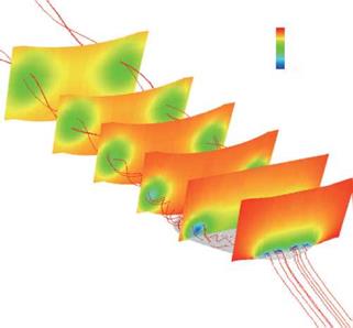
A low AR wing is susceptible to rolling instabilities (wobbling). This problem is particularly important in view of the strong gust effect on MAVs. Tang and Zhu [167] investigated the aerodynamic characteristic of a low AR wing. The wing has an elliptic planform, using the E-174 airfoil with an AR of 1.33. Based on the maximum chord length, the Reynolds number is 1 x 10⁴. Through numerical simulation and flow visualization in a water tunnel, they found that TiVs are unsteady in sizes and strengths when the AoA is larger than 11°. Figure 2.47a-c, on the right side of the figure, shows the positions of the TiVs at an AoA of 25° in the vertical plane (Trefftz plane) at three time instants. As time evolves, the left and right TiVs change their sizes and strengths. The asymmetric flow causes unequal drag between the two sides of the wing, which produces a yawing moment; the asymmetric flow also causes uneven lift, resulting in a rolling instability.

From the numerical results, they suggested that this unstable phenomenon is caused by the interaction between the secondary vortical flows and the TiVs. The separated vortical flows are on the upper surface of the wing. The schematic diagram on the left of Figure 2.47 shows that, as the wing incidence progressively increases from 5°, substantial time dependency of the TiVs is observed. At the AoA = 5°, the position of the separated vortical flow is around the trailing edge. As the incidence

Figure 2.47. Left: Schematic of the dynamics of tip vortices (viewed above the wing, secondary vortices are above the upper surface of the wing). Right: tip vortices streamlines in vertical planes (Trefftz plane) at about 0.5c behind trailing edge at the AoA of 25°, at three non­dimensional times (based on the free-stream velocity and maximum chord length): (a) t = 42, (b) t = 54, and (c) t = 62 (viewed from aft). From Tang and Zhu [167].

increases, the separating flow moves toward the leading edge. When the incidence reaches 15° or higher, the separating flows above the wing interact with the TiVs, causing them to become substantially unsteady. To date, MAV flight tests have not reported such rolling instabilities as a major barrier. This is apparently because the airfoil shapes used for MAV flyers are much thinner and do not induce as many separating flows above the wing surface. Nevertheless, the issue of unsteady TiVs needs to be investigated in the MAV design and flight test process.

Wingtip Effect

The wing shape chosen in Section 2.3.2 strives to maximize the wing area, and hence the lift, for a given dimension. However, the TiVs associated with the present low

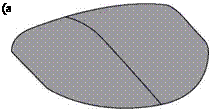
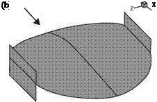
Figure 2.43. Wing-shape geometry: (a) modified wing; (b) endplates’ location on the modified wing [155].

AR wing also substantially affect its aerodynamics. It is well established that the TiV causes a downwash that modifies the pressure distribution on the wing surface and increases the induced drag. Various methods to reduce the induced drag by decreasing the TiV effects are described in the literature and confirmed by actual applications to aircraft wing design [164]. Viieru et al. [155] reported the implications of placing endplates at the wingtip, which is simple from the manufacturing point of view.

Viieru et al. [165] investigated the effects of endplates on MAV rigid-wing aerodynamics. In that study they simply added the endplate to the existing MAV wing to probe its effect on the TiV and overall aerodynamics, while retaining the wing shape. They observed that the endplate increases lift by reducing the downwash and increases the effective AoA. However, drag increases along with the curved endplate in part because the endplate behaves as a vertically placed airfoil and the additional form drag causes the overall lift-to-drag ratio to decrease.

To remedy the disadvantages of the endplates, Viieru et al. [155] studied three alternative wing geometries: the original wing discussed at the beginning of this chapter, a modified wing (Fig. 2.43a) with a trimmed tip, and a modified wing with endplates (Fig. 2.43b). Compared with the original wing, the trimmed wing has a shorter span of 14 cm and a small wing area of 155 cm2, whereas the root chord is the same length as with the original wing. The endplate attached to the modified wing, which is parallel to the flight direction, has a length of 4.4 cm and a height of 3.4 cm.

One can observe the vortex intensity and the circulation by looking at the slices perpendicular to the streamwise direction behind the wing. Behind the trailing edge, the flow can be approximated with a vortex core of constant rotation and a potential motion outside the core. The relation between the pressure at the vortex center and the circulation around a rigid rotating body is given by [166]:

Г2 = 4n M^center/A (2-23)

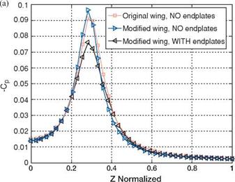
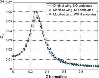
where r1 is the rigid body radius and Pcenter is the pressure at the rigid body cen­ter. Equation (2-23) shows that the vortex strength, measured by its circulation, is proportional with the pressure drop in the vortex core and its radius. In Figure 2.44, the pressure coefficient is plotted along the vortex core diameter at x/c = 3 behind the wing and x/c = 5. The amount of pressure drop inside the vortex core indicates

Figure 2.44. Pressure coefficient along the vortex core behind the wing at AoA = 6°: (a) x/c = 3; (b) x/c = 5 [155].

that the endplates reduce the vortex strength. Also, the modified wing without the endplates shows the strongest vortex.

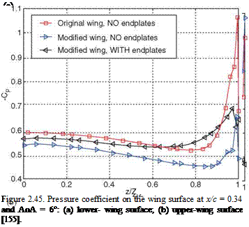
From the pressure contours and horizontal velocity contours, one observes that the endplate affects the flow field over the wing. The endplate slows down the flow near the wingtip. This decrease in velocity reduces the pressure drop on the upper-wing surface corresponding to the vortex core (Fig. 2.45a). In contrast, a lower velocity slightly below the wing increases the high-pressure area there, because more momentum is transferred to the wing as pressure instead of being shed as vorticity at the wingtip. The increase in the high-pressure zone on the lower wing surface in the presence of the endplate can be clearly seen from the spanwise pressure coefficient on the lower-wing surface plot (Fig. 2.45b).

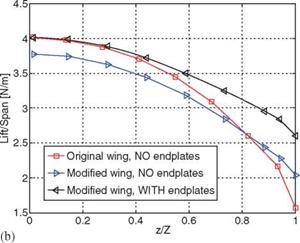
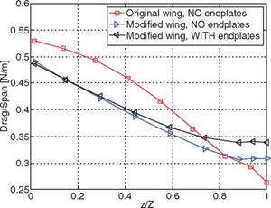
Figure 2.46 plots the spanwise lift distribution obtained by integrating the pres­sure difference along the local chord at a specified spanwise location. It clearly shows that when the endplates are attached the lift on each cross-section is higher compared to the wing without the endplate. With a smaller overall wing area, the modified wing with the endplates produces almost the same lift as the original wing. Furthermore, the modified wings (with and without an endplate) experience lower drag over almost 75 percent of the wingspan starting from the root.

In Table 2.1 the overall aerodynamic performance parameters are presented for the AoA = 6°. The modified wing configuration with endplates has a better lift-to-drag ratio than the baseline configuration (10 percent improvement). This

Figure 2.46. tribution at drag [155].

Подпись: (a)Подпись:improvement is mainly due to the reduction in drag caused by the modified wing shape because the total lift is essentially the same. In Table 2.2 the same parameters are presented for the AoA = 15°. The modified wing with endplates shows an increase of 1.4 percent in lift-to-drag ratio compared with the baseline configuration.
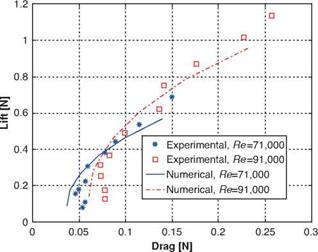
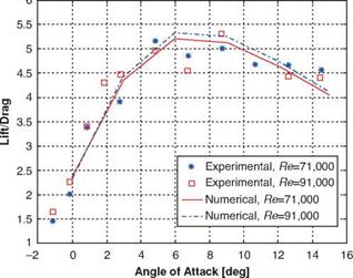
Table 2.1. Aerodynamic forces at a 6° AoA

AoA = 6°

Original MAV wing, no endplates

Modified MAV wing, no endplates

Modified MAV wing, with endplates

Lift (N)

0.49

0.44

0.49

Drag (N)

0.074

0.065

0.067

Lift/drag (-)

6.64

6.85

7.39

Source: [155].

Table 2.2. Aerodynamic forces at a 15° AoA

AoA = 15°

Original MAV wing, no endplates

Modified MAV wing, no endplates

Modified MAV wing, with endplates

Lift (N)

0.92

0.86

0.87

Drag (N)

0.22

0.21

0.21

Lift/drag (-)

4.16

4.15

4.22

Source: [155].

Aspect Ratio and Tip Vortices

Tip vortices (TiVs) exist on a finite wing because of the pressure difference between the upper and lower wing surface. The TiV establishes a circulatory motion over the wing surface and exerts great influence on the wing aerodynamics. Specifically, it increases the drag force. The total drag coefficient for a finite wing at subsonic speed can be written [44] as

C2

CD = CD, P + CD, F + —L, (2-22)

(b)

Figure 2.37. Numerical and experimental assessments of lift and drag over a MAV wing for different Reynolds numbers and AoAs [155]: (a) polar curve; (b) lift-to-drag ratio against the AoA.

where CD, P is the drag coefficient due to pressure; CD, F is the drag coefficient due to skin friction; e is the span efficiency factor, which is less than 1; AR is the aspect ratio; and C2L/(neAR) = CDi is the induced drag coefficient due to the existence of TiVs. Equation (2-22) demonstrates that the induced drag varies as the square of the lift coefficient; at a high AoA, the induced drag can be a substantial portion of the total drag. Furthermore, it illustrates that, as AR is decreased, the induced drag increases. The MAV wing presented by Ifju et al. [17] has a low AR of 1.4; therefore, it is important to investigate TiV effects on the wing aerodynamics. In general, TiV effects are twofold: (i) TiV causes downwash that decreases the effective AoA and increases the drag force [44], and (ii) it forms a low-pressure region on the top surface of the wing, which provides additional lift force [159].

(b)

Figure 2.38. Comparisons of CP on a rigid wing at the root for steady and unsteady computa­tions. (a) AoA = 6°; (b) AoA = 15°. From Lian and Shyy [158].

Figure 2.39 shows TiVs around the wing surface together with the streamlines at an AoA of 39° [160]. The vortical flow is usually associated with a low-pressure zone as shown in Figure 2.40. The pressure drop further strengthens the swirl by attracting more fluid toward the vortex core; meanwhile, the pressure decreases correspond­ingly in the vortex core. The low-pressure region created by the vortex generates additional lift. Toward the downstream, the pressure recovers to its ambient value, the swirling weakens, the diameter of the vortex core increases, and the vortex core loses its coherent structure.

Figure 2.39. Streamlines and vortices for a rigid wing at the AoA = 39°. The vortical structures are shown on selected planes. From Lian et al. [163].
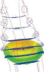
Figure 2.41 visualizes the evolution of the vortical structure with increasing AoA; it also presents the pressure distribution on the upper surface. At the AoA = 6°, TiVs are clearly visible even though they cover a small area and are of modest strength. The flow is attached to the upper surface and follows the chord direction. A low-pressure region is observed near the tip, caused by the vortical structure there.
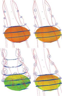
Even though the flow on the upper surface near the root tends to separate, the flow remains attached in the outer portion of the wing; hence the lift still increases with the AoA until, of course, massive separation occurs on most of the upper surface. For low AR wings, TiVs make considerable contributions to the lift. This

10060 9810

Figure 2.40. Pressure distribution around the rigid wing in the cross-sections with streamlines at the AoA = 39°. From Lian et al. [163].

Figure 2.41. Evolution of flow pattern for rigid wing vs. AoAs. From left to right, top to bottom, 6°, 15°, 27°, and 51°. From Lian and Shyy [154]

case is similar to that for delta wings. In his numerical study, Lian [161] observed that the low AR wing suffers less from separation. The wing is not subjected to sudden stall, but the lift coefficient levels off at very high AoAs. Torres and Mueller [162], in their experiments on low AR wings, found similar results. It should be noted that the analysis by Lian [161] included neither the fuselage nor the propeller.
This pressure drop can be seen from Figure 2.42a, which plots the spanwise pressure coefficient on the upper-wing surface at x/c = 0.4. At the AoA = 6° the spanwise pressure is almost uniform on the upper-wing surface, and the TiV causes the pressure drop to occur at approximately 90 percent of the half-span from the root. Figure 2.42 is illustrative in regard to pressure distributions versus the vortical structures. Note that the illustrated pressure distributions are not indicative of the total level of the pressure force.

Vortices strengthen with the increase in the AoA. At the AoA = 27°, as shown in Figure 2.41, tip vortices develop a strong swirl motion while entraining the sur­rounding flow. The low-pressure area increases as the AoA becomes higher. In Figure 2.42a, the pressure drop moves along the spanwise direction toward the root and now occurs at 75 percent from the root.

At lower AoAs, the vortex core position shows a linear relation with the inci­dence. This relation disappears at higher AoAs when the flow is separated on the upper surface. For example, at the AoA = 45°, the flow is separated at the leading edge, and the low-pressure zone covers more than 40 percent of the wing surface, which helps maintain the increase in lift force. At the AoA = 51°, a considerable

Figure 2.42. Spanwise pressure coefficient distributions at x/c = 0.4 for rigid wing at different AoAs. (a) Pressure coefficient at upper surface; (b) pressure coefficient at lower surface. From Lian and Shyy [154].

spanwise velocity component is seen, and the flow is separated from most of the upper surface (see Fig. 2.41). The separation on the upper-wing surface decreases the lift, and stall occurs.

As observed earlier, the TiVs have an important effect on the aerodynamics of low AR wings. Again, one major effect is the increase in induced drag for low AR wings. Equation (2-22) shows that the smaller the AR, the larger the induced drag.

Unsteady Phenomena at High AoAs

Vortex shedding causes more than just unsteadiness in aerodynamic performance. Cummings et al. [157] reported that, at large AoAs, the unsteady computations pre­dict noticeably lower lift coefficients than do the steady computations. The Reynolds

number in their study is higher than that of the MAV regime. Lian and Shyy [158] performed Navier-Stokes flow computations around a low AR wing under MAV flight conditions and found that the differences between the steady-state and the time-averaged lift are small, even at large AoAs in which unsteady phenomena such as vortex shedding are prominent. Nevertheless, the instantaneous flow structure varies substantially. Hence it can be misleading to simply examine the time-averaged flow field to estimate the MAV aerodynamic characteristics.

Figure 2.38 compares the pressure coefficients of a MAV wing designed by Ifju and co-workers[17], which are based on time-averaged unsteady computations and steady-state computations. In this design, the camber gradually decreases from the root toward the tip of the wing. Hence, the flow tends to separate first in the root region. At the AoA = 6° the time-averaged pressure coefficient closely matches the steady-state result. The time-averaged value yields a smooth pressure distribution; the steady-state result indicates a small recirculation zone. As the AoA becomes higher, there is little difference in the leading-edge region; on the contrary, clear differences exist in the separated regions.

Three-Dimensional Wing Aerodynamics

Low Reynolds number flyers use low AR wings, typically no larger than 5. For the MAVs developed by Ifju et al. [17] the AR is close to 1. Consequently, it is important to investigate the 3D flow structures around a low AR wing at low Reynolds numbers.

Lian and Shyy [154] and Viieru et al. [155] reported flow structures around a low AR rigid wing. The geometry follows the design of Ifju et al. [17] as discussed earlier. The wing has a span of 15 cm, a camber of 6 percent, a root chord of 13.3 cm, and a wing area of 160 cm2.

To confirm the capabilities of the Navier-Stokes solver, the computational results are first compared with wind-tunnel data measured for a MAV rigid wing with a

12.5 cm span, which has a smaller planform area than those used by Lian and Shyy [154] and Viieru et al. [155]. However, the overall shape and AR are similar. The experiment is conducted in a horizontal, open-circuit low-speed wind tunnel. It has a square entrance of a bell-mouth-inlet type, and it has several screens that provide low turbulence levels, less than 0.1 percent, in the test section. The test section is

91.4 cm x 91.4 cm and has a length of 2 m. The model under test is attached to a six – component strain-gauge sting balance used to measure the aerodynamic forces and moments. The AoA is controlled by computer and can be set in any sequence, steady or variable, in time. The force balance is calibrated from 1 gram to 500 grams, from precisely defined loading points. For more detailed information on the experimental measurements and uncertainty, we refer to Albertani et al. [156].

3

Phase ф

5

6

Подпись: 0 Figure 2.35. Phase and shape factors during one gust cycle on an SD7003 airfoil at the nonsteady Reynolds number, Rens = 1.98 x 10⁴: (a) phase; (b) shape factor [117].

The 12.5 cm wing configuration is tested at two different Reynolds numbers (7.1 x 10⁴ and 9.1 x 10⁴) based on the root chord length. The experimental data are obtained by averaging the values from multiple tests for each AoA and Reynolds number. In Figure 2.37a the lift versus drag curves are plotted for the two Reynolds numbers just mentioned. The figure demonstrates agreement between the compu­tational and experimental data. As shown in Figure 2.37b, within the considered Reynolds number range, the lift-to-drag ratio does not vary much. Furthermore, both experimental and computation data show that the best lift-to-drag ratio is reached for an AoA between 4° and 9°.

Effect of Unsteady Free-Stream

The real operating conditions for MAVs are quite different from the conventionally low-turbulence wind – and water-tunnel setup. In real flight, MAVs often operate in gusty environments. Obremski and Fejer [152] studied the effect of unsteady flow on transition. They experimented with a flat plate subject to a free-stream velocity varying sinusoidally with a mean:

U = Uref[1 + Na sin(2n ft)], (2-21)

in space and time by a disturbance wave packet. By applying a quasi-steady stability model, they concluded that in the high Rens range the wave packet is amplified rapidly and bursts into turbulence, whereas in the low range the wave packet bursts into turbulence at a much higher Reynolds number. Guided by their study, Lian and Shyy [117] investigated the influence of free-stream oscillations on the transition for separated flows. In their first test, they set Na = 0.33 and ы = 0.3, resulting in a Strouhal number of 0.0318 and a Rens of

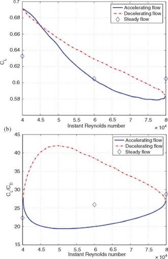
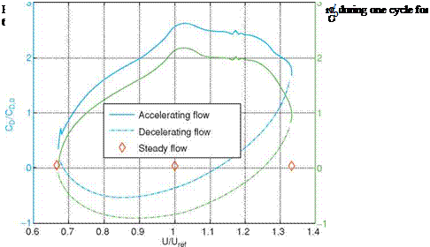
Figure 2.33. Aerodynamic coefficient of an SD7003 airfoil in a gusty environment during one cycle for non-steady Reynolds number, Rens = 9.9 x 10⁴, showing the hysteresis phenomenon: (a) lift coefficient; (b) lift-to-drag ratio [117].

9.9 x 10⁴. They kept the frequency ы well below the range of the expected unstable TS wave frequency, which is around 10 Hz.

Figure 2.33 shows the lift coefficient and lift-to-drag ratio during one selected cycle. Clearly, under a gust situation, the aerodynamic parameters display the hys­teresis. For example, when flow accelerates (the Reynolds number increases from 6 x 10⁴ to 8 x 10⁴), the lift coefficient does not immediately reach its correspond­ing steady-state value. Instead, the steady-state value is reached in the decelerating stage. Compared with a steady incoming flow, the gust leads to a higher lift coef­ficient at the low-velocity end and a lower lift coefficient at the high-velocity end. The lift-to-drag ratio variation during one cycle is substantial. For example, at the Reynolds number of 6 x 10⁴, the lift-to-drag ratio with a steady-state free-stream is

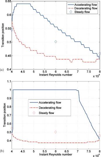
Figure 2.34. Transition position on an SD7003 airfoil during one cycle of the gust at (a) the non-steady Reynolds number, Rens = 9.9 x 10⁴; (b) the non-steady Reynolds number, Rens = 1.98 x 10⁴ [117].

around 26; for gust flow, the instantaneous lift-to-drag ratio reduces to 20 when the flow accelerates, but elevates to 38 when the flow decelerates.

Along with the variations in lift and drag, the transition position is also affected by the gust. As shown in Figure 2.34 the transition position moves toward the leading edge when the flow is accelerating, and it moves toward the trailing edge when flow is decelerating. During the accelerating stage, the instantaneous Reynolds number is increasing. As the Reynolds number increases, the flow experiences an early transition. In the simulation of Lian and Shyy [117], the transition point is simply linked to the computational grid point without further smoothing, resulting in a stair-stepped plot in Figure 2.34.

Lian and Shyy [117] also investigated a higher frequency of f = 0.24, five times higher than the previous case, resulting in a Rens of 1.98 x 10⁴, which is lower than the

critical value. Their numerical result shows that the transition position varies with the instantaneous Reynolds number (see Fig. 2.34). This result seemingly contradicts the observation of Obremski and Morkovin [153]. However, it should be noted that Obremski and Morkovin [153] drew their conclusion based on experimentation over a flat plate at a high Reynolds number (106), in which the flow is the Blasius type and experiences natural transition. In the test of Lian and Shyy [117], in contrast, the separated flow amplifies the unstable TS wave at such a great rate that it results in a faster transition to turbulence, typical of the bypass-transition process.

Comparison of the transition position at two different non-steady Reynolds numbers reveals that the flow experiences transition for the entire oscillation cycle at a higher non-steady Reynolds number, whereas at the lower value the flow becomes laminar at the early accelerating state and remains laminar until the instant Reynolds number reaches around 7 x 10⁴. It is possible that during the decelerating stage the transition position moves toward the trailing edge because of the lowered Reynolds number. At a higher non-steady Reynolds number (i. e., at a lower frequency), the deceleration has less impact on the transition and the LSB can sustain itself; at a lower non-steady Reynolds number (i. e., at a higher frequency), the deceleration has more impact on the transition and the LSB cannot adjust itself with the high rate of change needed to maintain the closed bubble and the LSB bursts. A closed LSB forms only when the Reynolds number reaches 7 x 10⁴. To better appreciate this phenomenon, see the phase and shape factor during one cycle plotted in Figure 2.35.

Another interesting observation at Ren = 1.98 x 10⁴ is the drag coefficient shown in Figure 2.36. During the decelerating stage the gusty flow produces thrust. Analysis shows that the thrust is due to the friction force.

Effect of Free-Stream Turbulence

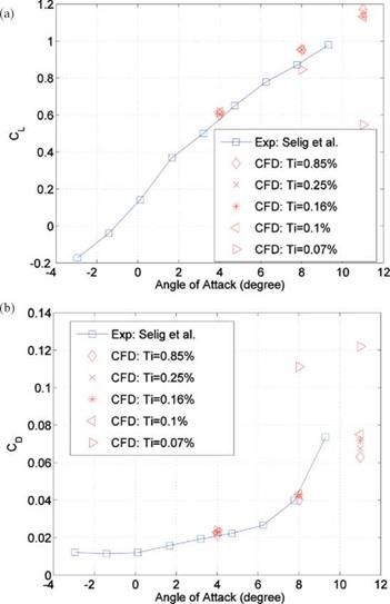
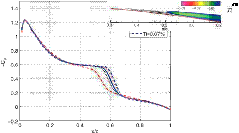
When both the AoA and chord Reynolds number are fixed, increasing the free – stream turbulence level prompts an earlier transition. The aerodynamic characteris­tics under different turbulence intensities were investigated by Lian and Shyy [117]. The lift and drag coefficients from their research are shown in Figure 2.27. At the AoA = 4°, there is no noticeable difference in the lift and drag coefficients among the five tested turbulence levels. This seemingly contradicts the pressure coefficient plot in Figure 2.28 because the integrated area between CP = 0 and CP distributio

At the AoA = 8°, there is a drastic decrease in the lift coefficient and an increase in the drag coefficient when Ti decreases to 0.07 percent. Analysis of the flow structure reveals that, at such a low-turbulence level, the flow fails to reattach after its initial separation. This separation bubble causes the lift coefficient to drop by 10 percent and the drag coefficient to increase by more than 150 percent. Similar conclusions can also be drawn for the case of AoA of 11°.

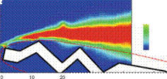
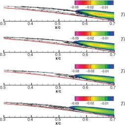
In general, with the increase in the free-stream turbulence level, the LSB becomes thinner and shorter. This is clearly shown in Figure 2.29. From the same figure it can also be seen that the shear stress decreases with the turbulence level. Because of the viscous effect, the boundary layer and the LSB change the effective shape of the airfoil. As shown in Figure 2.30, the free-stream with a higher turbulence level results in a relatively thinner effective airfoil than that with a lower turbulence level.

O’Meara and Mueller [150] experimentally studied the effects of free-stream turbulence on the separation bubble characteristics of a NACA 663-018 airfoil. They reported that, as the disturbance level is increased, the bubble is reduced in

Spanwise

vorticity

(1000*1/s)

:n:: 050


Подпись: oouo/л oouo/л oouo/л oouo/л oouo/л

Velocity

(m/s)


30 40 50 0 10 20 30

X/C*100 X/C*100

(c) Ensemble-averaged velocity fields


15


Velocity

(m/s)


T. K.E


10

о

5

О

0

-5


Щ 0.085 0.075 0.065 0.055 0.045 0.035 I 0.025 0.015 0.005


Figure 2.27. Lift and drag coefficients against the AoA at different turbulence levels for an SD7003 airfoil at the Reynolds number, Re = 6 x 10⁴: (a) lift coefficient; (b) drag coefficient

[117].

both length and thickness, which is consistent with the observations from Figures 2.29 and 2.30. As we discuss later, the effects of increasing the disturbance level resemble the effects of increasing the chord Reynolds number. O’Meara and Mueller [150] also reported that the suction peak grows in absolute magnitude with the disturbance level. However, as shown in Figure 2.28, the pressure peak over the SD7003 airfoil is not sensitive to the disturbance level. These two conclusions are drawn based on different test cases, in which the bubble size and Reynolds number are quite different. The results in Figure 2.31 are obtained at a chord Reynolds number of 1.4×10⁵; occupying around 7 percent of chord length, the bubble is short and, as previously discussed, only locally affects the pressure distribution. In contrast, in
the test of Lian and Shyy [117], the bubble covers more than 30 percent of the upper surface at the Reynolds number of 6 x 10⁴ and the AoA = 4°, and the bubble falls into the long-bubble category. This hypothesis is further confirmed by the fact that, at the Reynolds number of 6 x 10⁴ and the AoA = 8°, wherein the bubble is 8 percent of the chord, the pressure peak magnitude does increase with the increase in the disturbance level.

Подпись: 0.07%Подпись:Подпись: 0.16%Подпись: 0.25%

Figure 2.29. Streamlines and normal­ized shear-stress contours at the AoA = 4° for different turbulence levels for an SD7003 airfoil at the Reynolds number, Re = 6 x 10⁴ [117].

Подпись: Figure 2.30. Effective airfoil shapes at different turbulence levels for an SD7003 airfoil at the Reynolds number, Re = 6 x 10⁴ [117].

Mueller et al. [151] presented the effects of free-stream turbulence on lift and drag performances of a Lissaman 7769 airfoil. As shown in Figure 2.32, the hysteresis characteristics of the lift and the drag coefficients can be observed for the free – stream disturbance intensity of around 0.10 percent. The hysteresis loop, however, disappears as the free-stream turbulence intensity is increased to 0.30 percent. They suggested that the surface roughness can also produce the same result. Furthermore, the disappearance of the hysteresis loop for aerodynamic lift and drag coefficients at high free-stream turbulence intensity seems to be related to the change in flow structure.

Re = 104-106

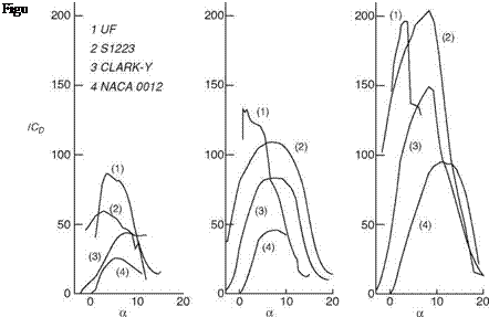
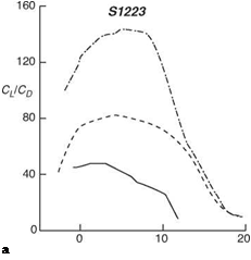
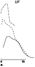
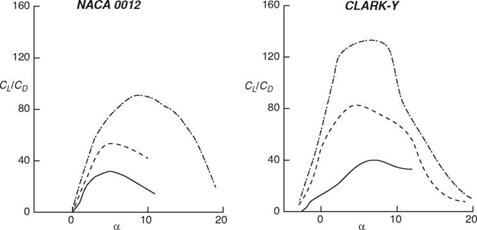
Shyy et al. [147] evaluated the aerodynamics between the chord Reynolds number of 7.5 x 10⁴ and 2 x 10⁶, using the XFOIL code [96], for two conventional airfoils – NACA 0012 and CLARK-Y – and two low Reynolds number airfoils: S1223 [148] and an airfoil modified from S1223, which is called UF (see Fig. 2.22). Figures 2.23 and 2.24 show the power index, cL/2/Cd, and lift-to-drag ratio, CL/CD, plots at three Reynolds numbers: 7.5 x 10⁴ , 3 x 10⁵, and 2 x 10⁶. It is noted that for steady-state flight, the power required for maintaining a fixed-wing vehicle in the air is

Подпись: P = W

Подпись: Area 0.08220 Thick. 0.12003 Camber 0.00000 RadLE 0.01527 40TE 15.97°

(2-20)

where P and W are the required power and vehicle weight, respectively. For all air­foils, the CL/CD ratio exhibits a clear Reynolds number dependency. For Reynolds numbers varying between 7.5 x 10⁴ and 1 x 10⁶, CL/CD changes by a factor of 1-3 for the airfoils tested. Except for the UF airfoil, which is very thin, the range of the AoA within which aerodynamics is satisfactory becomes narrower as the Reynolds num­ber decreases. Clearly, the camber is important. NACA 0012, with 0 percent camber, and CLARK-Y with 3.5 percent camber, yield a less satisfactory performance under all three Reynolds numbers. S1223 and UF, both with 8.89 percent camber, perform better.

Finally, NACA 0012, CLARK-Y, and S1223 all have maximum thickness of about 0.12c. The UF airfoil, in contrast, is considerably thinner, with a maximum thickness of 0.06c. It is interesting to compare the Reynolds number effect. At the Reynolds number Re = 2 x 10⁶, S1223 and UF airfoil have comparable peak per­formances in terms of cL/2/Cd and CL/CD; however, S1223 exhibits a wider range of acceptable AoAs. At the Reynolds number Re = 7.5 x 10⁴, the situation is quite different. UF, the thinner airfoil with identical camber, exhibits a substantially bet­ter aerodynamic performance while maintaining a comparable range of acceptable AoAs. This is consistent with the finding of Okamoto et al. [139] discussed previously.

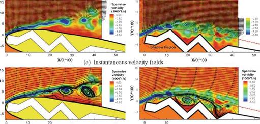
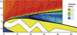
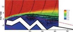
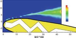
Murphy and Hu [149] experimentally measured the aerodynamic characteristics of a bio-inspired corrugated airfoil compared with a smooth-surfaced airfoil and a flat plate at the chord Reynolds numbers of 5.8 x 10⁴ and 1.25 x 10⁵. Their measurement result revealed that the corrugated airfoil has better performance in providing higher lift and preventing large-scale flow separation and airfoil stall at low Reynolds num­bers (<105) than the smooth-surfaced airfoil and the flat plate, as shown in Figures 2.25 and 2.26. However, the corrugated airfoil was found to have higher drag coef­ficients compared to those of the smooth-surfaced airfoil and the flat plate at low

Подпись: a Подпись: J L 0 10 a Подпись:

Подпись: 160 |-

120

CJCD

80
40
0

Figure 2.24. CL/CD against AoA plots for the four airfoils [147]. —, the Reynolds number,

Re = 7.5 x 10⁴; —, the Reynolds number, Re = 3 x 10⁵; ……. , the Reynolds number, Re =

2 x 10⁶.

AoAs (<8°). The corrugated airfoil is less sensitive to the variation in the Reynolds number. Furthermore, as shown in Figure 2.26 Murphy and Hu’s [149] flow measure­ment suggested that the protruding corrugation corners would act as boundary-layer trips to promote the transition of the boundary layer from laminar to turbulent while remaining “attached” to the envelope profile of the high-speed streamlines.

Re = 103-104

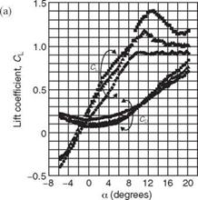
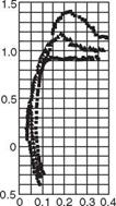
Okamoto et al. [139] experimentally studied the effects of wing camber on wing performance with Reynolds numbers as low as 103 to 104. Their experiment used rectangular wings with an AR of 6, constructed from aluminum foil or balsa wood. Figure 2.12 illustrates the effects of camber on the aerodynamic characteristics. As the camber increases, the lift coefficient slope and the maximum lift coefficient increase as well. The increase in camber pushes both the maximum lift coefficient and maximum lift-to-drag ratio to a higher AoA. More interestingly, the 3 percent camber airfoil shows a stall-resisting tendency, with the lift just leveling off above an AoA of 10°. Although it has the disadvantage of a high drag coefficient, the low-camber airfoil is less sensitive to the AoA and therefore does not require sophisticated steering.

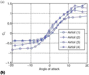
Sunada et al. [140] compared wing characteristics at the Reynolds number of 4 x 10³ using fabricated rectangular wings with an AR of 7.25; representative wings are shown in Figure 2.13. After testing 20 wings, they concluded that the wing

Figure 2.12. Effects of circular camber on the aerodynamic characteristics of a rect­angular model wing made from aluminum foil, thickness 0.3 mm and chord length 30 mm. Each symbol refers to a different camber, as shown in the panel on the right side of the figure. (a) CL and CD against the AoA; (b) polar curve. From Okamoto et al. [139].

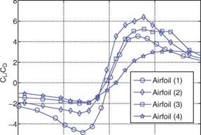
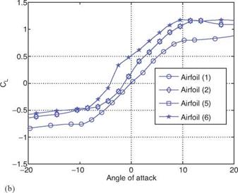
Подпись: 0.6Подпись: 0.4Подпись:Подпись: C?Подпись: -0.2Подпись:Подпись: Lift coefficient, CLПодпись:Подпись: 3%Подпись: >6%Подпись:Подпись: Drag coefficient, CDПодпись: X Ф > c о о тз ь_ со 5 а. => performance can be improved with a modest camber of around 5 percent. Figure 2.14 shows the lift and drag coefficients against the AoA. At the Reynolds number, Re = 4 x 10³, the effect of camber on aerodynamics found by Sunada and colleagues is similar to that reported by Okamoto et al. [139]. In both experiments, the lift – curve slope increases with the camber; a higher camber wing has a higher stall AoA and generally a larger drag coefficient than a lower camber wing at the same AoA. If we further compare wings of comparable cambers, we notice that they have almost the same stall angle. Sunada et al. [140] also investigated the impact of maximum-camber location, as shown in Figure 2.15. They found that both lift and drag coefficients increase as the position of the maximum camber approaches the trailing edge. In terms of lift-to-drag ratio, the maximum value is obtained when the maximum camber is positioned at 25 percent chord.

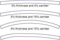
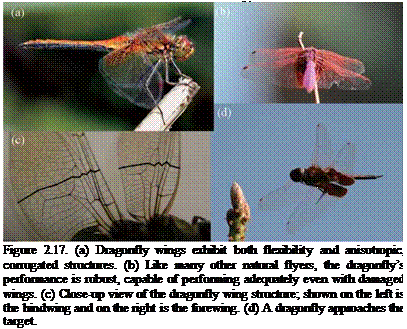
Okamoto et al. [139] also studied the effects of airfoil thickness. They found that the wing’s aerodynamic characteristics deteriorate as its thickness increases (see Fig. 2.16). In contrast to conventional airfoils, which are smooth and streamlined, insect airfoils exhibit rough surfaces; for example, the cross-sectional corrugations of dragonfly wings (shown in Fig. 217c) or scales on the wing surface (butterfly and moth). Evidence has shown that the corrugated wing configuration confers both structural and aerodynamic benefits to the dragonflies. First, it is of critical

Airfoil (1) Airfoil (2) Airfoil (3) Airfoil (4)

Airfoil (5) Airfoil (6)


Rectangular airfoil with 5% thickness

5% thickness and 5% camber at 25% chord


Figure 2.13. Airfoil shapes tested in Sunada et al. [140]. Redrawn from the original reference with permission.


5% thickness and 5% camber at 75% chord


Подпись: (b) Подпись: -10Подпись: 10Figure 2.14. The effect of maximum camber location on the aerodynamic characteristics at the Reynolds number, Re = 4 x 10³. Redrawn from Sunada et al. [140] with permission.
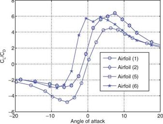
-6

-20


0

Angle of attack


20


Figure 2.15. The effect of maximum camber location on the aerodynamic characteristics at the Reynolds number, Re = 4 x 10³. Redrawn from Sunada et al. [140] with permission.

importance to the stability of the wing’s ultralight construction. Second, in visualizing experiments using corrugated wings, Newman and Low [141] and Buckholz [142] showed that this geometry helps improve aerodynamic performance. The reason, as suggested by Kesel, is that vortices fill the profile valleys formed by these bends and therefore smooth the profile geometry [143].

Kesel [144] compared the aerodynamic characteristics of dragonfly wing sections with conventionally designed airfoils and flat plates at the Reynolds numbers of 7.88 x 10³ and 104. She concluded that corrugated airfoils, such as those seen in dragonflies (see Fig. 2.17), have very low drag coefficients closely resembling those of flat plates, whereas the lift coefficient is much higher than those of flat plates. She also investigated the performance of the airfoil by simply filling the valleys with solid

Подпись: Є

Figure 2.16. Effects of thickness on the aerodynamic characteristics of a curved-section model wing (camber 9%). Each symbol refers to a different airfoil shape as shown in the panel on the right; c, chord length; t, thickness; Re, Reynolds number. All dimensions are given in millimeters. (a) CL and CD against the AoA; (b) polar curve. From Okamoto et al. [139].

Подпись: Profile 3A
Подпись: Figure 2.18. Geometry of wing profiles used in the study of Kesel [144]. Profiles 1, 2, and 3 are constructed using measurement taken from a dragonfly wing. Profiles 1A, 2A, and 3A are built by connecting the peaks of the respective cross-sections.

materials (as illustrated in Fig. 2.18). Figure 2.19 highlights the key features of the lift and drag values against AoAs between the three natural and filled airfoil profiles. Figure 2.20 shows the corresponding lift-drag polar. These plots, taken from Kesel [144], show that the filled airfoils have less favorable aerodynamic performances. Therefore it is clear that the performance of such corrugated airfoils is influenced by their “effective” shape, which is characterized by the viscous effects, as previously discussed. In particular, the viscosity and associated vortical structures result in an airfoil with cambered geometry [144].

Vargas et al. [145] numerically investigated the effects of the pleats on the aerodynamic performance at Re = 102-104 with the range of AoA from 0° to 10°. The pleats’ effect on the flow is most evident at low AoAs where the flow is basically attached to both surfaces of the wing section. At those AoAs, although the pleated airfoil experiences an increase in the pressure drag, this increase is more than offset by a concomitant decrease in the shear drag. The reduction in the shear drag occurs because there are recirculation zones inside the cavities formed by the pleats, which lead to a negative shear drag contribution (see Fig. 2.21). Also noted by Vargas et al. [145] is that, beyond the Reynolds number of 5.0 x 10³ and an AoA of 5°, the pleated airfoil performs better than the flat plate and the profiled airfoil. Kim et al. [146] also numerically investigated the aerodynamic performance of the dragonfly wing at Re = 1.5 x 102,1.4 x 103, and 105 with an AoA ranging from 0 to 40°. Their

due to the viscous effects of the flow around the wing, the original airfoil shape behaves effectively like a smooth envelope contour resembling a conventional air­plane airfoil. Of course, for dragonfly, this explanation is incomplete because the unsteady fluid physics associated with the flapping motion and deformable wing shapes and the interactions between fore – and hindwings interplay with significant effects.