Category Fundamentals of Aerodynamics

Kelvin’s Circulation Theorem and the Starting Vortex

In this section, we put the finishing touch to the overall philosophy of airfoil theory before developing the quantitative aspects of the theory itself in subsequent sections. This section also ties up a loose end introduced by the Kutta condition described in the previous section. Specifically, the Kutta condition states that the circulation around an airfoil is just the right value to ensure that the flow smoothly leaves the trailing edge. Question: How does nature generate this circulation? Does it come from nowhere, or is circulation somehow conserved over the whole flow field? Let us examine these matters more closely.

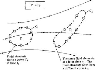
Consider an arbitrary inviscid, incompressible flow as sketched in Figure 4.15. Assume that all body forces f are zero. Choose an arbitrary curve C, and identify the fluid elements that are on this curve at a given instant in time t{. Also, by definition the circulation around curve Cj is Ті = — fc V • ds. Now let these specific fluid elements move downstream. At some later time, t2, these same fluid elements will form another curve C2, around which the circulation is Г2 = – fr У • ds. For the conditions stated above, we can readily show that Tt = Г2. In fact, since we are following a set of specific fluid elements, we can state that circulation around a closed curve formed by a set of contiguous fluid elements remains constant as the fluid elements move throughout the flow. Recall from Section 2.9 that the substantial derivative gives the time rate of change following a given fluid element. Hence, a mathematical statement of the above discussion is simply

[4.11]

which says that the time rate of change of circulation around a closed curve consisting of the same fluid elements is zero. Equation (4.11) along with its supporting discussion

image319

Figure 4.15 Kelvin’s theorem.

is called Kelvin’s circulation theorem.[15] Its derivation from first principles is left as Problem 4.3. Also, recall our definition and discussion of a vortex sheet in Section 4.4. An interesting consequence of Kelvin’s circulation theorem is proof that a stream surface which is a vortex sheet at some instant in time remains a vortex sheet for all times.

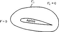
Kelvin’s theorem helps to explain the generation of circulation around an airfoil, as follows. Consider an airfoil in a fluid at rest, as shown in Figure 4.16a. Because V = 0 everywhere, the circulation around curve C is zero. Now start the flow in motion over the airfoil. Initially, the flow will tend to curl around the trailing edge, as explained in Section 4.5 and illustrated at the left of Figure 4.12. In so doing, the velocity at the trailing edge theoretically becomes infinite. In real life, the velocity tends toward a very large finite number. Consequently, during the very first moments after the flow is started, a thin region of very large velocity gradients (and therefore high vorticity) is formed at the trailing edge. This high-vorticity region is fixed to the same fluid elements, and consequently it is flushed downstream as the fluid elements begin to move downstream from the trailing edge. As it moves downstream, this thin sheet of intense vorticity is unstable, and it tends to roll up and form a picture similar to a point vortex. This vortex is called the starting vortex and is sketched in Figure 4.16b. After the flow around the airfoil has come to a steady state where the flow leaves the trailing edge smoothly (the Kutta condition), the high velocity gradients at the trailing edge disappear and vorticity is no longer produced at that point. However, the starting vortex has already been formed during the starting process, and it moves steadily downstream with the flow forever after. Figure 4.16b

image320

(a) Fluid at rest relative to the airfoil


Cj

image321

(b) Picture some moments after the start of the flow

Figure 4.1 6 The creation of the starting vortex and the

resulting generation of circulation around the airfoil.


shows the flow field sometime after steady flow has been achieved over the airfoil, with the starting vortex somewhere downstream. The fluid elements that initially made up curve C i in Figure 4.16a have moved downstream and now make up curve C2, which is the complete circuit abcda shown in Figure 4.16b. Thus, from Kelvin’s theorem, the circulation Г2 around curve C2 (which encloses both the airfoil and the starting vortex) is the same as that around curve C1, namely, zero. Г2 = F| = 0. Now let us subdivide C2 into two loops by making the cut bd, thus forming curves C3 (circuit bcdb) and C4 (circuit abda). Curve C3 encloses the starting vortex, and curve C4 encloses the airfoil. The circulation Г3 around curve C3 is due to the starting vortex; by inspecting Figure 4.16b, we see that Г3 is in the counterclockwise direction (i. e., a negative value). The circulation around curve C4 enclosing the airfoil is Г4. Since the cut bd is common to both C3 and C4, the sum of the circulations around C3 and C4 is simply equal to the circulation around C2:

r3 + Г4 = Г2

However, we have already established that Г2 = 0. Hence,

Г4 = – r3

that is, the circulation around the airfoil is equal and opposite to the circulation around the starting vortex.

This brings us to the summary as well as the crux of this section. As the flow over an airfoil is started, the large velocity gradients at the sharp trailing edge result in the

formation of a region of intense vorticity which rolls up downstream of the trailing edge, forming the starting vortex. This starting vortex has associated with it a coun­terclockwise circulation. Therefore, as an equal-and-opposite reaction, a clockwise circulation around the airfoil is generated. As the starting process continues, vorticity from the trailing edge is constantly fed into the starting vortex, making it stronger with a consequent larger counterclockwise circulation. In turn, the clockwise circu­lation around the airfoil becomes stronger, making the flow at the trailing edge more closely approach the Kutta condition, thus weakening the vorticity shed from the trailing edge. Finally, the starting vortex builds up to just the right strength such that the equal-and-opposite clockwise circulation around the airfoil leads to smooth flow from the trailing edge (the Kutta condition is exactly satisfied). When this happens, the vorticity shed from the trailing edge becomes zero, the starting vortex no longer grows in strength, and a steady circulation exists around the airfoil.

Isentropic Relations

We have defined an isentropic process as one which is both adiabatic and reversible. Consider Equation (7.14). For an adiabatic process, Sq = 0. Also, for a reversible process, 6/.virrev = 0. Thus, for an adiabatic, reversible process, Equation (7.14) yields ds = 0, or entropy is constant; hence, the word “isentropic.” For such an isentropic

Equation (7.32) is very important; it relates pressure, density, and temperature for an isentropic process. We use this equation frequently, so make certain to brand it on

your mind. Also, keep in mind the source of Equation (7.32); it stems from the first law and the definition of entropy. Therefore, Equation (7.32) is basically an energy relation for an isentropic process.

Why is Equation (7.32) so important? Why is it frequently used? Why are we so interested in an isentropic process when it seems so restrictive—requiring both adiabatic and reversible conditions? The answers rest on the fact that a large number of practical compressible flow problems can be assumed to be isentropic—contrary to what you might initially think. For example, consider the flow over an airfoil or through a rocket engine. In the regions adjacent to the airfoil surface and the rocket nozzle walls, a boundary layer is formed wherein the dissipative mechanisms of viscosity, thermal conduction, and diffusion are strong. Hence, the entropy increases within these boundary layers. However, consider the fluid elements moving outside the boundary layer. Here, the dissipative effects of viscosity, etc., are very small and can be neglected. Moreover, no heat is being transferred to or from the fluid element (i. e., we are not heating the fluid element with a Bunsen burner or cooling it in a refrigerator); thus, the flow outside the boundary layer is adiabatic. Consequently, the fluid elements outside the boundary layer are experiencing an adiabatic reversible process—namely, isentropic flow. In the vast majority of practical applications, the viscous boundary layer adjacent to the surface is thin compared with the entire flow field, and hence large regions of the flow can be assumed isentropic. This is why a study of isentropic flow is directly applicable to many types of practical compressible flow problems. In turn, Equation (7.32) is a powerful relation for such flows, valid for a calorically perfect gas.

This ends our brief review of thermodynamics. Its purpose has been to give a quick summary of ideas and equations which will be employed throughout our subsequent discussions of compressible flow. For a more thorough discussion of the power and beauty of thermodynamics, see any good thermodynamics text, such as References 22 to 24.

Consider a Boeing 747 flying at a standard altitude of 36,000 ft. The pressure at a point on the | Example 7.1

wing is 400 lb/ft2. Assuming isentropic flow over the wing, calculate the temperature at this

point.

Solution

Подпись: or
image495,image496

At a standard altitude of 36,000 ft, px = 476 lb/ft2 and Тх = 391 °R. From Equation (7.32),

Surface Integrals

Consider an open surface S bounded by the closed curve C, as shown in Figure 2.9. At point P on the surface, let dS be an elemental area of the surface and n be a unit vector normal to the surface. The orientation of n is in the direction according to the right-hand rule for movement along C. (Curl the fingers of your right hand in the direction of movement around C; your thumb will then point in the general direction of n.) Define a vector elemental area as dS = ndS. In terms of dS, the surface integral over the surface S can be defined in three ways:

її p dS = surface integral of a scalar p over the 5 open surface S (the result is a vector)

If A • dS = surface integral of a vector A over the 5 open surface S (the result is a scalar)

N A x dS = surface integral of a vector A over the 5 open surface S (the result is a vector)

Surface Integrals image97 Подпись: s

If the surface S is closed (e. g., the surface of a sphere or a cube), n points out of the surface, away from the enclosed volume, as shown in Figure 2.10. The surface integrals over the closed surface are

Governing Equation for Irrotational, Incompressible Flow: Laplace’s Equation

We have seen in Section 3.6 that the principle of mass conservation for an incom­pressible flow can take the form of Equation (3.39):

V • V = 0 [3.39]

In addition, for an irrotational flow we have seen in Section 2.15 that a velocity potential ф can be defined such that [from Equation (2.154)]

[2.154]

Therefore, for a flow that is both incompressible and irrotational, Equations (3.39) and (2.154) can be combined to yield

Подпись: or Подпись: V20 = 0 Подпись: [3.40]

V • (V</>) = 0

Equation (3.40) is Laplace’s equation—one of the most famous and extensively stud­ied equations in mathematical physics. Solutions of Laplace’s equation are called harmonic functions, for which there is a huge bulk of existing literature. Therefore, it is most fortuitous that incompressible, irrotational flow is described by Laplace’s equation, for which numerous solutions exist and are well understood.

For convenience, Laplace’s equation is written below in terms of the three com­mon orthogonal coordinate systems employed in Section 2.2:

From Equations (3.40) and (3.46), we make the following obvious and important conclusions:

1. Any irrotational, incompressible flow has a velocity potential and stream function (for two-dimensional flow) that both satisfy Laplace’s equation.

2. Conversely, any solution of Laplace’s equation represents the velocity potential or stream function (two-dimensional) for an irrotational, incompressible flow.

Note that Laplace’s equation is a second-order linear partial differential equation. The fact that it is linear is particularly important, because the sum of any particular solutions of a linear differential equation is also a solution of the equation. For example, if ф], <p2, 03, …, фп represent n separate solutions of Equation (3.40), then the sum

Ф — Ф + Фі + • • • + Фп

is also a solution of Equation (3.40). Since irrotational, incompressible flow is gov­erned by Laplace’s equation and Laplace’s equation is linear, we conclude that a complicated flow pattern for an irrotational, incompressible flow can be synthesized by adding together a number of elementary flows that are also irrotational and in­compressible. Indeed, this establishes the grand strategy for the remainder of our discussions on inviscid, incompressible flow. We develop flow-field solutions for several different elementary flows, which by themselves may not seem to be practical flows in real life. However, we then proceed to add (i. e., superimpose) these elemen­tary flows in different ways such that the resulting flow fields do pertain to practical problems.

Before proceeding further, consider the irrotational, incompressible flow fields over different aerodynamic shapes, such as a sphere, cone, or airplane wing. Clearly, each flow is going to be distinctly different; the streamlines and pressure distribution over a sphere are quite different from those over a cone. However, these different flows are all governed by the same equation, namely, V2</> = 0. How, then, do we obtain different flows for the different bodies? The answer is found in the boundary conditions. Although the governing equation for the different flows is the same, the boundary conditions for the equation must conform to the different geometric shapes, and hence yield different flow-field solutions. Boundary conditions are therefore of vital concern in aerodynamic analysis. Let us examine the nature of boundary conditions further.

Consider the external aerodynamic flow over a stationary body, such as the airfoil sketched in Figure 3.18. The flow is bounded by (1) the freestream flow that occurs (theoretically) an infinite distance away from the body and (2) the surface of the body itself. Therefore, two sets of boundary conditions apply as follows.

The Vortex Filament, the Biot-Savart Law, and Helmholtz’s Theorems

To establish a rational aerodynamic theory for a finite wing, we need to introduce a few additional aerodynamic tools. To begin with, we expand the concept of a vortex filament first introduced in Section 4.4. In Section 4.4, we discussed a straight vortex filament extending to ±oo. (Review the first paragraph of Section 4.4 before proceeding further.)

The Vortex Filament, the Biot-Savart Law, and Helmholtz’s Theorems Подпись: [5.5]

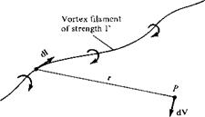
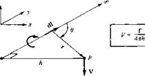
In general, a vortex filament can be curved, as shown in Figure 5.6. Here, only a portion of the filament is illustrated. The filament induces a flow field in the surrounding space. If the circulation is taken about any path enclosing the filament, a constant value Г is obtained. Hence, the strength of the vortex filament is defined as Г. Consider a directed segment of the filament dl, as shown in Figure 5.6. The radius vector from dl to an arbitrary point P in space is r. The segment dl induces a velocity at P equal to

The Vortex Filament, the Biot-Savart Law, and Helmholtz’s Theorems Подпись: [5.6]

Equation (5.5) is called the Biot-Savart law and is one of the most fundamental re­lations in the theory of inviscid, incompressible flow. Its derivation is given in more advanced books (see, e. g., Reference 9). Here, we must accept it without proof. How­ever, you might feel more comfortable if we draw an analogy with electromagnetic theory. If the vortex filament in Figure 5.6 were instead visualized as a wire carrying an electrical current /, then the magnetic field strength dB induced at point P by a segment of the wire dl with the current moving in the direction of dl is

where ц, is the permeability of the medium surrounding the wire. Equation (5.6) is identical in form to Equation (5.5). Indeed, the Biot-Savart law is a general result of potential theory, and potential theory describes electromagnetic fields as well as

The Vortex Filament, the Biot-Savart Law, and Helmholtz’s Theorems

image406

Figure 5.6 Vortex filament and illustration of the Biot-Savart law.


inviscid, incompressible flows. In fact, our use of the word “induced” in describing velocities generated by the presence of vortices, sources, etc. is a carry-over from the study of electromagnetic fields induced by electrical currents. When developing their finite-wing theory during the period 1911-1918, Prandtl and his colleagues even carried the electrical terminology over to the generation of drag, hence the term “induced” drag.

Return again to our picture of the vortex filament in Figure 5.6. Keep in mind that this single vortex filament and the associated Biot-Savart law [Equation (5.5)] are simply conceptual aerodynamic tools to be used for synthesizing more complex flows of an inviscid, incompressible fluid. They are, for all practical purposes, a solution of the governing equation for inviscid, incompressible flow—Laplace’s equation (see Section 3.7)—and, by themselves, are not of particular value. However, when a number of vortex filaments are used in conjunction with a uniform freestream, it is possible to synthesize a flow which has a practical application. The flow over a finite wing is one such example, as we will soon see.

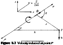
Let us apply the Biot-Savart law to a straight vortex filament of infinite length, as sketched in Figure 5.7. The strength of the filament is Г. The velocity induced at point P by the directed segment of the vortex filament dl is given by Equation (5.5). Hence, the velocity induced at P by the entire vortex filament is

image407[5.7]

From the definition of the vector cross product (see Section 2.2), the direction of V

Подпись: is downward in Figure 5.7. The magnitude of the velocity, V = |V|, is given by

image408[5.8]

image410

In Figure 5.7, let h be the perpendicular distance from point P to the vortex filament.

by an infinite, straight vortex filament.

The Vortex Filament, the Biot-Savart Law, and Helmholtz’s Theorems The Vortex Filament, the Biot-Savart Law, and Helmholtz’s Theorems

Then, from the geometry shown in Figure 5.7,

Подпись: or The Vortex Filament, the Biot-Savart Law, and Helmholtz’s Theorems Подпись: [5.10]

Substituting Equations (5.9a to c) in Equation (5.8), we have

Thus, the velocity induced at a given point P by an infinite, straight vortex filament at a perpendicular distance h from P is simply Г/2лІг, which is precisely the result given by Equation (3.105) for a point vortex in two-dimensional flow. [Note that the minus sign in Equation (3.105) does not appear in Equation (5.10); this is because V in Equation (5.10) is simply the absolute magnitude of V, and hence it is positive by definition.]

Consider the semi-infinite vortex filament shown in Figure 5.8. The filament extends from point A to oo. Point A can be considered a boundary of the flow. Let P be a point in the plane through A perpendicular to the filament. Then, by an integration similar to that above (try it yourself), the velocity induced at P by the semi-infinite vortex filament is

We use Equation (5.11) in the next section.

The great German mathematician, physicist, and physician Hermann von Helm­holtz (1821-1894) was the first to make use of the vortex filament concept in the analysis of inviscid, incompressible flow. In the process, he established several

The Vortex Filament, the Biot-Savart Law, and Helmholtz’s Theorems

z


A


The Vortex Filament, the Biot-Savart Law, and Helmholtz’s Theorems

image413

image414

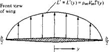
Figure 5.0 Sketch of the lift distribution along the span of a wing.

basic principles of vortex behavior which have become known as Helmholtz’s vortex theorems:

1. The strength of a vortex filament is constant along its length.

2. A vortex filament cannot end in a fluid; it must extend to the boundaries of the

fluid (which can be ±oo) or form a closed path.

We make use of these theorems in the following sections.

Finally, let us introduce the concept of lift distribution along the span of a finite wing. Consider a given spanwise location yb where the local chord is c, the local geometric angle of attack is a, and the airfoil section is a given shape. The lift per unit span at this location is L'(yj). Now consider another location vy along the span, where c, a, and the airfoil shape may be different. (Most finite wings have a variable chord, with the exception of a simple rectangular wing. Also, many wings are geometrically twisted so that a is different at different spanwise locations—so – called geometric twist. If the tip is at a lower a than the root, the wing is said to have washout; if the tip is at a higher a than the root, the wing has washin. In addition, the wings on a number of modern airplanes have different airfoil sections along the span, with different values of ac=o; Ibis is called aerodynamic twist.) Consequently, the lift per unit span at this different location, L'(y2), will, in general, be different from L'(y). Therefore, there is a distribution of lift per unit span along the wing, that is, L’ = L'{y), as sketched in Figure 5.9. In turn, the circulation is also a function of y, Г (у) = L'(y)/PoqVoo. Note from Figure 5.9 that the lift distribution goes to zero at the tips; that is because there is a pressure equalization from the bottom to the top of the wing precisely at у = —b/2 and b/2, and hence no lift is created at these points. The calculation of the lift distribution L(y) [or the circulation distriution Г (у)] is one of the central problems of finite-wing theory. It is addressed in the following sections.

In summary, we wish to calculate the induced drag, the total lift, and the lift distribution for a finite wing. This is the purpose of the remainder of this chapter.

Preface to the Third Edition

The purpose of this third edition is the same as the first two—to be read, understood, and enjoyed. Due to the extremely favorable comments from readers and users of the first two editions, virtually all of the earlier editions have been carried over intact to the third edition. Therefore, all the basic philosophy, approach, and content discussed and itemized by the author in the Preface to the First Edition is equally applicable now. Since that preface was repeated earlier, no further elaboration will be given here.

Question: What distinguishes the third edition from the first two? Answer: Much new material has been added in order to enhance and expand that covered in the earlier editions. In particular, the third edition has:

1. A series of Design Boxes scattered throughout the book. These design boxes are special sections for the purpose of discussing design aspects associated with the fundamental material covered throughout the book. These sections are literally placed in boxes to set them apart from the mainline text. Modern engineering education is placing more emphasis on design, and the design boxes in this book are in this spirit. They are a means of making the fundamental material more relevant, and making the whole process of learning aerodynamics more fun.

2. Additional sections highlighting the role of computational fluid dynamics (CFD). In the practice of modern aerodynamics, CFD has become a new “third dimen­sion” existing side-by-side with the previous classic dimensions of pure theory and pure experiment. In recognition of the growing significance of CFD, new material has been added to give the reader a broader image of aerodynamics in today’s world.

3. More material on viscous flow. Part 4 on viscous flow has been somewhat rear­ranged and expanded, and now contains two additional chapters in comparison to the previous editions. The new material includes aspects of stagnation point aerodynamic heating, engineering methods of calculation such as the reference temperature method, turbulence modeling, and expanded coverage of modern CFD Navier-Stokes solutions. However, every effort has been made to keep this material within reasonable bounds both in respect to its space and the level of its presentation.

4. Additional historical content scattered throughout the book. It is the author’s opinion that knowledge of the history of aerodynamics plays an important role in the overall education and practice of modern aerodynamics. This additional historical content simply complements the historical material already contained in the previous editions.

5. Many additional worked examples. When learning new technical material, es­pecially material of a fundamental nature as emphasized in this book, one can

never have too many examples of how the fundamentals can be applied to the solution of problems.

6. A large number of new, additional figures and illustrations. The additional ma­terial just itemized is heavily supported with visual figures. I vigorously believe that “a picture is worth a thousand words.”

7. New homework problems added to those carried over from the second edition.

Much of the new material in this third edition is motivated by my experiences over the decade that has elapsed since the second edition. In particular, the design boxes follow the objectives and philosophy that dominate my new book Aircraft Per­formance and Design, McGraw-Hill, Boston, 1999. Moreover, the feature of design boxes has recently been introduced in my new edition of Introduction to Flight, 4th ed., McGraw-Hill, Boston, 2000, and has already met with success. The importance of CFD reflected in this third edition is part of my efforts to introduce aspects of CFD into undergraduate education; my book Computational Fluid Dynamics: The Basics with Applications, McGraw-Hill, New York, 1995, is intended to provide a window into the subject of CFD at a level suitable for advanced undergraduates. Finally, the new historical notes contained here are a product of my research and maturity gained while writing A History of Aerodynamics, and Its Impact on Flying Machines, Cam­bridge University Press, New York, 1997 (hardback), 1998 (paperback). I would like to think this third edition of Fundamentals of Aerodynamics has benefited from the above experience.

All the new additions not withstanding, the main thrust of this book remains the presentation of the fundamentals of aerodynamics; the new material is simply intended to enhance and support this thrust. The book is organized along classical lines, dealing with inviscid incompressible flow, inviscid compressible flow, and viscous flow in sequence. My experience in teaching this material to undergraduates finds that it nicely divides into a two-semester course, with Parts 1 and 2 in the first semester, and Parts 3 and 4 in the second semester. Also, for the past eight years I have taught the entire book in a fast-paced, first-semester graduate course intended to introduce the fundamentals of aerodynamics to new graduate students who have not had this material as part of their undergraduate education. The book works well in such a mode.

I would like to thank the McGraw-Hill editorial staff for their excellent help in producing this book, especially Jonathan Plant and Kristen Druffner in Boston, and Kay Brimeyer in Dubuque. Also, special thanks go to my long-time friend and associate, Sue Cunningham, whose expertise as a scientific typist is beyond comparison, and who has typed all my book manuscripts for me, including this one, with great care and precision.

As a final comment, aerodynamics is a subject of intellectual beauty, composed and drawn by many great minds over the centuries. Fundamentals of Aerodynamics is intended to portray and convey this beauty. Do you feel challenged and interested by these thoughts? If so, then read on, and enjoy!

John D. Anderson, Jr.

Energy Equation

For an incompressible flow, where p is constant, the primary flow-field variables are p and V. The continuity and momentum equations obtained earlier are two equations

in terms of the two unknowns p and V. Hence, for a study of incompressible flow, the continuity and momentum equations are sufficient tools to do the job.

However, for a compressible flow, p is an additional variable, and therefore we need an additional fundamental equation to complete the system. This fundamental relation is the energy equation, to be derived in this section. In the process, two additional flow-field variables arise, namely, the internal energy e and temperature T. Additional equations must also be introduced for these variables, as will be mentioned later in this section.

The material discussed in this section is germane to the study of compressible flow. For those readers interested only in the study of incompressible flow for the time being, you may bypass this section and return to it at a later stage.

Nonlifting Flows over Arbitrary Bodies: The Numerical Source Panel Method

In this section, we return to the consideration of nonlifting flows. Recall that we have already dealt with the nonlifting flows over a semi-infinite body and a Rankine oval and both the nonlifting and the lifting flows over a circular cylinder. For those cases, we added our elementary flows in certain ways and discovered that the dividing streamlines turned out to fit the shapes of such special bodies. However, this indirect method of starting with a given combination of elementary flows and seeing what body shape comes out of it can hardly be used in a practical sense for bodies of arbitrary shape. For example, consider the airfoil in Figure 3.37. Do we know in advance the correct combination of elementary flows to synthesize the flow over this specified body? The answer is no. Rather, what we want is a direct method; that is, let us specify the shape of an arbitrary body and solve for the distribution of singularities which, in combination with a uniform stream, produce the flow over the given body. The purpose of this section is to present such a direct method, limited for the present to nonlifting flows. We consider a numerical method appropriate for solution on a high-speed digital computer. The technique is called the source panel method, which, since the late 1960s, has become a standard aerodynamic tool in industry and most research laboratories. In fact, the numerical solution of potential flows by both source and vortex panel techniques has revolutionized the analysis of low-speed flows. We return to various numerical panel techniques in Chapters 4 through 6. As a modem student of aerodynamics, it is necessary for you to become familiar with the fundamentals of such panel methods. The purpose of the present section is to introduce the basic ideas of the source panel method, which is a technique for the numerical solution of nonlifting flows over arbitrary bodies.

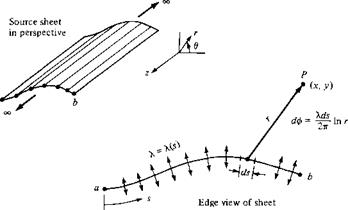
First, let us extend the concept of a source or sink introduced in Section 3.10. In that section, we dealt with a single line source, as sketched in Figure 3.21. Now imagine that we have an infinite number of such line sources side by side, where the strength of each line source is infinitesimally small. These side-by-side line sources form a source sheet, as shown in perspective in the upper left of Figure 3.38. If we look along the series of line sources (looking along the z axis in Figure 3.38), the source sheet will appear as sketched at the lower right of Figure 3.38. Here, we are looking at an edge view of the sheet; the line sources are all perpendicular to the page. Let s be the distance measured along the source sheet in the edge view. Define X = X(s) to be the source strength per unit length along s. [To keep things in perspective, recall from Section 3.10 that the strength of a single line source Л was defined as the volume flow rate per unit depth, that is, per unit length in the z direction. Typical units for Л are square meters per second or square feet per second. In turn, the strength of a source sheet A.(.v) is the volume flow rate per unit depth (in the z direction) and per unit length (in the s direction). Typical units for X are meters per second or feet per second.] Therefore, the strength of an infinitesimal portion ds

a


Figure 3.38 Source sheet.


image276

of the sheet, as shown in Figure 3.38, is Xds. This small section of the source sheet can be treated as a distinct source of strength X ds. Now consider point P in the flow, located a distance r from ds the cartesian coordinates of P are (x, у). The small section of the source sheet of strength X ds induces an infinitesimally small potential d<p at point P. From Equation (3.67), d<p is given by

Подпись: 2n [3.141]

Подпись: ф(х,у)= • lnr image278

The complete velocity potential at point P, induced by the entire source sheet from a to b, is obtained by integrating Equation (3.141):

Note that, in general, X(s) can change from positive to negative along the sheet; that is, the “source” sheet is really a combination of line sources and line sinks.

Next, consider a given body of arbitrary shape in a flow with freestream velocity Vqo, as shown in Figure 3.39. Let us cover the surface of the prescribed body with a source sheet, where the strength X(s) varies in such a fashion that the combined action of the uniform flow and the source sheet makes the airfoil surface a streamline of the flow. Our problem now becomes one of finding the appropriate X(s). The solution of this problem is carried out numerically, as follows.

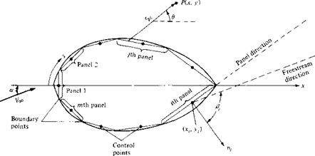
Let us approximate the source sheet by a series of straight panels, as shown in Figure 3.40. Moreover, let the source strength X per unit length be constant over a given panel, but allow it to vary from one panel to the next. That is, if there are a total of n panels, the source panel strengths per unit length are X ], X2,…, Xj…, Xn. These panel strengths are unknown; the main thrust of the panel technique is to solve for Xj, j — 1 to n, such that the body surface becomes a streamline of the flow. This boundary condition is imposed numerically by defining the midpoint of each panel

image279

Uniform flow Source sheet on surface of body, with (s) calculated to make the body surface a streamline


image280

Flow over the body of given shape


Figure 3.39


Superposition of a uniform flow and a source sheet on a body of given shape, to produce the flow over the body.


Figure 3.40


Source panel distribution over the surface of a body of arbitrary shape.


image281

Nonlifting Flows over Arbitrary Bodies: The Numerical Source Panel Method

to be a control point and by determining the kj ’s such that the normal component of the flow velocity is zero at each control point. Let us now quantify this strategy.

Let P be a point located at (x, y) in the flow, and let r[4 be the distance from any point on the / th panel to P, as shown in Figure 3.40. The velocity potential induced at P due to the y’th panel A<f>j is, from Equation (3.142),

Equation (3.146) is physically the contribution of all the panels to the potential at the control point of the ith panel.

Recall that the boundary condition is applied at the control points; that is, the normal component of the flow velocity is zero at the control points. To evaluate this component, first consider the component of freestream velocity perpendicular to the panel. Let n, be the unit vector normal to the ith panel, directed out of the body, as shown in Figure 3.40. Also, note that the slope of the ith panel is (dy/dx)j. In general, the freestream velocity will be at some incidence angle a to the x axis, as shown in Figure 3.40. Therefore, inspection of the geometry of Figure 3.40 reveals that the component of Voo normal to the ith panel is

Подпись: [3.148]koo, n — Vco • n, — Voo CDS

where Pi is the angle between and n, . Note that V7^ ,, is positive when directed away from the body, and negative when directed toward the body.

The normal component of velocity induced at (x,, y,) by the source panels is, from Equation (3.146),

= — [ф(Хі, уі)] [3.14P]

drii

where the derivative is taken in the direction of the outward unit normal vector, and hence, again, V„ is positive when directed away from the body. When the derivative in Equation (3.149) is carried out, appears in the denominator. Consequently, a singular point arises on the ith panel because when j — i, at the control point itself rtj = 0. It can be shown that when j = і, the contribution to the derivative is simply

A.,-/2. Hence, Equation (3.149) combined with Equation (3.146) becomes

ЧФ1)

In Equation (3.150), the first term A,/2 is the normal velocity induced at the і th control point by the г th panel itself, and the summation is the normal velocity induced at the (th control point by all the other panels.

The normal component of the flow velocity at the г th control point is the sum of that due to the freestream [Equation (3.148)] and that due to the source panels [Equation (3.150)]. The boundary condition states that this sum must be zero:

Eoo," + vn = 0 [3.151]

Substituting Equations (3.148) and (3.150) into (3.151), we obtain

A. ■ n к’ С d

Т + (lnru)dsi + Voccosft = 0 [3.152]

2 7^ 2tt Jj dn, J

<//l)

Equation (3.152) is the crux of the source panel method. The values of the integrals in Equation (3.152) depend simply on the panel geometry; they are not properties of the flow. Let Ijj be the value of this integral when the control point is on the (th panel and the integral is over the jth panel. Then Equation (3.152) can be written as

к’ П к ■

j + U-i + V°° C0S ft = 0 [3.153]

J = [

U*i>

Equation (3.153) is a linear algebraic equation with n unknowns A,, A2,…, A„. It represents the flow boundary condition evaluated at the control point of the (th panel. Now apply the boundary condition to the control points of all the panels; that is, in Equation (3.153), let ( = 1,2, ,n. The results will be a system of n linear algebraic

equations with n unknowns (Aj, A2, …, A„), which can be solved simultaneously by conventional numerical methods.

Look what has happened! After solving the system of equation represented by Equation (3.153) with і = 1, 2, …, n, we now have the distribution of source panel strengths which, in an appropriate fashion, cause the body surface in Figure 3.40 to be a streamline of the flow. This approximation can be made more accurate by increasing the number of panels, hence more closely representing the source sheet of continuously varying strength A(.v) shown in Figure 3.39. Indeed, the accuracy of the source panel method is amazingly good; a circular cylinder can be accurately represented by as few as 8 panels, and most airfoil shapes, by 50 to 100 panels. (For an airfoil, it is desirable to cover the leading-edge region with a number of small panels to represent accurately the rapid surface curvature and to use larger panels over the relatively flat portions of the body. Note that, in general, all the panels in Figure 3.40 can be different lengths.)

Once the A; ’s (i = 1,2,…, n) are obtained, the velocity tangent to the surface at each control point can be calculated as follows. Let s be the distance along the body surface, measured positive from front to rear, as shown in Figure 3.40. The component of freestream velocity tangent to the surface is

Voo, s = VooSinft [3.154]

The tangential velocity V, at the control point of the /th panel induced by all the panels is obtained by differentiating Equation (3.146) with respect to s:

30 Ая, г a r, = 13,511

7 = 1 J

[The tangential velocity on a flat source panel induced by the panel itself is zero; hence, in Equation (3.155), the term corresponding to j = і is zero. This is easily seen by intuition, because the panel can only emit volume flow from its surface in a direction perpendicular to the panel itself.] The total surface velocity at the г th control point Vj is the sum of the contribution from the freestream [Equation (3.154)] and from the source panels [Equation (3.155)]:

n X • C 3

Vi = Уоо, і + vs = Loosing + —(Inrij)dsj [3.156]

7 = 1 j

In turn, the pressure coefficient at the г th control point is obtained from Equation (3.38):

Cw -1′

In this fashion, the source panel method gives the pressure distribution over the surface of a nonlifting body of arbitrary shape.

When you carry out a source panel solution as described above, the accuracy of your results can be tested as follows. Let Sj be the length of the yth panel. Recall that Xj is the strength of the у th panel per unit length. Hence, the strength of the yth panel itself is X, Sj. For a closed body, such as in Figure 3.40, the sum of all the source and sink strengths must be zero, or else the body itself would be adding or absorbing mass from the flow—an impossible situation for the case we are considering here. Hence, the values of the Xj’s obtained above should obey the relation

n

J2>-jSj= о [3.157]

7 = 1

Equation (3.157) provides an independent check on the accuracy of the numerical results.

Example 3.12

Calculate the pressure coefficient distribution around a circular cylinder using the source panel technique.

Solution

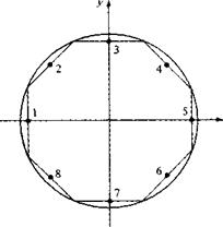
We choose to cover the body with eight panels of equal length, as shown in Figure 3.41. This choice is arbitrary; however, experience has shown that, for the case of a circular cylinder, the arrangement shown in Figure 3.41 provides sufficient accuracy. The panels are numbered from 1 to 8, and the control points are shown by the dots in the center of each panel.

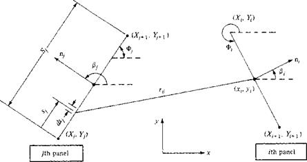
Let us evaluate the integrals which appear in Equation (3.153). Consider Figure 3.42, which illustrates two arbitrary chosen panels. In Figure 3.42, (x,. y,) are the coordinates of the

image283

Figure 3.41 Source panel distribution around a circular cylinder.

image284

Figure 3.42 Geometry required for the evaluation of Іц.

control point of the ith panel and (xh yj) are the running coordinates over the entire jth panel. The coordinates of the boundary points for the і th panel are (X, , Yt) and (Xi+1, F,+i); similarly, the coordinates of the boundary points for the jth panel are (Ху, У,) and (XJ+] In this

problem, Vcc is in the x direction; hence, the angles between the x axis and the unit vectors n, and itj are ft and ft, respectively. Note that, in general, both ft and ft vary from 0 to 2л Recall that the integral ft; is evaluated at the (th control point and the integral is taken over the complete jth panel:

Nonlifting Flows over Arbitrary Bodies: The Numerical Source Panel Method

[3.158]


r4 =•/(■*(- Xj)2 + (yf – Уі)1

9 , 1 drtj

-—(In Лу) = — T—

orii r(j drii

= — ^[(a-( – Xjf + (Уі – уj)2r’/2

nj 2

dxi dy.

■ 2{Х‘-Х^+2(У‘-У^

9 (Xi – xj) cos ft + (у, – уj) sin ft

9 Пі(ППі)~ (x.-Xj)2 + (y.-yj)2


Since


then


or


image285

Figure 3.43 Pressure distribution over a circular cylinder; comparison of the source panel results and theory.


Substituting the values for the X’s obtained into Equation (3.157), we see that the equation is identically satisfied.

Nonlifting Flows over Arbitrary Bodies: The Numerical Source Panel Method Nonlifting Flows over Arbitrary Bodies: The Numerical Source Panel Method Подпись: [3.165]

The velocity at the control point of the ith panel can be obtained from Equation (3.156). In that equation, the integral over the jth panel is a geometric quantity which is evaluated in a similar manner as before. The result is

image286

With the integrals in Equation (3.156) evaluated by Equation (3.165), and with the values for 7-і, 7-2,. • •, 7.8 obtained above inserted into Equation (3.156), we obtain the velocities Vi, V2,…, Vs. In turn, the pressure coefficients Cp 1, Cp>2,…, Cp, g are obtained directly from

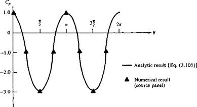
Results for the pressure coefficients obtained from this calculation are compared with the exact analytical result, Equation (3.101) in Figure 3.43. Amazingly enough, in spite of the relatively crude paneling shown in Figure 3.41, the numerical pressure coefficient results are excellent.

Three-Dimensional Source

Return to Laplace’s equation written in spherical coordinates, as (3.43). Consider the velocity potential given by

given by Equation

C

ф =——

r

[6.1]

where C is a constant and r is the radial coordinate from the origin. Equation (6.1) satisfies Equation (3.43), and hence it describes a physically possible incompressible, irrotational three-dimensional flow. Combining Equation (6.1) with the definition of the gradient in spherical coordinates, Equation (2.18), we obtain

V = V0 =

rL

[6.2]

In terms of the velocity components, we have

C

V’ = ~ r1

[6.3a]

■ о

II

s?

[6.3b]

II

О

[6.3c]

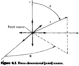
Clearly, Equation (6.2), or Equations (6.3a to c), describes a flow with straight stream­lines emanating from the origin, as sketched in Figure 6.1. Moreover, from Equation

(6.2) or (6.3a), the velocity varies inversely as the square of the distance from the origin. Such a flow is defined as a three-dimensional source. Sometimes it is called

Подпись: Figure 6.1 Three-dimensional (point) source.

simply a point source, in contrast to the two-dimensional line source discussed in Section 3.10.

Подпись: Mass flow Подпись: pV-dS

To evaluate the constant C in Equation (6.3a), consider a sphere of radius r and surface S centered at the origin. From Equation (2.46), the mass flow across the surface of this sphere is

Подпись: A = Подпись: V • dS Подпись: [6.4]

Hence, the volume flow, denoted by A., is

On the surface of the sphere, the velocity is a constant value equal to Vr = С/г2 and is normal to the surface. Hence, Equation (6.4) becomes

Подпись: A =C 7

—г 4тсг2 = 4лС rz

Подпись:TT A

Hence, C = —

47Г

Three-Dimensional Source Подпись: [6.6]

Substituting Equation (6.5) into (6.3a), we find

Compare Equation (6.6) with its counterpart for a two-dimensional source given by Equation (3.62). Note that the three-dimensional effect is to cause an inverse r – squared variation and that the quantity 4л appears rather than 2л. Also, substituting

Подпись: X ф = A nr Подпись: [6.7]

Equation (6.5) into (6.1), we obtain, for a point source,

In the above equations, X is defined as the strength of the source. When X is a negative quantity, we have a point sink.

Incompressible Versus Compressible Flows

A flow in which the density p is constant is called incompressible. In contrast, a flow where the density is variable is called compressible. A more precise definition of compressibility will be given in Chapter 7. For our purposes here, we will simply note that all flows, to a greater or lesser extent, are compressible; truly incompressible flow, where the density is precisely constant, does not occur in nature. However, analogous to our discussion of inviscid flow, there are a number of aerodynamic problems that can be modeled as being incompressible without any detrimental loss of accuracy. For example, the flow of homogeneous liquids is treated as incompressible, and hence most problems involving hydrodynamics assume p = constant. Also, the flow of gases at a low Mach number is essentially incompressible; for M < 0.3, it is always safe to assume p = constant. (We will prove this in Chapter 8.) This was the flight regime of all airplanes from the Wright brothers’ first flight in 1903 to just prior to World War II. It is still the flight regime of most small, general aviation aircraft of today. Hence, there exists a large bulk of aerodynamic experimental and theoretical data for incompressible flows. Such flows are the subject of Chapters 3 to 6. On the other hand, high-speed flow (near Mach 1 and above) must be treated as compressible; for such flows p can vary over wide latitudes. Compressible flow is the subject of Chapters 7 to 14.