Category NEW DESIGN CONCEPTS FOR HIGH SPEED AIR TRANSPORT

Fictitious gas for a flow control concept

Bom from originally a mathematically motivated mampulatum to solve the mixed type differen­tial equations modelling shock-free transonic flow, the definition of modified gas properties may be considered as a physical equivalent to this theoretical approach. Rhcograph models for 2D flow for an analytical extension of the subsonic (elliptic type) problem into the supersonic do­main in order to pose and solve a boundary value problem for shock-free airfoil flow results in a modified equation of state as part of the Euler or Navier Stokes equations. Solving such mod­ified equations in direct 2D or 3D space for airfoils, wings or full aircraft configurations will therefore result in supercritical shock-free flow where the domain with velocities higher than the critical value is of a subsonic nature with locally “fictitious” properties, i. e. no practical realiza­tion of this flow is proposed so far

Before this approach is explained as just the first part of a systematic and practical design method, it may be noted (Figure 41), that an interpretation of the fictitious gas as an ideal gas with pressure-controlled energy removal within the local supercritical domain lays ground for an interpretation as a thermodynamic flow control method for obtaining higher aerodynamic efficiency of given configurations. This Figure illustrates this for a thick wing section in tran­sonic flow: Entropy contours and wake profiles at a control surface behind the airfoil allow to compare drag for these flows. Including viscous drag, aerodynamic efficiency (lift over drag) of the controlled airfoil flow is about 50% higher than for an uncontrolled flow. The remaining problem, of course, is the need to remove energy depending on the local pressure p < p* within the supercritical domain, as indicated in Figure 41 by the region w ith local entropy s < 0. rela­tive to upstream values.

Gasdynamic manipulations for design purposes

The basic differential equations for compressible flow to be solved with numerical methods for practically interesting aerodynamic applications are the Reynolds-averaged Navier-Stokes equa­tions Neglecting viscous effects reduces this system of equations to the Euler equations. Gasdy – namic phenomena such as shock waves in a flow field arc simulated with sufficient accuracy by numerical algorithms for the latter inviscid model equations. Consequently, an inviscid flow de­sign approach makes use of the Euler equations in suitable ways to help finding flows with re­duced or vanishing shock waves. Techniques developed for shock wave control arc then implemented successfully also in the Navier-Stokes equations. In this paragraph, a special ap­proach to control shock wave strength is outlined: Tlie Fictitious Gas (FG) method. This method was already developed when numerical algorithms to solve the compressible potential flow dif­ferential equations resulted in the first applied aerodynamic analysis computer programs (89). In the meantime, the increased requirements for higher aerodynamic efficiency of an aircraft seems to justify a rev iew of the theoretical ptytential of the FG method. In the following, first the purely "fictitious” part, i. c. the abstract mathematical model for the method is explained with the atm of a practical application. Second, the most recent results of classical shock-free flow construc­tion by the FG method is illustrated and third, practical methods for rapid aerodynamic design derived from these approaches, using both the knowledge base for phenomena modelling and proven CFD axles is outlined.

Figure 41 Comparison of viscous transonic flow (M„ • 0.7, Re = 20 Mill., c, = 0.6) past u given airfoil without (above, a) and with (below, b) flow control, carried out by energy removal within the supercritical domain. Entropy level isofringes and wake profile at the trailing edge indicate drug reduction of 35%.

Swept wings with subsonic leading edges

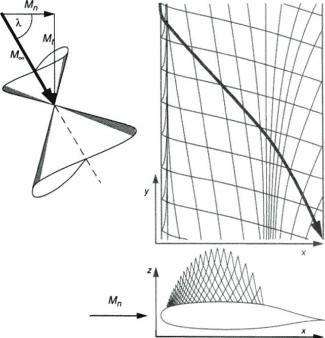
It is a well-known design principle to use two-dimensional airfoil flows in lower tran­sonic or completely subsonic Mach number flows for the definition of swept wings in higher transonic or even supersonic Mach number flows. A shock-free transonic airfoil flow com­pletely defines a family of 3D infinite wing flows yawed to upstream flow conditions with higher Mach numbers, with a relation between 2D and 3D Mach numbers Мд> * M^fcosfX), where Mjjj = M„ for the wing and Mjd = MN. the airfoil design Mach number and 3D Mach number component normal to the wing. Figure 40 shows an example, with characteristics evalu­ated for both 2D and 3D flow. The latter arc 3D Mach conoid traces and mark regions of influ­ence and dependence; a coalescence of characteristics in the locution of 2D shock-free recompression illustrates the possibility of accumulative perturbation effects from distant span – wise locations in this area.

Figure 40 Using a 17% thick supercritical shock-free airfoil flow, <Mn s 0.707, C| * 0.6)

to define an infinite swept wing, = 60°. shock-free at M. = 1.414, CL = 0.15. Characteristics evaluation in supercritical airfoil flow and on swept wing upper surface.

Characteristics in 2D and in 3D How

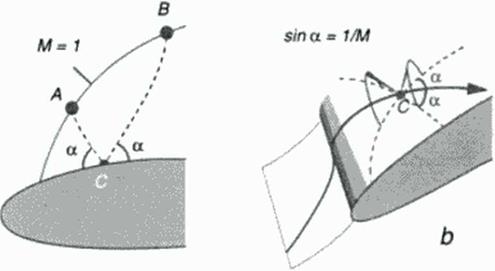
In supersonic flow. Mach waves or characteristics are appearing as straight orthogonal lines ^ = t+s. П * t-s »n the s. i rheograph plane. Basic system (I). or It’s full compressible potential flow extension, see Ref. (86J. maps these families of lines to 2D curses in the physical plane, within the domain of supersonic local Mach numbers Figure 39 shows a 2D airfoil flow clement w ith a chosen surface point C and both characteristics AC and CB intersecting it inclined to the flow direction with an angle a * arcsint 1/M): regions of influence from upstream and dependence to downstream arc defined this way. For given flow data w ithin the sonic line segment AB the so­lution for supersonic flow is completely determined w ithin the triangle ABC This is the basis for the 2D inverse method of characteristics (78) allowing the construction of a supersonic flow pat­tern.

Figure 39 Characteristics (Mach waves) in transonic 2D Пон (aI and 3D flow (b).

In 3D flow, both families of characteristics are Mach – conoid intersections, as illus­trated in Figure 39b for a 3D wing element. They may intersect the sonic surface far away from surface location C and will not form closed domains comparable to the 2D sonic line interval AB. Mathematically an ill-posed problem, the inverse integration of 3D local supersonic flow fields with a potential flow cross marching technique nevertheless gave very satisfactory results for transonic wings (87). (88). A more recent application for the design of supersonic wings, using an inverse version of the 3D Euler equations is outlined in the next book chapter.

From Flow Construction to Aerodynamic Design

7.3.1 Flow pattern integration from given sonic locus or shock

In the rheograph plane subsonic flow is separated from supersonic flow by the sonic locus, where U(s. t) = 0. Solving the model equations (64M67) for a transonic problem, where both types of flow (U < 0. U > 0) occur, therefore requires applying separate solution methods for both parts, with the need to have common data at the line U(s. t) = 0. For plane (p, = 0). transonic (p2 = 1/3) flow, solution to (64)-<65) is the first step, because it is decoupled from (66M67). Choosing U = s, V = t is just the simplest solution, without loosing generality of subsequently finding solu­tions X = X(s. t). Y a Y(s, t) to the linear system (66Ц67) in a second step. Creating a solution to both the subsonic pan and the supersonic part now requires prescribing data X*(t). Y*(t) along s = 0. This data prescription is equivalent to defining the sonic line and a distribution of flow directions along it in physical space (X. Y) The data are used as part of the boundary conditions to an elliptic problem in the subsonic domain (s £ 0» and as initial data for a hyperbolic problem in the supersonic domain (s 2 0). Figure 38a shows the direction of integrating the local super­sonic flow pattern: with the complete sonic line given, supersonic marching must be performed in a cross-flow direction, leaving die given sonic line unchanged and obtaining an arc of the sur­face geometry as a result. This way an inverse approach results in the goal of obtaining a surface geometry compatible with a strongly controlled sonic line. In the 1970’s, techniques were devel­oped to design transonic airfoils using this concept (84). A rheoelectric analog computer’ pro­vided a very educational tool to understand also the background of Garabcdian’s method of complex characteristics to design shock-free airfoils (85). which was a mathematically elegant method but did not provide a lasting engineering know ledge base because of its complexity

It is only a small step to a quite different application of this inverse concept for local flow field integration: Replacing the sonic locus by an oblique shock wave, geometrically defined in a given (uniform or nonuniform) upstream supersonic flow, defines also post shock flow data as initial conditions for a cross-flow integration toward a contour streamline compati­ble w ith the oblique shock wave. Figure 38b shows this approach: a segment of supersonic flow bounded by the given shock wave, the resulting contour and an open exit illustrate ЫчЬ the commonality and the difference with the transonic design approach. Figure 38a. The supersonic application will be described in more detail in the next book chapter, while the following para­graphs of this chapter arc devoted to numerical design methods based on the transonic applica­tion.

Figure 38 Inverse design concepts in transonic and in supersonic flow.

Shock – sonic surface interaction in 3D flow

Compared to the rich variety of analytical models in plane transonic flow, our knowledge of local transonic phenomena in three-dimensional flow is much more limited. Equations (64H67) allow a construction of axisymmetric near sonic flow models, but the system is stilt weakly nonlinear so that basic solutions (781 may not be superimposed. Fully 3D flow docs not permit a hodo – graph-type mapping, our knowledge base is restricted to experiments and evaluation of refined numerical analysis results. For design, a detailed knowledge base is needed to prepare a physi­cally consistent and mathematically well-posed input for a reasonable numerical simulation. In­verse design methods arc aimed at finding configurations with prescribed pressure distributions. This is a very attractive approach for practical design but inconsistencies between geometrical constraints and desired flow quality may occur: Ideal design goals may ignore the fact that una­voidable shock waves will accompany the envisioned flow patterns.

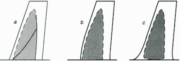
An example is the design of a swept transonic w ing fixed to a wall or a fuselage w ith­out any fillet: the non-orthogonal comer angles between wing and sidewall do not allow for a smooth pressure distribution in the sonic expansion and rccompression domain. Oblique shocks fonn and travel into the spanwise direction, eventually coalescing to stronger rccompression waves, see Figure 37a Only a locally unswept surface geometry can accomodate smooth expan­sion and rccompression across sonic flow conditions (Figure 37b). Another way to avoid this purely inviscid feature of the flow – and at the same time also influence viscous flow interaction favorably is the design of a fillet (Figure 37c) which provides a smooth surface without comers at the wing root. This qualitative sketch of 3D flow features is based on practical designers’ experience, supported by an extrapolation of the well-developed knowledge base for 2D flows.

Figure 37 Local supersonic domain (shaded) on wall-mounted swept wings in high subsonic Mach number flow: Oblique shock formation at wing root sonic expansion and recompression. Shock-free expansion and recompression requires locally unswept geometry (b) or fillet (c)

Local 2D flow quality and singularity models

Near sonic Beltrami equations

The potential equation for a near-sonic plane or axisymmctric flow has a particularly elegant for­mulation in variables of state or in characteristic variables (for details see Ref (78)). illustrating the formal relationship between incompressible, transonic, plane and axially symmetric potential problems: characteristic equation and compatibility relation define a system of quasi-lincar first order differential equations

V, = YP’U,

(64)

V, = jYP‘U,

(65)

Xt = UP:Y,

(66)

X, = jUP‘Y,

(67)

Here the variables (X. Y) denote the physical space and (U, V) a n<»rmalizcd pair of velocity variables, namely the Prandil-Meyer function and the flow angle. Both pairs are

dependent variables in a workspace ts, t) “Rheograph plane” w hich is identical with characteris­tic variables in supersonic flow (j=l, U>0) and their analytical continuation beyond the sonic – line where j«-1, U < 0. Exponents pt and pj have a switch function: p, =0 denotes plane 2D flow, p, ■ 1 indicates axially symmetric flow; p> = 0 results in a simple mapping of linear sub­sonic or supersonic flow while PS = 1/3 switches to transonic flow. These equations include most of the flow models described by the pioneers in theoretical transomes. in closed analytical form or. for transonic axisyntmetric flow where a weak nonlinearity persists, in a numerically very suitable form

Equations (64M67) describe a large number of educational solutions which should be kept ‘alive’ as part of the knowledge base for transonic design and phenomena analysis. Because of (64)-(67) representing a system for quasi-conformal or characteristic mapping, solu­tions may be interpreted as transformations of geometries consisting of both the boundary con­ditions and ail details of the flow, appearing as an analog flow in the rheograph plane.

Applications of mapped problems to test cases for numerical methods

In the transonic and low supersonic Mach number regime, analytical soloutions describing the local or asymptotic behavior of shock waves in the flow arc of particular interest. Like the well – known logarithmic singularity (79) for the normal shock on a curved contour, there are other sin­gular solutions for interaction of shock waves with solid boundaries or with flow phenomena near sonic conditions. Frequently, limiting cases between two known mathematical models have to be found. One such case is modelling a smooth transition from the mathematically well under­stood far field behavior of an airfoil in some flow * I to the appearance of a detached shock wave in front of it if the free stream М» slightly exceeds unity. This example was solved by a mapping to the rheograph plane (80).

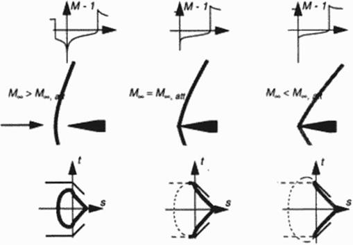
More recently a similar problem was solved by a local mapping of the 2D plane flow near the tip of a wedge ramp at precisely the attachment Mach number The limiting case

between a detached shock, normal to the flow axis, approaching the tip and an oblique shock attached to the wedge in supersonic flow (see the early experiments (81 ]>. had to be found. Fig­ure I illustrates this limiting case both in the physical plane and mapped to the rheograph plane Results arc given in (82). here it’s just worth to mention that another, new logarithmic singular­ity at the wedge tip is found from simple mapping procedures.

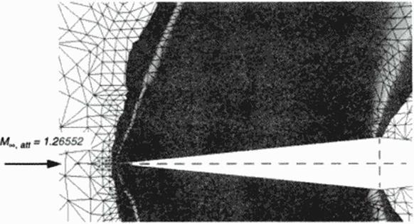
The value of such local solutions for new and rerined computational methods in fluid dynamics is evident: known local flow models represent exact solutions and refinements should give information about needed efforts to obtain such solutions numerically to a desired degree of accuracy. The wedge problem serves as a test case for an unstructured grid Euler code [83) where local grid refinements allow for a sharpening of the shock waves occurring in the flow, see Figure 36.

Figure 35 Understanding shock attachment / detachment to a wedge: Rheograph mapping and shock relations transform problem to an analog flow detail and conformal mapping case. From above: Aeial and surface Mach number distribution with changing wedge tip singularities; shock detachment, limiting case and shock attachment; shock polar growing and intersecting wedge boundary condition for increased Mach number.

Figure 36 Numerical simulation of shock attaching to a wedge (slope 1:10 ). Simulation

with unstructured grid Euler code, grid adaptation near shock wave, isobars visualization

Control of Sonic Surfaces and Shock Waves

In a time long before the arrival of the digital computer, the model equations for compressible flow were derived. Since then, we know the Reynolds-averaged Navier-Stokes for the full prob­lem, the Euler equations for their inviscid simplification and the Potential equation for a further simplification to isoenergctic flows. The latter extended the classical knowledge base of hydro­dynamics into the compressible flow regime. A necessity to find solutions to these equations then led to several attempts to transform them, for instance to reduce the formidable difficulties stem­ming from the nonlinearity of the potential equation. In 2D flow, the hodograph transformation leads to an inversion of the problem, trading linear equations for nonlinear boundary conditions. Several mathematical methods were developed to create the first transonic airfoils. Elegant prob­lem formulations could not hide the fact that solving mapped counterparts of real world problems never became very popular with the aerospace design engineer. Nevertheless, in a time when usually only numerical discretization of complex problems is seen as the way to get deeper in­sight into flow problems, some of these mapped model equations still have some value. One form of the "near sonic" model equations was found particularly useful, because it not only gave a number of flow models for transonic phenomena in closed analytical form hut also led the way toward design principles for practical airfoils and wings.

GASDYNAMIC KNOWLEDGE BASE FOR HIGH SPEED FLOW MODELLING

H. Sobicczky

DLR German Aerospace Research Establishment, Gottingen. Germany

7.1 Introduction

This chapter is intended to illustrate a fragment of developments toward systematic high speed design, that is here aerodynamics in the regime of transonic and supersonic Mach numbers. The purpose is to show the modelling background of a combination of gasdynamics and geometry in the development of modem software for aerodynamic design in the virtual environment of per­sonal and workstation computers. Here it is not intended to once more derive the basics for algo­rithm development in numerical simulation (CFD): only a simplified model of the basic equations is briefly mentioned because they paved the way to a better understanding of local flow phenomena, or as a consequence, of the requirements for detailed shaping of surface geometry in order to control local mviscid flow phenomena. In (he transonic as well as in the supersonic regime, theve phenomena are dominated by the interaction of surface geometry and surfaces within the How field, for instance the boundary between locally subsonic and locally supersonic flow These sonic surfaces, but also shock wave surfaces may be seen as part of the complete geometry set consisting of configuration and important flow features under design conditions. Motivation of this contribution is therefore to explain ihc gasdynamic background of some prac­tical geometry tools for aerodynamic design, which take into account sonic and shock surfaces as part of the boundary conditions. Building on the pioneering basics of Gudcriey [76] and Os – watitsch (77). the ideas underlying the outlined concepts have been developed within the author’s past theoretical work in transonics at DLR in Gottingen.

New Configuration Types

In the past, unknown configuration types mostly delivered some surprises during their flight tests: so called "unknowns", because new. unknown physical effects were detected, and “known unknowns", because phy sics were known in principle, but not respected because of the negligi­ble influence of those effects on the older, known configurations. And we have to expect new "known and unknown" surprises with new configurations. Therefore, certification of new con­figurations and related technologies like

• Oblique Flying Wing aircraft (OFW)

• extremely flexible aircraft

• flutter sensitive aircraft

• artificial flutter supression

• supersonic laminar flow technology

• artificial view

probably will require demonstration of safe operation in a flying demonstrator. To accelerate certification, careful testing of a demonstrator aircraft with mature technology is absolutely necessary To skip this step will most certainly turn out to be much more expensive and time consuming. (Although, there is a high probability that pennywise decision makers will not miss the opportunity to waste billions of $$…).

6.2 Conclusion

be applicable for civil aviation, these technologies must be certified. But even certification itself will require some special new certification technologies To forget for this part will eventually coet additional time and money, although humans and ibig) companies often prefer this route which delays the known necessary, but inconvenient decisions.