Category FLUID-DYNAMIC LIFT

CHARACTERISTICS OF SPOILERS

Definition. A spoiler is basically a device that “spoils” the flow about a wing section (or possibly about a tail – surface) in such a manner that a lift differential is pro­duced. Under certain conditions (when placed at the pres­sure side) such devices also produce lift, however, and their characteristics then resemble those of ordinary ailer­on flaps. The distinction between the two types of control thus seems to depend upon the fact whether or not spoiling of the flow pattern is an intended and primary or necessary effect of the device (12).

Mechanism. It is explained in Chapter II how circulation around an airfoil is reduced by friction and boundary – layer displacement. When enlarging the B’layer thickness at the suction side or when replacing that layer by a “wake” behind some obstruction such as a spoiler, lift is further reduced. It follows from this mechanism:

a) that spoilers can most efficiently be applied at the suction (upper) side

b) that effectiveness is highest when placing the spoiler at or near the point of maximum local velocity or mini­mum pressure

c) that the spoiler effectiveness increases with the lift coefficient.

The effectiveness increases approximately in proportion to the height of the spoiler flap. The lift differential produced in thin (t/c := 4 or 6%) and straight foil sections is in the order of

– ACL =(3 or 4) h/c (20)

It may thus seem to be possible to use a spoiler, for example, in a horizontal tail surface, and they have indeed been used (or proposed to be used) in the control surfaces of missiles (possibly for reasons other than aerodynamic). We will see, however, that spoilers can be used more profitably in combination with round-nosed (15) and cambered foil sections that exhibit trailing edge stalling as in wings, and they are then used for lateral control.

CHARACTERISTICS OF SPOILERS

103

Подпись: -80 -60 -40 -20 CCHARACTERISTICS OF SPOILERSПодпись:As a consequence, the spoiler can be the most effective means of lateral airplane control at higher lift coefficients (i. e. at low flying speeds) where conventional ailerons have the tendency to fail (a) because of separation from their suction side, (b) because of rolling moment (in foot-pounds) being proportional to V2, where V = speed of the airplane.

Thin Foil Sections. As explained in Chapters II and IV there are two basic types of foil sections:

a) essentially straight and thin sections with leading-edge stalling

b) round-nose and more or less cambered sections with trailing-edge stalling.

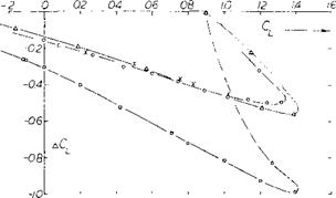
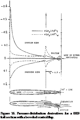
Figure 16 presents the lift effectiveness of a “spoiler” flap (simulated by a triangular ridge) extended from the upper side of a thin and straight foil section. The lift differential produced is:

a) comparatively small

b) nearly independent of the angle of attack

c) comparatively independent of location along chord.

CHARACTERISTICS OF SPOILERS

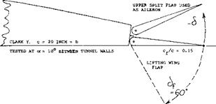
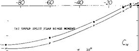
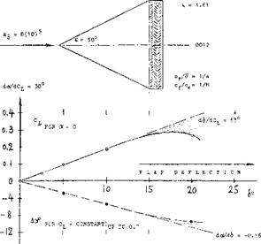
Figure 15. Double split flap arrangement, combining a lifting flap with an upper-side lateral control flap, tested (7,k) between tunnel walls.

(15) Spoilers used in thin and straight foil sections:

(a) Hammond, On 4 and 6% Foils, NACA RM L56F20.

(b) Groom, Pressure Distributions, NACA RM L58B05.

Solid Spoiler Flaps. The simplest design of a spoiler is a split-type flap, deflected from the upper side of a wing. Solid flaps of this kind have several shortcomings, how­ever:

a) their influence upon lift as a function of deflection, develops in a continuous manner.

b) they are likely to cause vibration and buffeting.

c) they have hinge moments of appreciable, if not consid­erable, magnitude.

d) their effectiveness is subjected to a timewise delay between their deflection and the reduction of the lift.

For practical purposes all of these shortcomings can be eliminated by using non-solid spoilers (such as grids, or preferably rake-like devices) and by extending them in the direction normal to the upper surface, from within, usu­ally along a certain arc, provided by a lever suitably hinged to the wing structure. An example of a realistic, if experimental, full-scale installation of this type is illus­trated in figure 22,c.

CHARACTERISTICS OF SPOILERS

A = 4

X = c/2 c =2.5 INCH

Figure 16. Example of a spoiler flap on the upper side of a thin and straight foil section tested (15) on a rectangular wing having an aspect ratio of 4.

Time Lag is very important if undesirable characteristic of spoilers. The change of circulation through trailing-edge displacement by means of a flap takes place without any noticeable (although yet measurable) time lag between deflection and the result in form of a lift differential. The change in flow pattern after projecting a spoiler, however, can take so much time that the reaction of the airplane is delayed objectionably. As an example, the tunnel-tested history of two particular spoilers is presented in figure 17. Fluid-dynamic time (z) is conveniently measured by the number of chord lengths traveled. That number is the non-dimensional ratio

X/c = z V/c (21)

where X = z V = distance traveled within the time z. In the case of the solid spoiler flap in figure 17,a, sudden projection (which takes X/c = 1.5 as indicated by a first arrow) even causes the lift at first to increase slightly. The flow does not separate immediately. Rather, it climbs over the obstacle which thus exhibits a camber effect remotely similar to that expected in non-viscous fluid flow. It then takes 4 chord lengths before the lift starts dropping below the original undisturbed level, and some 12 lengths before it finally reaches the terminal lower level. The airplane response time to a lateral control force will be added to the time lag of the spoiler, thus causing a considerable delay to the desired control correction. Such a delay will also be an irritation to the pilot through the lack of tightness in the control system. As a consequence, the danger of overcontrolling is very great by too much con­trol-stick or – wheel deflection after the original deflection did not produce any

Rake-Type Spoiler. Measured time-lag data from a number of sources have been assembled in figure 18. Conventional ailerons are included for comparison. It is seen that the delays A and B, as defined in the tabulation, are roughly as follows:

in conventional ailerons A = О В = 5

for solid spoiler plates A = 7 В = 20

for rake-type spoilers A = 2 В = 7

The improvement due to ventilation of the space behind the spoiler, as in the rake-type, is very considerable.

TYPE OF SPOILER A В z (sec)

solid, flight test

(9, b)

6

26

0.3

solid, wind tunnel

(17,b)

10

19

0.5

solid, flight test

(17,f)

7

14

0.3

solid, wind tunnel

(17,b)

7

17

0.3

screen, wind tunnel

(17,b)

3

12

0.1

saw-tooth, flight test

(9, b)

3

18

0.1

perforated, wind tunnel

(17,b)

5

12

0.2

ditto, ventilated

(17,b)

2

8

0.1

solid in water tunnel

(17,c)

4

12

0.3

ditto, but rake type

(17,c)

1.5

7

0.1

slot-lip aileron

(9, e)

1

11

conventional aileron

(17,b)

0

5

0

ditto (in wind tunnel)

(17,b)

0.6

8

ditto, flight test

(17,f)

0

5

0

ditto, flight test

(9, e)

0

4

0

ditto, flight test

(9, b)

0

5

0

A and В indicate chord lengths traveled, before lift reduction begins (A) and before the terminal reduced level of lift is reached (B). The time "2,11 represents the delay corresponding to A, under assumed landing conditions where V л 140 ft/sec (^80 kts) and for c A*7 ft; hence "z" = (7/140) A = A/20.

Подпись: 30°CHARACTERISTICS OF SPOILERS

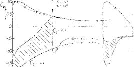
The pressure distribution around a foil section (in the center of a low-aspect-ratio rectangular wing model) is presented in figure 19 without, and in the presence of, a rake-type spoiler at the location as shown. The lift differ­ential produced (ACl = —0.5) corresponds primarily to a reduction of the negative amount (suction) of the pressure coefficient at the suction side, ahead of the spoiler, in the order of ACp = 1. In the presence of the spoiler, circula­tion is evidently appreciably reduced. A considerably en­larged boundary layer springs from the spoiler. Disregard­ing the trailing-edge flap (to be discussed later), the suc­tion-side flow is not separated, however.

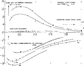
Chordwise Location. Figure 20 presents effectiveness as well as time lag of spoilers as a function of their chordwise location. As mentioned before, effectiveness (measured in the form of lift reduction ACL from CL0 = 1, produced by full spoiler extension) increases as the spoiling device is moved forward along the foil chord. Maximum effect is obtained between X/c = 0.2 and 0.3, and that effect can be appreciably higher than that of an aileron at the trailing edge. The time lag (as in the upper part of figure 20) also increases as the spoiler is moved forward. Time lag can be said to be approximately proportional to effec­tiveness. Disregarding a lesser influence of the magnitude of the original lift coefficient (at which the spoiler is used), the total delays as listed in figure 18 and as tested elsewhere, may be approximated by

X/c = к ACL (22)

where к = (x/c)/ACl has roughly values as follows:

к = 24 for solid-plate spoilers

= 8 for rake-type spoilers

= 6 for conventional ailerons.

The final delay can thus considerably be reduced by ventilation across the spoiler element.

Figure 18. Tabulation of data from various sources; indicating the lag of time between projection of a spoiler and the reduction of lift eventually caused by the spoiler.

CHARACTERISTICS OF SPOILERS

2.51Ю)6

c = 2.3 ft

CHARACTERISTICS OF SPOILERS

-20]

Figure 19. Pressure distribution around the mid-span section of a high lift rectangular wing model without and with a “rake” type spoiler extended from the upper side. (17,c).

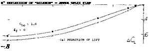
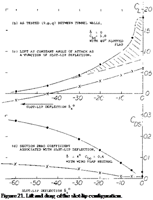
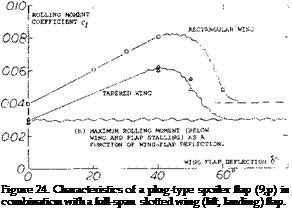
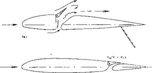
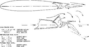
Slot-Lip Aileron. Ventilation can also be obtained by opening some kind of duct leading from the wing’s pres­sure side to behind the spoiler. In the so-called plug aileron, see figure 24, a ventilating slot is opened when the plug-shaped spoiler plate is projected from the upper surface. Another way of opening a slot is as in the original slot-lip aileron, an example of which is shown in figure 21,a. Effectiveness of this configuration is high; the time lag (see in figure 18) is considerably reduced. However, the duct leading through the wing is not very desirable and the drag added by the opening in the lower side (if left uncovered) reduces the efficiency of the wing. In an advanced form, as in part b of the illustration, the space ahead of a slotted wing flap is conveniently utilized. Results of slot-lip tests are as follows (see figure 21 ,c):

a) At very small deflection angles the slot lip has charac­teristics similar to, but poorer than those of, an ordi­nary aileron, as there may be a 5 or 10° dead range of deflection.

b) Upon exceeding a comparatively small upward deflec­tion the slot lip causes the flow to break away from the upper side of the landing flap (if deflected), and the slot lip has the functions and characteristics as a true spoiler.

c) Separation as under (b) must be expected to take place suddenly, say at 6 = —5°.

d) Effectiveness is much higher for 60° flap deflection than for neutral position.

e) Hinge moments are irregular, particularly for neutral wing-flap position because of the separation as under

(c) .

f) Drag increases with upward slot-lip deflection in a manner similar to that of the split-flap aileron de­scribed in a preceding section, thus providing a desir­able positive component of yawing moment, see part

(d) of figure 21.

In conclusion, this type of slot-lip aileron (as other spoiler types located near the trailing edge) is found to be suffi­ciently effective in combination with a deflected wing flap. It seems to be unsatisfactory, however, without such deflection.

CHARACTERISTICS OF SPOILERS

CHARACTERISTICS OF SPOILERS

Figure 21. Two versions of the slot-lip spoiler (9).

a) Original slot-lip configuration (9,e, h).

b) Combination with slotted wing flap.

c) Lift coefficient of (b) as a function of slot-lip deflection.

d) Section drag coefficient associated with slot-lip deflection.
CHARACTERISTICS OF SPOILERS
Подпись: O NACA (18,a) ■ Fi-156 (17,b) FLIGHT TEST, SOLID h = 5* • NACA (18,a) SLOT-LIP AILERONS Д RAKES (17,c) IN WATER TUNNEL X NACA (9,1) a JONES (17,e) SOLID SPOILER h = 5% c 0 NACA (9,h) SOLID h = (2.5 and 5)% c

Подпись:

Figure 20. Characteristics of suction-side spoilers as a function of their location along the foil-section chord.

a) Time lag measured to the point where the reduced lift level is reached.

b) Effectiveness obtained for an original undisturbed lift coeffi­cient CLO = 1.0.

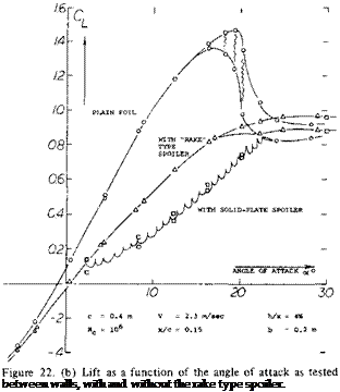
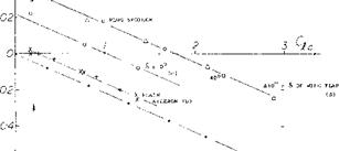
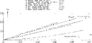
Подпись:Effectiveness as a Function of Lift. The lift coefficient of a foil section is presented in figure 22 without and with a rake-type spoiler projected from the upper side. It is seen that the differential of the lift coefficient increases with the original (undisturbed) value of that coefficient. It is also evident that for constant spoiler projection, the lift curve slope is appreciably reduced. Lift differentials are plotted in figure 23 as a function of the original lift coefficient. At CL0 = zero, there is evidently some nega­tive lift caused by the projection of spoilers from the upper side of the wings or foil sections tested. This is thus an example where the spoiler produces lift, rather than destroying lift. As the lift coefficient is increased the differentials grow along straight lines. It should also be noted that the spoiler effectiveness does not discontinue at or beyond the maximum lift coefficient. The effective­ness reduces, however, and it reaches zero at an angle of attack where the flow is really separated from the suction side.

CHARACTERISTICS OF SPOILERS

CHARACTERISTICS OF SPOILERS

LOCATION OF

SPOILER AT 0.28 c

SOLIDITY OF

SPOILER =65%


Helix Angle. When projecting and keeping projected a spoiler device, a steady-state cork-screw motion is ob­tained similar to that described for flap-type ailerons, see equation 10. As an example, here are results quoted from (20,c) on the performance of an experimental airplane (Fairchild-22):


SPOILER-SPAN

RATIO = 0.26


tapered wing with

A= 10-

wing span

b = 34 ft

spoiler span

a = .33 b/2

spoiler location at

X* .72 c

height of spoiler

h = .10 c

per second rolling at 100 mph

p = 0.6 rad


AILERON SPAN

RATIO = 0.32


H = 0.04c


t = 0.12 c


CHARACTERISTICS OF SPOILERS

Подпись: Ju-288 (19).Подпись: b = 66 ft a = .34 b/2 x = .73 c h = 7% c

Figure 22. Rake-type Spoiler.

a) Configuration and spoiler shapes as tested in a water tunnel (17, c).

b) Lift as a function of the angle of attack.

c) Experimental full-scale installation (17,c) in Ju-88, tested for

(18) Characteristics of slot-lip ailerons & plug-type spoilers:

(a) Weick, Tunnel Tests, NACA TN 547 (1935).

(b) Shortal, Flight Tests, NACA T Rpt 602.

(c) See NACA Tech Reports 443 and 605; and (7,k).

(d) NACA TN 547 and 1079.

(e) Rag alio, With Full-Span Flaps, J. A.Sci. 1950 p.

(0 Fischel, Plug Spoiler Brake, NACA T Rpt 1034 (1951; also T Notes 1473,1663,1802,1872 (1948/49).

(19) The Ju-288 was a high-speed bomber during World War II:

(a) Jane’s All the World’s Aircraft.

(b) Hoerner, Spoiler Control System, Dr.-Ing. habil. Thesis, 1941.

The helix angle at 100 mph = 147 ft/sec, is:

u/V = p b/2V = 0.6 (34)/(2 147) w 0.07 = 4°

This value is near the lower boundary of the range as indicated in equation 103. Results reported in (4,a) show in a similar manner rolling performance of a P-61 airplane, as follows:

wing span spoiler span spoiler location height of spoiler

At a speed of 334 mph = 490 ft/sec the rolling velocity obtained was

34 degrees/sec for spoiler alone
50 degrees/sec for spoiler plus aileron.

The small guide ailerons used (at the wing tips) were deflected to plus/minus 15°, where the stick force reached 80 or 85 lb. The helix angle corresponding to the rolling velocities listed are 0.04 and 0.06, respectively.

CHARACTERISTICS OF SPOILERS

RAKE-TYPE SPOILERS)

о "COMB" ON 23012 (17,c) h = 5.7% c at x = 0.15c

4 RAKE IN WATER TUNNEL (17,c) h = 4% c at x = 0.15c

x IN PRAGUE WIND TUNNEL (17,d) h = 6% c at X = 0.33c

SOLID PLATE TYPE:

a ON 23012 FOIL (9,h) h = 5% c at x = 0.20c

Figure 23. Effectiveness of spoiler control as a function of the lift coefficient at which the spoiler is used.

Spoilers in Presence of Wing Flaps. In regard to effective­ness we have seen that:

a) spoilers will be most effective when used in combina­tion with a more or less round-nosed, cambered, high – lift foil section.

b) the effectiveness grows with the lift coefficient at which the spoiler is used.

When projecting a spoiler from the upper side of a wing, the flow will also be disturbed where it passes the wing or aileron flap (if there is one), and the spoiler will make the flow break away from a deflected trailing edge wing flap (provided that the flow was still attached). This is particu­larly true in the case of a slotted flap as demonstrated in figure 21,e, where the shaded area is due to separation from the flap, while the function CL (cfs ) with the flap in neutral position, represents the ordinary spoiler effect.

(20) Lateral control wing spoilers, flight-tested:

(a) Weick, Rolling Moments, NACA T Rpt 494 (1934).

(b) Soule, With Full-Span Flaps, NACA T Rpt 517 (1935).

(c) Wetmore, Retractable Ailerons, NACA TN 714 (1939).

(d) Shortal, Slot-Lip Spoiler, NACA T Rpt 602 (1937).

(e) Fikes, Plug on Swept Wing, NACA RM L52A03 (1934).

(f) Gilruth, Lateral Requirements, NACA T Rpt 715 (1941).

(g) Sphor, Spoiler Arrangements, NACA TN 1123 (1947).

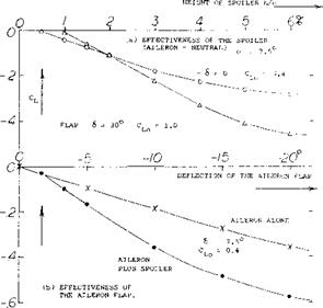
Flap Flow. An arrangement similar to the slot-lip spoiler is the plug type, mentioned before in connection with time lag and ventilation. Figure 24 presents shape and the principle characterisitcs of a configuration of this type. We see in particular:

a) that the rolling moment increases with the lift coeffi­cient, at which the spoiler is used,

b) that the effectiveness is higher with, and it grows with, the deflection angle of a slotted lift flap.

c) that effectiveness reaches a maximum at a flap angle in the order of 40°.
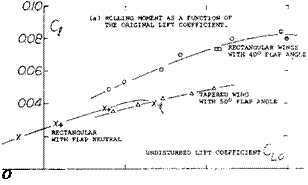
Подпись: О Подпись:The type of flap flow, whether attached or separated, is of basic importance. Any plug-type of slot-lip spoiler cannot destroy much lift produced at and due to the wing flap, unless the flow is attached to its upper or suction side. It must be concluded, accordingly, that any spoiler, when used in combination with a trailing-edge split flap (behind which the flow is always separated), will only have an

CHARACTERISTICS OF SPOILERS

2 a/b ~ 0.45 SPOILER SPAN

x/c = 0.66 SPOILER LOCATION

effectiveness somehow equal to that with the wing flap in neutral position. For illustration, see the effectiveness of the plug-type spoiler in figure 24 in presence of a wing flap deflected to 50° (where the flow must be assumed to be separated from the suction side of the flap). The high values of the lift reducing effect as in figure 21,c up to ACl = —1.7 can also partly be attributed to a reduction of the foil-section circulation because of the slot opened up ahead of the lift flap. Including flow separation from a slotted flap deflected between 20 and 40°, the slot lip as in figure 21,b has an effectiveness, measured in the form of (ACl), between —1.5 and —1.8 at undisturbed lift coefficients Cl0 between 1.1 and 2.7. Such values are roughly 2 times those of the solid-plate and some 3 times the maximum of those of the rake-type spoilers as in figure 23. Thus destroying practically all of the lift pro­duced by the foil section as well as by flap deflection, the slot-lip spoiler appears to be extremely effective at higher lift coefficients.

Induced Yawing Moments. When changing the lift coeffi­cient in the part of the wing span covered by an aileron flap or a spoiler, by a certain ACU, the induced drag for that part is calculated using equation 15 . As mentioned before (in connection with the Frise-type aileron), the significance of this differential rests in the fact that it causes a yawing moment the direction of which is op­posed to the motion of an airplane when making a turn. Since the rolling moment is the result of the lift differen­tial ACL, and the yawing moment is proportional to ACDl , we obtain the moment ratio as in equation 17. We have evaluated that equation for an aspect ratio A = 4. Experimental results plotted in figure 25 confirm the analysis well, when considering a small positive and con­stant component evidently reflecting the variation of the viscous foil section drag as a function of flap deflection.

CHARACTERISTICS OF SPOILERS

04- Qy

Ct

(a) • EQU. (9) FOR A = 4

0.6- 1 1 J

Figure 25. The variation of the yawing moment of rectangular aspect-ratio-4 wings, presented in the form of the moment ratio C„j/Cjl as a function of the lift coefficient at which lateral control is applied:

a) as indicated by theory (see text)

b) due to plain aileron deflection

c) due to a “plug” spoiler while 6=0

d) due to a spoiler in presence of a slotted wing flap deflected to 30 and 40 .

CHARACTERISTICS OF SPOILERS

Figure 26. Parasitic drag associated with the lift differential pro­duced by various suction-side spoiler devices.

Parasite Drag. When deflecting a spoiler, the flow past the suction side of the airfoil section separates. As a result of this separation there is an increase of parasite drag. Drag coefficients tested on rectangular wing models equipped with full-span suction-side spoilers are plotted in figure 26. The section drag increases in proportion to the lift differential caused by the various types of spoilers tested. Therefore:

ACds = — к (ACl ) (23)

Подпись: (21) Lift control by means of jet sheets: (a) Childress, Princeton Aero Engg Rpts 365,391,422 (1956/58). (b) Lowry, Jet Spoiler, NACA RM L53I09a. (c) Schult, Spoilers and Jet Controls, NACA RM L56H29.

where к is between 0.2 and 0.3 for forward spoiler loca­tions between 0.1 and 0.3 or 0.4 of the chord. There is one example in the graph, representing a plug-type or slot-lip spoiler, at a location x = 0.73 c. The factor к is only 0.1 in this case. The increase in parasite drag due to spoiler deflection results in an increase in the yaw to roll moment coefficients (into the more or less desirable posi­tive range) by an amount of ~ 0.2, on account of a plug-type spoiler located at x = 0.56 of the chord, figure 25. Note that the moment ratio is equivalent to the factor к in the last equation. When using spoilers in combination with slotted wing flaps (at deflection angles such as 30 or 40 where the flow is still attached to their suction side) the parasite drag due to spoiler projection is almost doubled. The factor equal to the moment ratio is between 0.3 and 0.4. In conclusion, spoilers present a usually desirable positive contribution to the yawing moment when turning an airplane. It is conceivable, however, that the positive due-to-spoiler yawing moment might be too large at smaller lift coefficients, particularly when diving an airplane at or close to CL = zero.

Combination With Aileron Flap. We have seen that spoil­ers have comparatively high effectiveness at higher lift coefficients, particularly when used in combination with a lifting (slotted) wing flap. Spoilers may also reduce the yawing caused by the rolling moment produced in the wing to zero. Combination of a spoiler with a pair of possibly small-span ailerons promises advantages as fol­lows:

Flight Testing. Wind and water tunnel investigations of the comb or rake type suction-side spoilers (as in figures 22 or 27) show among others:

a) that effectiveness is high in comparison to more down­stream locations.

b) that time lag (delay) is small, but still twice that of a conventional aileron.

CHARACTERISTICS OF SPOILERS

a) The ailerons will eliminate or sufficiently cover the time lag associated with plain spoiler operation.

b) The ailerons will also cover the dead range of their projection (such as found in figures 21,c and 27,a).

c) Ailerons will provide a desirable amount of hinge and control moment, which retractable arc-type spoilers do not have.

d) In regard to yawing moments, a suitable combination of spoiler and aileron flaps may provide the most desirable or most acceptable solution.

e) While ailerons do not function well in combination with full-span flaps, spoilers will work particularly well when placed in front of wing flaps.

An example of a lateral control system in which a short aileron is combined with a spoiler is presented in figure 28.

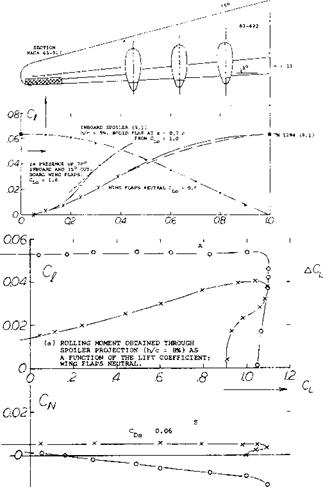
Spoiler and Plain Flap. The experimental results in figure 27 confirm the fact that (without presence of a deflected lift flap) a spoiler may not have sufficient effectiveness. Roughly, the rolling moment produced by a spoiler (pro­jected on the upper side of the foil section) is equal to that due to deflection of an aileron flap on one side of the wing. Consequently, when using a pair of aileron flaps, their combined power will be twice that of the spoiler. Using now the spoiler together with an aileron flap locat­ed behind, in the same part of the wing span, figure 27 shows that their combined effectiveness is somewhat less than the sum of their individual powers.

Spoiler Span. The model of a large 6-engine airplane was investigated as to lateral control (9m). When increasing in steps the spanwise length of a screen-type spoiler, at 0.65 chord, the rolling moment produced increases as shown in figure 28,a. For comparison, results for another series of spoilers are also plotted in the graph, beginning in the center of the wing. The function obtained is very similar to that in figure 4. Regarding yawing moments, figure 28,b shows a positive value corresponding to an increment of the section drag coefficient by ACD5 ^ 0.06. The moment due to control by means of the short-span aileron flap is, on the other hand, negative (see equations 16 and 17). Figure 28,b also illustrates the fact that a spoiler produces a rolling moment roughly equal to that of a one-side aileron flap.

A combination of rake type spoiler with a slotted wing flap and with an independent short-span aileron was sub­sequently flight-tested, in 1941, on the Ju-88 airplane. In comparison to the original condition of the airplane, the span of the ailerons was reduced to half (the wing flaps were extended, accordingly). Results are as follows:

a) At higher lift coefficients, lateral control effectiveness is higher than that of the original configuration.

b) At higher speeds (i. e. at lesser lift coefficients) control effectiveness is lower than in the original condition; effectiveness is fully satisfactory, however.

c) The spoiler’s positive yawing-moment component in­creases the control effectiveness, by avoiding yawing in the wrong direction.

d) Positive yawing moments also improve handling quali­ties in turns, when maneuvering only one of two engines, and during blind flying (on instruments).

CHARACTERISTICS OF SPOILERS

The foil, flap and spoiler configuration tested is as in figure 19. There are 30 prongs in a piece of span equal to the chord. The clear­ance between the prongs is 0.4 of their spacing, so that the spoiler solidity is 60%.

Figure 27. Effectiveness of spoiler and aileron flap as tested (17,c, d) full-span on a rectangular wing model with A = 2.6.

Jet Spoiler. Another method of spoiling the suction-side flow of an airfoil is by means of a jet discharging at a suitable location. Devices of this type are described in (21). The spoiling effect of the jet sheet is expected to be a function of the momentum coefficient

Cu = (w/v)2 (s/c) (bs/b) (24)

where w = jet velocity, s = width of the slot from which the jet issues, and b5 = spanwise length of that slot. It is said in the second of two reports (21,a), however, that “aerodynamic time lag may not be any less than for mechanical spoilers”. It is obvious that a jet sheet could as well be issued from the trailing edge of a wing thus forming a jet flap aileron, presumably with characteristics similar to those of mechanical flaps.

CHARACTERISTICS OF SPOILERS

-0.2 і

(b) YAWING MOMENTS ASSOCIATED WITH THE ROLLING MOMENTS ABOVE.

ROLLING AND YAWING MOMENTS AS A FUNCTION OF THE LIFT COEFFICIENT, CAUSED BY:

(A) PAIR OF SHORT AILERONS WITH SPAN RATIO 2 a/b = 0.13 (S) SPOILER AS ILLUSTRATED IN (a) WITH 2 a/b = 0.35.,

Figure 28. (a) Configuration tested (9,m) at Rc = 9(10)6; and rolling moment caused by spoiler projection (h/c = 8%) as a function of the span ratio 2 a/b. For comparison one-side aileron with full outboard span 2 a/b = 0.41.

(b) Rolling moment coefficient of a 6-engine pusher-type airplane model (9,m).

ROLL CONTROL OF AIRPLANES

Roll control of aircraft has been and continues to be a major design problem as it is necessary to maintain or change the attitude of the aircraft throughout the operating speed range. The control of the airplane in roll is especially important during approach and landing to provide the pilot with the ability to counter and tor hold lateral displacements in the event of gusts and engine failure. Effective lateral control during landing is also needed for proper alignment with, and touchdown on the runway. With the development of STOL aircraft the lateral control effectiveness as a function of stalling speed is an important factor in determining the landing distance, as its design directly influences the CLX of the wing. If the required CLX is not compatible with the lateral control system the only alternative is a direct reaction type of control, which can lead to considerable difficulties. The problem of providing a roll control system for STOL aircraft is compounded by the need to use full span flaps to provide peak values of CLX.

During flight maneuvers control in roll is needed in combination with yaw control and is especially important for fighter type aircraft. The need to develop high rates of roll for fighter airplanes has led to considerable research and development and consideration of many different types of systems.

DEFINITION. An aileron is a flap type device located at the wing trailing edge and capable of inducing a rolling moment through a differential deflection. The deflection angle of one aileron is defined by the angle 6 and the total angle deflection is 6^- = + 62 . Rolling

moments are also obtained by the use of spoilers of various types. The deflection of the spoiler reduces the wing lift and thus provides the necessary moment.

(1) United States Patent Office Patent No. 821,393 “Flying Machine” dated May 22, 1906.

1. CHARACTERISTICS IN ROLL.

A wing symmetrical about the longitudinal axis of an airplane, no control deflections, will maintain its attitude unless disturbed by a change in velocity or angle, for instance due to a gust. A stable type wing will tend to return to the original undisturbed position but a means of control must be provided to allow the pilot to make the necessary corrections. The original method provided by the Wright Brothers was “Wing warping” but they also referred to flaps and other means in their patent (1). Since the original invention of a means for lateral control there have been hundreds of different types of devices used and investigated for controlling the airplane in roll. Some of the more important devices developed are illustrated in figure 1. The objective of the devices used for roll control is to provide a moment, thus it is necessary to produce either an increase or a decrease of lift on opposite wing panels. The rolling moment developed is defined in coefficient form by the equation

Q =M^/qbS (1)

where “b” represents the moment arm and C| is the non-dimensional coefficient. Since the aileron changes the geometry of the wing to develop a moment it becomes like a propeller or twisted helicopter rotor. With the initial deflection of the aileron the largest moments and roll accelerations are produced. As the rate of roll is increased the moment and acceleration are reduced due to the rolling velocity until the rate stabilizes. This is known as roll damping and is measured by the damping in roll coefficient

Cip=6 C^/6 (pb/2V) (2)

where “p” is the roll rate and “V” is the free stream velocity. The rate of roll achieved by a given system depends on the aileron effectiveness, the wing initial operating lift coefficient, the planform and its flexibility.

ROLL CONTROL OF AIRPLANESПодпись: FRISE AILERON UNSHIELDED HORN BALANCE

ROLL CONTROL OF AIRPLANES

BALANCED AILERON

ROLL CONTROL OF AIRPLANES

SEALED INTERNAL BALANCE

DEPRESSED FABRIC FUDGED FABRIC

ORIGINAL CONTOUR

ROLL CONTROL OF AIRPLANES

BEVELED TRAILING EDGE

SURFACE COVERING DISTORTION

ROLL CONTROL OF AIRPLANES

SPRING TAB

RETRACTABLE ARC SPOILER

ROLL CONTROL OF AIRPLANES

SLOT LIP AILERON PLUG AILERON

SEE ALSO FIGURES 8, 21, and 22.

Figure 1. Various types of lateral control devices.

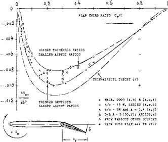
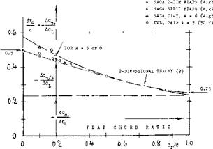
The aileron effectiveness ratio is measured by doc /d6 which as noted in Chapter ЇХ corresponds to the lift change due to the flap deflection compared t:> the lift change due to a change in section angle of attack. This measure is a function of the flap chord ratio and thickness ratio of the flapped section, figure 2, Chapter IX,

An aileron to be effective must of course operate on the wing section below the stall angle. Thus as a result of an aileron deflection lift will continue to increase. This is an important consideration, especially in the design of lateral control devices for vehicles which must land at low speeds such as STOL and general aviation aircraft.

The deflection of an aileron can result in high twisting moments in the wing structure which reduces the moment generated. As the speed is increased this adverse twist increases until the loads become high enough to cause a reversal where the airplane will roll in the opposite direction to the control deflection produced at low speed. This speed is known as the aileron “reversal speed ”.

(2) Lateral Control Specification:

(a) Perkins, Airplane Performance Stability & Control, J Wiley & Sons, Inc., 1949.

(b) Toll et all, Summary of Lateral-Control Research, NACA TR 868.

(c) Gillruth Control Requirements, NACA TR 755.

(d) Stability and Control Requirements, AAF Spec. No. R-1815.

(e) Creer, B. Y. and all Lateral Control Requirements, NASA Memo 1-29-59A.

Design Requirements. Many specifications have been published relating to the design requirements for roll control and the associated lateral control devices (2). The older specifications for lateral control generally related the requirement to the parameter pb/2V the helix angle described by the wing tip (see later section Helix Angle). For large cargo and bombardment type aircraft the minimum value of pb/2V was considered to be.07 for full aileron deflection and.09 for fighter types. The use of the parameter pb/2V is somewhat arbitrary for specifying lateral control devices and, therefore, better means have been developed. For instance, some specifications require the achievement of a certain bank angle after one second where other specifications require that the airplane be capable of making a 20° banked turn with or against a failed engine. It appears, however, that a better specification would include the effects of roll damping and aileron control power in terms of roll acceleration (2,e). Since lateral control specifications change periodically the current requirement must be established for design use.

In addition to providing the required roll effectiveness the lateral control system should also provide a linear roll response to a control motion without adverse coupling into yaw or pitch. Generally the yaw coupling is the most important and it is desired to develop the roll without retarding the forward movement of the up going wing. Spoilers have a favorable yaw characteristic in this sense.

Flap Type Ailerons. Conventional ailerons are basically “flaps”. However, their characteristics differ from those of elevators and rudders, as follows:

a) They are practically always part-span

b) The control forces are a combination between left and right

c) Their lift coefficient, on the average, are higher than that of tail surfaces

d) yawing (side-slipping) effects the characteristics of ailerons.

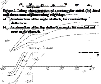
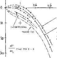
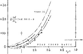
Figure 2 shows lifting characteristics of three sizes of plain flaps which could be used as ailerons as tested on an airfoil having an aspect ratio of 6. For example, as shown on figure 2,a, at a positive angle of deflection of 10°, the lift is shifted to higher levels, the level depending on the flap-chord ratio. Within the range of moderate flap deflec­tion angles, the lift coefficient varies along straight lines, the slope being a function of the chord ratio corre­sponding to principles explained in connection with figure 2, Chapter IX. As in other control flaps, separation takes place (a) from the flap, above a limiting deflection be­tween 15 and 20° ; (b) from the suction side of the airfoil and flap, as a function of the angle of attack (at lift coefficients roughly above 1.0). As with landing flaps, the maximum lift coefficient is increased corresponding to flap chord and angle of deflection. In separated condition,

the lift still increases (at a lesser rate) as a function of the angle of deflection, particularly as long as the flow is still attached to the forward part of the wing section. At a1 = constant = 0, the coefficient reaches a maximum in the vicinity of 6 = 70°, figure 2,b. As in tail surfaces, theoretical analysis is restricted to the linear portions of the lift forces (and the associated moments). The sta­tistical results, for example as in figures 2, 7, 8 of

Chapter IX, readily apply to wing sections using plain aileron flaps.

ROLL CONTROL OF AIRPLANES

Part-Span Flaps. Since ailerons practically never extend over all of the full wing span, the characteristics of part – span flaps are of interest. Experimental evidence is meager in this respect. Results of one investigation are illustrated, however, in figure 3, where the lift-curve slopes of the wing due to flap deflection is given as a function of the flap-span ratio for the cases

a) when increasing the flap span from the center line (case of a pair of wing landing flaps)

b) for a pair of outboard flaps, representing ailerons.

ROLL CONTROL OF AIRPLANES

The lift produced increases with the span ratio as indi­cated on figure 3 and inboard flaps are more effective (as to lift, not as to rolling moment) than outboard flaps. Estimated slopes of the lift coefficient based upon the wing portions “covered” by the flaps, are also plotted in figure 3. The slope is highest in the wider vicinity of the wing center, and it drops off around the wing tips.

The lift-curve slope of the wing portions “covered” by ailerons, due to their angle of deflection, corresponds to the da /dcf ratio as in figure 2, Chapter IX. The dCL /doc to be used, is not that of the wing, however, (a) because the ailerons occupy only part of the wing span,

(b) because the deflection of conventional ailerons is antisymmetric (up on one side, and down at the other). Theory predicts that for the lift differentials plus and minus ACl of a pair of full-span ailerons, the effective aspect ratio is half of that of the wing.. If, for example, A = 6 the flap angle required to produce a certain lift differential must be based upon the induced angle of attack

da; /dCL = l/(rr 0.5 A) =

“ 57.3/(тґ3) ~ 6° (3)

where 57.3 = 180/гґ. Each wing panel’s effective :.ft angle (Chapter III) is then

da/dCL —10 + 6= 16°,
instead of 10 + 3 = 13°

and the effective lift-curve slope for ACL is 1/16° = 0.062 instead of 0.077 as for the wing as a whole. Con­ventional ailerons are only part-span, however. Con­sidering, for example, an aileron flap adjoining the lateral edge of a rectangular wing, with the extremely small span ratio a/b = 0.1 only, we may expect the effective aspect ratio (as far as lift due to aileron deflection is concerned) to be between 1.0 (geometrical) and 2.0 (when assuming that the rest of the wing acts as an end- or reflection plate).

Assuming that equation (3) may still hold for aileron-span ratios in the vicinity of 0.5, the lift differential produced by a pair of antisymmetrically deflected ailerons of a given chord ratio is

Л CL » (dCL /doc (Sa /S)(doC /doc )rf (4)

where “2” indicates that the lift-curve slope corresponds to 1/2 the actual aspect ratio, or to 2 times the wing’s induced angle of attack. In the case of rectangular wings, the ratio of the effective area covered by one of the two ailerons, is:

SQ/S = a/b (5)

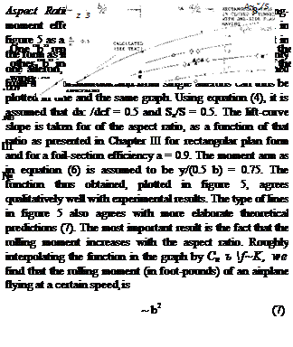
where “a” = spanwise length of one aileron flap. The moment arm “y” of the lift differentials (about the center line of wing or airplane) may be assumed to be that of the geometric center of Sa. The rolling-moment coefficient Cj = M^/qSb, of a pair of ailerons corresponding to a given area and chord ratio is then:

dC^ /d(A cf ) = A CL y/0.5 b (6)

where A cf = deflection-angle differential between one side and the other. In aileron systems where up and down deflections are equal, the differential is Д cf = 2/cfA

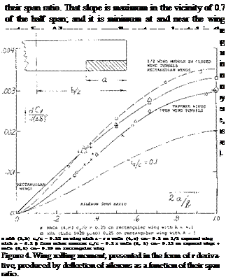
Part-Span Ailerons. Rolling moments due to aileron de­flection are plotted in figure 4 against the span ratio. The slope of the lines in the graph is a measure for the rolling-moment effectiveness of ailerons as a function of

ROLL CONTROL OF AIRPLANES

Rolling Moment Due to Aileron Deflection. When ini­tiating or reversing a roll, motion is caused by a rolling moment. This moment can easily be measured statically using wind tunnel models of wings or airplanes. The angle of attack in the wing panels is uniform and cor stant in this case. The rolling moment “Mj” (5) is the conse­quence of lift differentials produced by antisymmetric aileron deflection. Theoretical methods are available (6) for predicting rolling moments due to aileron deflection. Considering a part-span aileron, the initial moment pro­duced corresponds to:

a) the wing area “covered” by the aileron

b) the chord ratio of the aileron flap

c) the deflection angle of the aileron

d) the moment arm (aileron to center line)

e) the wing twist due to aileron loads.

(4) Ailerons and lateral airplane control:

(a) Toll, Summary, NACA T Rpt 868 (1947).

(b) Weick, Airplane Motions, NACA T Rpt 570 (1936).

(c) Weick, Lateral Control Research, NACA T Rpt 605 (1937).

(d) Weick, Ordinary Ailerons, NACA TN 449 (1933).

(e) Weick, Skewed Ailerons, NACA T Rpts 444 & 445 (1932).

(f) Weick, On Wing with Slat, NACA TN 451 (1933).

(g) Heald, Chord and Span of Ailerons, NACA T Rpt 343 (1930).

(h) Gilruth, Lateral Control Required, NACA T Rpt 715 (1941).

(i) Weick and Wenzinger, Ordinary Ailerons, NACA T Rpt 419 (1932).

(j) Johnson, Various Ailerons, NACA TN 2199 (1950).

(k) Naeseth, Influence of Aspect Ratio, NACA TN 2348 (1951).

(l) Fischel, At High Speed, NACA TN 1473 (1947).

(m) Fischel, Aspect Ratio, NATA T Rpt 1091 (1952).

(n) Higgins, Flap and Aileron, NACA T Rpt 260 (1927).

(o) Schneiter, Span and ТЕ Angle, NACA TN 1738 (1948).

(5) The indicates the longitudinal axis about which the

motion takes place.

(A)

ROLL CONTROL OF AIRPLANES ROLL CONTROL OF AIRPLANES

rectangular wings:

* NACA (4,m) with cf/c = 0.25 ■ NACA (6,k) with cf/c = 0.15

(B) tapered wings:

4 NACA (6, k) with с /с «0.20 x NACA (6,k) with c|/c **0.15 Q other sources with Cf/c – 0.20 and = 0.25

(C) wings with round tips

О NACA (6,k) with cf/c 0.20

Figure 5. The rolling-moment derivative of approximately half­span ailerons as a function of wing aspect ratio.

(A) rectangular wings

(B) tapered wings

(C) wings with round tips.

Tunnel Testing. Conditions of antisymmetrical aileron de­flection are not always simulated in wind-tunnel tests. This is particularly true when half-span models are used

(3) in closed test sections (8). Differentials as indicated in figure 5 are due to:

a) tapered as against rectangular wing shape cf/с = 0.20 as against = 0.25 and wind-tunnel interference

b) wings in open as against closed-type wind tunnels full — as against half-span wing models

c) “round” wing as against rectangular c. P/c ‘•= 0.15 as against = 0.25

In conclusion, rolling moments available for tapered wings under realistic conditions are less than those obtained when testing wind tunnel models with rectangular wings.

Aileron Effectiveness. The static rolling moment produced by aileron deflection may be approximated as being pro­portional to (/A(2a/b)vc77c). For aircraft where the hinge moment is a limiting factor Cw and thus :he hinge moment per degree of aileron deflection is a design condi­tion. Evaluation of the data plotted in figures 4 and 5 leads to

dCb,/d(A& ) ^ k(/A(2a/b)/c^T"c) (8)

where after elimination of closed-tunnel and half-wing model results, the factor is

к ^ 0.0035 for “round” wings

^ 0.0040 for tapered wings

^ 0.0045 for rectangular wings

“Round” means shapes which are rounded off at the wing tips, thus cutting away from the outer end of the aileron flaps.

Rolling Velocity. The static rolling moment produced by aileron deflection, discussed so far, can only be present at the beginning of a roll. The moment is, therefore, a measure for the rotational acceleration of an airplane when going into a rolling motion as previously noted. Another measure for aileron effectiveness is the lerminal rolling velocity obtained in a steady roll. This rotational speed is usually given in the non-dimensional form of the speed ratio

u/V = pb/2V (9)

where the circumferential speed of the wing tips u = p(0.5b)

and p = angular velocity about the longitudinal airplane axis (in radians per second).

Helix Angle. Note that u/V is the angle against the normal plane of the helix line along which the wing tips move during the motion. Typical maximum helix angles of World War II fighter airplanes as listed in (4,a) are

u/V = pb/2V = between 0.06 and 0.12 (10)

measured in radians. The values obtainable at higher speeds (where stick forces are the limiting element, are only half of those stated. The rolling velocity of these airplanes are roughly between 50 and 130 degrees per second. As a function of their size it can be said that there is a tendency toward constant up or down wing-tip speed u. For example, at a lift coefficient of ~ 0.8 (after take-off or when approaching the landing field) a fighter with a span of 35 ft and an airliner with 120 ft, might both be able to move their wing tips, up or down, at a maximum speed in the order of 20 ft/sec.

Rolling Effectiveness. The effectiveness of a lateral con­trol can be described by the ratio of the wing helix angle pb/2V to the aileron deflection angle. The helix angle described by the wing tip is uu, eq (9). Using constant units, radians or degrees we obtain the non-dimensional derivatives

dixj/db = l80d(u/V)/Tr6o (11)

In terms of the wing damping ratio eq (11) becomes

du>/d6 =dQ/Cipd6 (12)

Thus the effectiveness in roll is measured by the ratio of the rolling moment per degree to roll damping. This effectiveness parameter is a function of size of the aileron as well as the aspect ratio of the wing, and for practical purposes is

dw/d6~ (2a/b)cp /c//A~~ (13)

(7) Unconventional types of ailerons:

(a) Weick, Floating-Tip Ailerons, NACA T Rpt 424 (1932).

(b) Weick, Floating-Tip Ailerons, NACA TN 458 (1933).

(c) Weick, Short-Wide Ailerons, NACA T Rpt 494 (1934).

(d) Sawyer, On ТЕ of Wing flap, NACA T Rpt 883 (1947).

(e) Ashkenas, With Large-Span Flaps, NACA TN 1015 (1946).

(f) Dearborn, Zap Ailerons, NACA TN 596 (1937).

(g) Reed, External-Airfoil Flaps, NACA TN 604 (1937).

(h) Weick, External Ailerons, NACA T Rpt 510 (1935).

(i) Soule, Flight Tests Full-Span Flaps, NACA T Rpt 517.

(j) Platt, External Airfoil Flaps, NACA T Rpt 603 (1937).

(k) Fishel, Collection of Data, NACA TN 1404 (1948).

(8) The aileron angle should be corrected in the same direction as the angle of attack, with dof/d6 applied as factor of propor­tionality.

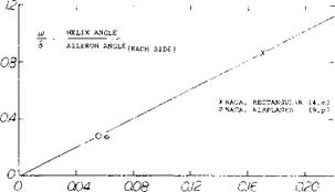
A wing with a large aileron and a small aspect ratio would therefore have a higher rolling effectiveness per degree deflection than the same aileron on a long wing. From the statistical values derived from test data, figure 6, we see that for example at (2a/b)cf/c/A equal to 0.1 that w/6 equals.5. Thus, the rolling velocity of an airplane can be calculated as a function of the aileron dimensions used and the aspect ratio. For the case of two ailerons deflec­ted a total increment of 6 , the equation for rolling effectiveness is from figure 6 approximately

*/6 = 2.5(2a/b) /ср /с/ Уа~= u/V 6 (14)

so that the wing tip speed ratio is

u/V – ISO 8° (tu/6 )

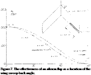
Sweepback. It is explained in Chapter IX how control flap characteristics change with the angle of sweep. As a conse­quence, aileron effectiveness reduces basically in propor­tion to cosM, when keeping the aspect ratio constant. Experimental results from a series of swept wings are plotted in figure 7, showing good agreement with the theoretical prediction even though the aspect ratio is not kept constant in this investigation.

Internal Force. In contrast to elevators or rudders, flap type ailerons are always provided in pairs. They moye antisymmetrically against each other and they are inter­connected by means of a linkage system. In neutral posi­tion the hinge moments of the aileron flaps are usually somewhat “up”, on account of positive wing lift. The structural element (rod or possibly cable) connecting the two sides, therefore, takes up the corresponding “intern­al” force, for example in the form of tension.

ROLL CONTROL OF AIRPLANES

ROLL CONTROL OF AIRPLANES

Подпись:

AILERON PARAMETER ( VcJ7c (I a/h)/VK)

Figure 6. Helix-angle derivative of airplane wings; statistical evalua­tion of wind-tunnel and flight tests as a function of a parameter indicating the aileron size. [95]

Stick Force. The control moment (stick force) is the sum of or the difference between (depending on the sign definition) the right and the left aileron. Primarily, there­fore, the lateral stick force corresponds to the flap hinge moment derivative dCH /d6 . In fact, in a steady roll (with deflection, rate of roll and lift coefficient ~ con­stant) the hinge moments of plain ailerons can correctly be determined on the basis of figure 8, Chapter IX. On the other hand, stick forces for sudden aileron deflection (when initiating or reversing a roll) correspond to the total derivative as in equation (24) of Chapter IX, where CL represents the plus-minus ACL produced by the ailerons.

Differential Linkage. The wing’s lift and the flap hinge moment corresponding to that lift can be utilized to reduce lateral stick forces, when desirable. As mentioned above, each aileron flap usually has an up-floating tenden­cy. By designing the linkage system connecting the two ailerons with the control stick (or wheel) in such a manner that the up-going flap has a somewhat larger deflection than of the corresponding down-going flap, it is realized that the mean deflection of the two flaps of 0.5(<f, +

cf2 ) is somewhat up. The lift or normal force supported on the surface of the pair of flaps operating at opposite angles, ailerons, helps reduce the hinge moments produced by their deflection. For practical results see (10).

ROLL CONTROL OF AIRPLANES

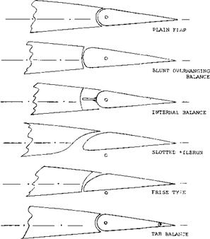
Figure 8. Various flap shapes and types of balance suitable to be used as ailerons.

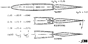
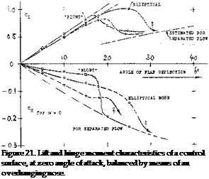
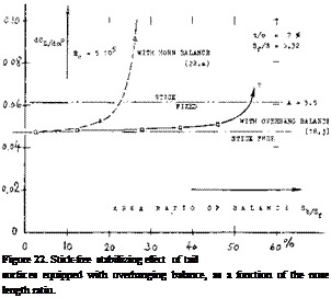
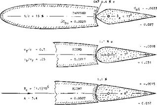
Nose Balance. To reduce the hinge moments of aileron flaps some type of overhanging nose can be used as described in Chapter IX and shown on figure 26. In fact, symmetrical (and comparatively blunt) open noses have occasionally been used. The external-horn balance was at one time found to be convenient and sufficient to balance the ailerons of smaller and low-speed aircraft, such as certain Fokker airplanes. Another possibility of balancing aileron flaps is the internal type, see figure 8. [96] [97]

ROLL CONTROL OF AIRPLANES

Figure 9. Slotted aileron flap tested (11 ,k) on rectangular airfoil with A = 2.4 in open wind tunnel.

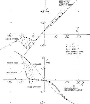
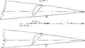
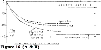
Slotted Ailerons. Because of the “always” positive lift of the wing to which ailerons are attached, flap-section shapes favoring suction-side flow are desirable. One such type is the slotted aileron, evidently fashioned after (or developed during the same period of time as) the slotted type of landing flap described in Chapter V. Figure 9 shows that such ailerons have unsymmetrical hinge- moment characteristics. The flap nose is comparatively inefficient at positive angles of deflection, while in the range of negative deflection suction forces of appreciable magnitude develop past the lower side of the nose as it emerges from the contour of the foil section. When com­bining hinge moments of one side up with the other side down, fairly straight control (stick) moments can be ob­tained, however, as illustrated later. Figure 10 presents hinge-moment derivatives for positive and negative deflec­tion.

(11) Investigation of slotted and Frise-type aileron flaps:

(a) Weick, Slotted Ailerons, NACA T Rpt 422 (1932).

(b) Hartshorn, Frise-Type, ARC RM 1587 (1934).

(c) Kaul, Slot Shape, Yearbk D. Lufo 1941 p.1-315.

(d) Ehrhardt, Me-109 Ailerons, Messerschmitt WKB 2 (1943).

(e) Purser, Analysis of Data, NACA W Rpt L-665 (1944).

(f) Batson, Surface Curvature, ARC RM 2506 (1953).

(g) Aileron Flap Camber, ARC RM 2495 (1947).

(h) Letko, Frise-Type Aileron, NACA W Rpt L-325 (1943).

(i) Hoerner, Ju-228 Aileron Tested on Full-Scale Wing, Junk­er Rpt Kobu-Ew 895 (1941).

(j) Toll, Hinge Moment Parameters, NACA TN 1711 (1948).

(k) Junkers Wind-Tunnel Results Strote Graphs D-6761 (1941).

Yawing Moment When turning an airplane, both the ailerons and the rudder are deflected in proper direction. Most or all of the rudder displacement is required, how­ever, not to make the turn, but simply to compensate for the adverse or “negative” yawing moment produced in the wing panels by deflection of conventional ailerons. Ailer­on flaps change lift; lift is increased in one* side and decreased in the other side of the wing. With the change in lift, induced drag (equal to local lift times induced angle) is increased in the outside wing panel, and it is decreased in the other panel. Considering a pair of symmetrically deflected ailerons, the induced-drag differential in each wing panel corresponds to

ACdl = ACl (o^O =

(ACl )2Clo /(1ҐA) (15)

where the function for (otL ) is in equation (3). Since ACl is positive on one side of the wing and negative in the other, a yawing moment is thus obtained correspond­ing to 2(ACdl )y, where у = moment arm to wing center line. The coefficient of the moment (11) of a pair of ailerons is then:

Cn = Mn/(q S b) =

4(У/Ь)(ДСи ) CLO / (VA) (16)

where Д CL is in equation (4). The ratio of yawing to rolling moment is

Cn/C* =-ACdL/ACl =

-4Clo /(‘TfA) = – 1.28 CLO /А (17) [98]

ROLL CONTROL OF AIRPLANES

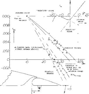
Figure 10. Statistical evaluation of the hinge moments of slotted aileron flaps.

where the minus sign signifies that the yawing moment is adverse to the turning maneuver of the airplane. Such yawing moments coupled with roll control complicate handling of the airplane. “Negative” moments also reduce the magnitude of the rolling-moment and the resultant rate of roll, unless the pilot fully compensates by means of the rudder.

The “Frise” Aileron. This type aileron, figure 8, was invented (11) to reduce or to compensate for the unfavor­able “negative” yawing moments associated with flap-type lateral control devices. It was expected that flow separa­tion would soon take place after the sharp lower edge of the aileron nose moved out into the flow. Parasitic drag corresponding to such separation was to counteract the undesirable variation of the induced drag as described above. The disadvantages of this design are:

a) flow separation is bound to reduce effectiveness.

b) separation is likely to be accompanied by fluctuations and vibrations.

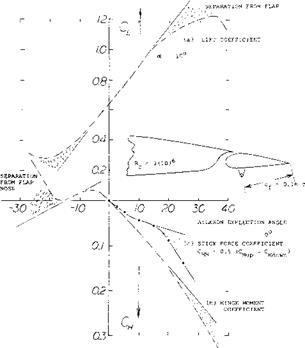
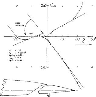
Figure 11 shows shape and characteristics of a typical Frise-type aileron flap. When deflecting this flap down­ward, lift increases steadily, and it continues to do so in the presence of flow separation developing along the suc­tion side of the flap. This separation is evident from, and/or it results in a progressively increasing hinge mo­ment. When deflecting the flap upward, strong suction forces develop at first around its lower leading edge as it emerges from the foil-section contour. Depending upon the sharpness of the edge, separation along the lower side’ of the flap starts at negative deflection angles between 7 and 15 . As a consequence, effectiveness reduces consid­erably while the hinge moment increases rapidly, from approximately zero to a level as indicated by a line con­necting the two extremes of the hinge-moment function, figure 11.

Stick-Force Coefficient. Average derivates as found, re­spectively, in the positive and negative branches of the hinge-moment function of slotted and/or Frise-type ailer­on flaps, are plotted in figure 10. When adding the values of the hinge-moment contribution from one side (down, for example) to that of the other side (up) we obtain a number representing the lateral stick force required to deflect a pair of ailerons. Dividing the combined value by 2, we obtain the stick force coefficient, properly referred to the sum of the aileron areas:

СЦу =: 0.5(CUup —Cydoujn) (18)

ROLL CONTROL OF AIRPLANES

ROLL CONTROL OF AIRPLANES

NOTE: OSCILLATIONS WERE OBSERVED AT THE NEGATIVE ANGLE

OF STALL, WHERE CH INCREASES AND CL CHAISES SLOPE,

Figure 11. Characteristics of a Frise-type aileron flap tested in a two-dimensional wind-tunnel set-up (11,h), for two different lead­ing-edge radii.

f

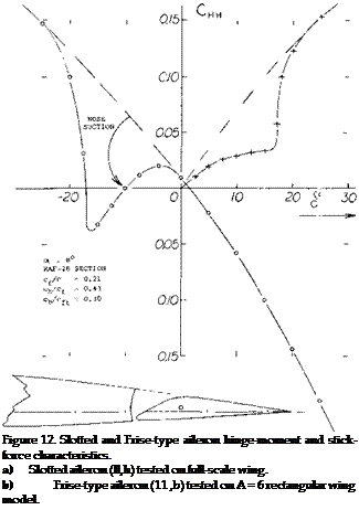
Examples for the stick-force characteristics of two aileron flaps are presented in figure 12. Practical results are as follows:

a) Comparatively irregular CM (cf ) functions of the single aileron can result in a surprisingly smooth stick-force variation. Truly, one side compensates for the other.

b) In case of the Frise-type aileron, the more or less sudden separation from the lower side of the flap nose produces a more or less steep increase of the stick – force coefficient.

c) A reduction of the hinge moments to half, to a third or possibly to a quarter seems to be feasible or to be the practical limit for this type of overhanging-nose balance.

d) Note that the effectiveness of the Frise-type aileron flap discontinues as separation from the nose takes place.

Stick-Force Slope. Considering the Frise-type aileron as in figure 11, it can be realized that when putting together the right-or-up with the left-or-down flap, the resultant stick force has a slope around the neutral position at 6 = 0, practically equal to zero. A control system with such a characterisitc is not desirable. To increase the stick-force slope, the flap deflection at which the slope of the hinge moment is zero, should be somewhat negative (such as in figure 9 and 12, for example). Means of shifting that angle are as follows:

a) Adjusting the neutral position of the two aileron flaps to a somewhat positive angle.

b) Displacing the flap nose sufficiently up so that it emerges from the foil-section contour at a somewhat more negative angle of deflection.

c) Combination of (a) with the use of a trailing-edge tab, compensating for the change of lift coefficient and pitching moment (Cmo) resulting from (a).

Taking into consideration that the hinge-moment and stick-force characteristics are also a function of angle of attack or lift coefficient, it will be appreciated that the type of overhang-balanced ailerons described above can be very cumbersome when attempting to reduce the hinge moment substantially.

Rigging-Up. The slotted type as well as the Frise form of ailerons are characterized by hinge moments:

a) increasing strongly within the range of positive flap deflection

b) roughly equal to zero (or somewhat unstable) for upward deflection.

As a consequence, the resultant control-stick moment essentially corresponds to the positive hinge-moment slope of down-going aileron flap. As mentioned above (under a), the relative contribution of the two sides can be changed, however, by changing the neutral position of the flaps. Pulling down both ailerons will thus increase the stick force required, while rigging up as described in (13,a, b) may appreciably reduce that force. Here again, the use of tabs (as mentioned in c above) may be desira­ble.

(13) Rigged-up aileron characteristics:

(a) Weick, Rigged-Up Ailerons, NACA T Rpt 423 (1932).

(b) Murray, Rigged-Up Ailerons, NACA W Rpt L-289 (1944).

ROLL CONTROL OF AIRPLANESПодпись: Figure 12. Slotted and Frise-type aileron hinge-moment and stick- force characteristics. a) Slotted aileron (ll,h) tested on full-scale wing. b) Frise-type aileron (11 ,b) tested on A = 6 rectangular wing model. Tab Balancing. The various types of tabs described in Chapter IX can be and have been applied to ailerons. The linked or geared tab is particularly effective in reducing hinge moments and lateral stick forces to a fraction of what they are for plain aileron flaps. However, due to the reduction of the stick-free lift-curve slope in linked-tab configurations, possibly to zero for higher flap-chord – ratios, such arrangements may not be permissible in larger airplanes. Thus for the case of a rolling motion, the ends of the wing covered by aileron flaps may be deficient in damping qualities, caused by a reduced lift curve slope for the case of the stick or control wheel free. As a conse­quence, the airplane would continue to roll once this motion has started, and the airplane would not be stable about its longitudinal axis for the “stick-free” case.
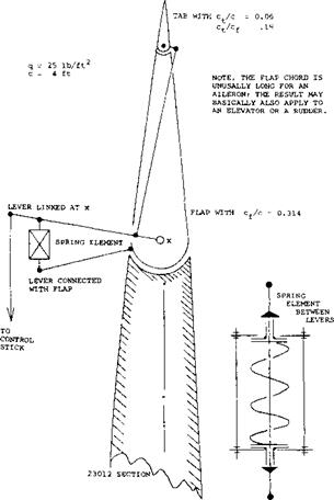
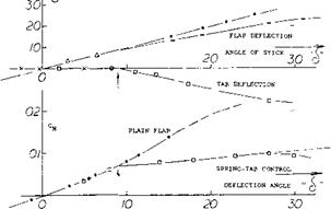
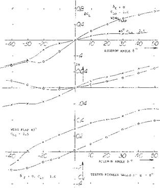
Spring-Tab Ailerons. Stability can be restored or main­tained by restricting tab operation in such a manner that for zero hinge moment (corresponding to stick-free con­dition) and a suitable range of lower hinge moments, operation is just as that of an unbalanced plain pair of aileron flaps. This is done by means of the arrangement as in figure 13 where there are two levers “leading into” each aileron flap. One of these driving the tab is directly connected with the control stick, while the other one, rigidly attached to the flap, is linked to the main lever by means of a spring element. This element as shown in figure 13 has the following characteristics:

a) As long as the flap’s hinge moment is small, the element acts as a rigid link. This is obtained by pre – loading the spring. Control characteristics are then those of a plain flap.

b) When the flap hinge moment is large, the spring com­presses corresponding to its mechanical constant. As a consequence, any lateral displacement of the control stick directly deflects the tab, which provides the moment necessary to drive the aileron flap in the opposite direction. This system thus behaves like a servo-tab type control.

c) Under conditions between the two extremes under (a) and (b) the torque deflecting the aileron flap is the sum of that due to tab deflection plus that corre­sponding to the force transmitted through the spring.

Effectiveness. The flap or control angle at which the spring starts to be compressed and the tab to be deflected depends upon the preload provided and the dynamic pressure at which the system is tested or used. In the case as in figure 13, the “critical” angle happens to be 6 = 9° . Above this angle, the tab deflects corresponding to d(dt. )/d“cf ” ~ -0.8, while the loss of flap deflection due to spring compression is d(A<f )/d“cf ’ “0.3. The

resultant loss of effectiveness is

Д (dCL /d6 ) =

(dCL /d6 ) ((d(A 6 )/d“6 ”) + (db /dSt }

(d6t /d“6 ”)) (19)

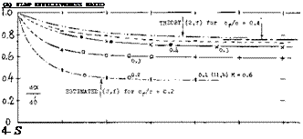
where (dCL /d5 ) = 0.033 as tested and (d& /d<St ) = (dot /d6t )/(dot /d5 ) = 0.2/0.6 = 1/3, as found in figure 2, Chapter IX. The numerical result is

(dCL/d& ) =

-0.033 (0.3 + (1/3) 0.8) = -0.019

As a consequence, the lift continues increasing above 6 = 9° at the rate of dCL /d6 = 0.033 -0.019 = 0.014. The reduction of effectiveness is appreciable in the case considered, where, Cp/c = 0.31.

Control Moment. The hinge moment of the plain aileron flap investigated, corresponds to CH<5 ^ 0.008. Disregarding the loss of flap deflection as stated above, the balancing moment provided by the tab can be expected to be as indicated in figure 36, Chapter IX where we tentatively find dCM Id6±° = —0.01. Consequently:

A(dCw /db ) = (dCM/d6t )(d6t /db )==

-0.01 (0.8) = -0.008

which is sufficiently close to the differential as tested between cT =10 and 20 . The average reduction at higher flap angles is roughly 50% under the conditions as tested. Upon reducing the spring’s preload, reduction of the control moment down to 25% could easily be obtained, while still retaining a range of no tab deflection in the order of plus and minus 5°.

Full-Span Wing Flaps. All modern airplanes are equipped with wing flaps in order to reduce landing and, to a lesser degree, take-off speed. Such flaps are, of course, most effective when extended over the entire span of the wing. Lateral (roll) control by means of ordinary ailerons, is then complicated by reasons as follows:

a) the ailerons interfere with the outboard part of the wing flaps, so that the rolling-moment coefficients obtained are somehow reduced.

b) the rolling moments in feet-pounds, being proportional to 1/CL, are appreciably reduced when increasing CL by means of wing flaps.

c) Подпись: Юг 0.8- 0.6- 04- 0.2- Подпись:ROLL CONTROL OF AIRPLANESПодпись: PLAIN FLAPПодпись: I CRITICAL ANGLE = f(PRELOAD)Подпись: SPRING-TAB OPERATIONROLL CONTROL OF AIRPLANESПодпись:Подпись: о 40r Подпись:Подпись: 20Подпись: ЗОПодпись:Подпись:Подпись: (c) HINGE MOMENT AT CONTROL LEVERROLL CONTROL OF AIRPLANESthe adverse yawing moments connected with Пар-type ailerons grow with the lift coefficient, while those obtainable from rudder deflection (needed to balance the aileron-induced moments) reduce as 1/CL.
ROLL CONTROL OF AIRPLANES

Figure 13. Example for spring-tab configuration on a 23012 airfoil section tested (14,b) between tunnel walls but with “aileron” flap only covering one half of the span.

The last complication can indeed come to the point where adverse yawing and side-slipping produce an adverse rolling moment large enough to move the airplane against the ailerons. To overcome the difficulties listed, improved and/or new types of lateral control devices have been developed. There are basically two types of such devices:

a) trailing-edge flaps similar to, or modifications of, ordinary ailerons

b) several types of spoiling devices at the upper wing side.

Trailing-Edge Deflection. An obvious method of roll control in flapped wings is by means of certain outboard portions of the wing (lift) flaps themselves. Figure 2 demonstrates, however, that not much effectiveness may be expected beyond a flap deflection in the order of 20°. The only means of improving the effectiveness is, in this case, differentiation of the aileron motion in such a manner that the upward displacement is larger than downward. In the end all that this control system amounts to is a pair of ordinary or possibly slotted ailerons, pulled down somewhat (say by 20°) together with some type of inboard wing flaps. All of the disadvantages listed above apply to the system.

ROLL CONTROL OF AIRPLANES

ROLL CONTROL OF AIRPLANES

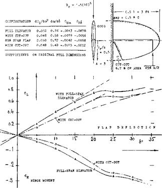
Figure 14. Combination of a plain trailing-edge aileron flap with a slotted lift flap, tested (7,k) between tunnel walls.

Duplex Flap. Figure 14 shows characteristics of a plain aileron flap attached to or located at the trailing edge of a slotted lift flap. Results of the two-dimensional investigation are:

a) The aileron effectiveness at 40° lift-flap deflection is but ~ 30% of that at zero deflection.

b) Effectiveness at negative aileron angles is generally slowly increasing, while that at positive angles is de­creasing.

c) The wing-flap position has little influence on the varia­tion of the hinge moments CH<? .

d) Because of (dCw/dod) the aileron is loaded in its neutral position.

On the basis of (b) aileron linkage could be arranged in such a manner that upward deflection is larger than down­ward. The “up-floating” hinge moment as under (d) would then reduce stick forces, but it would at the same time reduce the stability of the roll-control system. In conclusion, aileron effectiveness is not provided by duplex flaps where it is needed most, namely at higher lift coeffi­cients (and at associated lower flying speeds).

Split-Flap Aileron. Split flaps are ordinarily not used for control purposes. Their lift-producing characteristics are similar to, if less effective than, those of conventional control flaps. Figure 15 shows the combination of two such flaps. Although both flaps could be deflected in the same direction as ailerons, only the upper one was used for control purposes during wind-tunnel tests. Results of the investigation are as follows:

a) Aileron effectiveness for a split-flap deflection of 60° is slightly higher than for neutral position.

b) Hinge moments for 60° lift-flap deflection correspond to the effectiveness as in (a).

c) Both effectivness and hinge moment have a tendency, near the neutral position of the aileron flap, of lagging. It appears that the flap has to penetrate “through” the boundary layer before it can become effective.

d) The “viscous” or parasitic component of drag in­creases as a function of the aileron deflection angle. This increase (connected with the upward, lift – reducing deflection of the flap) is very desirable in turning maneuvers of airplanes.

Regarding (d) it should be noted that the differential of the section drag coefficient is positive for negative (up) deflection of the aileron flap, while that in figure 14 is negative. In conclusion, it may be said that among the flap-type ailerons tested the split-flap type appears to be the most effective design to be used in combination with full-span wing flaps. In regard to high-speed drag (when the wing flaps are in neutral position) it seems to be necessary to deflect an outboard position of the lift flap together with the upper-side aileron flap for roll control.

COMPRESSIBILITY EFFECTS ON CONTROL SURFACES

As discussed in Chapter VII the effect of compressibility in the subsonic range is to cause an increase of the slope of the lift curve below the critical Mach number and a sharp change in both lift and drag above the critical Mach number. Since it is desirable to have no sudden changes in the control characterisitcs of the airplane with changes of speed, compressibility effects are important consider­ations in the design of control surfaces.

COMPRESSIBILITY EFFECTS ON CONTROL SURFACES

MACH HO. M

Q L.. -1____ 1——- 1——- 1——- і——— 1—– 1

; .3 4 -5 .6 7 .8 .9

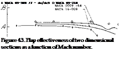
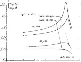
Flap Effectiveness Ratio. As shown on page 9-2, effectiveness ratio of flaps is determined by the ratio of dCL/d6 to dCL/do( or d<Y/d6. For a flapped airfoil two dimensional operating below the critical Mach number tests (51,a) show that both lift curve slopes will increase with the Prandtl-Glauert factor 1//1- Мг. The effective­ness ratio then should not change below the critical Mach number at least for flaps mounted on a two dimensional airfoil. This is illustrated on figure 43 for symmetrical airfoils with a 33% chord flap. The increase of dCL /dot as the critical Mach number is approached is sharper than dCL/d6 as illustrated, so that below Mcr the effective­ness decreases slightly. The important decrease in flap effectiveness ratio illustrated on figure 43 occurs at a Mach number above the critical, and is dependent on the load distribution and where on the airfoil the local shock wave is first formed. Although the lift curve slopes shown on figure 43 apply at angles up to 5°, it can be expected that non-linearities will be encountered at the higher angles.

(41) Charac eristics of Flettner-type flaps:

a) The* servo-tab mechanism was originally patented to Anton Flettner, whose name was occasionally applied to tabs in general.

b) Operation of the simple Flettner-type servo-tab system has been called “sluggish”.

(45) Staufer, Motions of Servo-Tab Control Flap as Function of Time, Ybk D Lufo 1942, 1-308.

(49) Analysis of spring-tab control systems:

a) Brown, Tab Controls, ARC RM 1979 (1941).

b) Imlay, Aileron, NACA W Rpt L-318 (1944).

(50) Experimentation with spring-tab control systems:

a) Zeller, Flap Tab, Ybk D Lufo 1941 p. 1-33.

b) Crandall, Hinge Moments, NACA TN 1049 (1946).

c) Harris, Reduction, NACA T Rpt 528 (1935).

d) Phillips, Elevator, NACA T Rpt 797 (1944).

e) Morgan, Spitfire Tests, ARC RM 2029 (1942).

f) Nivision, Tab Elevator, ARC RM 2268 (1946).

g) ARC, Spring-Tab Ailerons, RM 2059 (1944).

(51) Influence of compressibility upon flap characteristics:

(a) Stevenson, NACA 0009-64 Airfoil with 33.4% Chord Flap, NACA TN 1417.

(b) Stevenson, 9% Foil Sections, NACA TN 1406 & 1417 (1947).

(c) Lindsey, 9% Foil with 30% Flap, NACA RM L56L11.

(d) Lowry, Rectangular Wings, NACA RM L56E18.

(e) Whitcomb, Transonic on Swept Wing, NASA TN D-620 (1961).

(0 MacLeod, Bump Tests, NACA RM L50G03.

(g) Tinling, Horizontal Tail A = 4.5, NACA RM A9Hlla.

(52) Theory finite A wings:

(a) Kuchemann, Transonic Drag Sweptback Wings, J. Roy Aero Soc. 61, 37 (1957).

(53) Transonic flaps on pointed wings:

(a) Boyd, Triangular, NACA RM A1952D01c & L04.

(b) Guy, Swept Wing, NACA RM L54G12a & L56F11.

(c) NACA, Delta Wings, RM L53I04 & L54B08.

Aspect Ratio. Horizontal and vertical surfaces with or without flaps will have their lift curve slope influenced by compressibility as shown in Chapter VII. In the case of a tail surface with sweep, the lift slope is corrected for compressibility effects below the critical by the equation from (55)

dCL/dc/ = (A + 2 cos A )/(A + 2 cos7 ) (dCL /dc()M, o

(55)

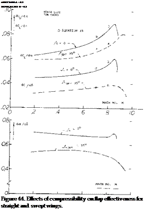
Подпись:where $2 = Jl – M2 cos2y and/v is the angle of sweep. At aspect ratios larger than 3 and below the critical Mach number, equation 55 shows good agreement with test results as illustrated on figure 55 for the variation of dCL / dot with M. When flaps are installed on such surfaces, these characteristics with Mach number of dC/d6 can also be found with equation 55 by using dCL/d6 instead of dCL /dot. As shown on figure 44, good agreement is also obtained with test and theory for the effects of compressibility on flap deflection. Since do(/dCL and d6/dCL are dependent on the same factor as a function of M, the variation of the ratio of dot /dS with Mach, number is essentially flat up to the critical, as illustrated on figure 44. Above Mcr the flap effectiveness ratio decreases in the same manner as for the two dimensional case,.
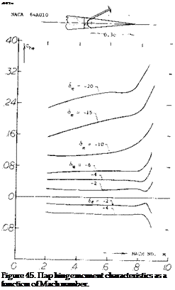
Подпись: .002c Figure 45. Пар hinge moment characteristics as a function of Mach number. Hinge Moment – Mach Number. The flap hinge moment coefficient variation with Mach number is given on figure 45 for a sealed flap configuration (51,g). At cx’ = 0 and low deflection angles the hinge moment coefficent is nearly constant up to Mach numbers just below the critical. At flap angles above 10 , C increases with Mach number approximately as would calculated using the Prandtl-Glauert correction. It would appear that up to the critical Mach number the section hinge moment derivative C for control devices should then be corrected in accordance with the P-G rule, thus
(56)

The above equation should hold up to the critical Mach number of the section, which will be a function of the section type and deflection angle.

Critical Mach Number. The critical Mach number of the control surface determines where the flap effectiveness becomes non-linear, as illustrated on figure 45. Thus to obtain the desired characteristics, the control surface is designed with a critical Mach number. This is done by choosing the proper sections and planforms to give the necessary high critical Mach number characteristics. As shown in Chapter VII, section camber and thickness ratio should be low for high levels of Mc r. Whereas in Chapters XV and XVII a high sweep angle and a low aspect ratio are needed to obtain a high critical Mach number

X – ROLL CONTROL

CONTROL-FLAP CHARACTERISTICS AT HIGHER DEFLECTION ANGLES

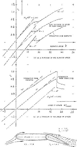
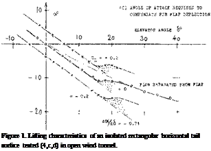
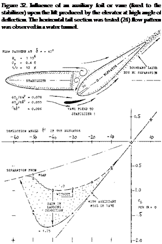
Подпись: Figure 32. Influence of an auxiliary foil or vane (fixed to the stabilizer) upon the lift produced by the elevator at high angle of deflection. The horizontal tail section was tested (24) flow pattern was observed in a water tunnel.

LIFT-CURVE SLOPE. At flap deflections exceeding the critical angle, a control surface still has a defined lift-curve slope, as long as the flow remains attached to the forward part of the foil section. Figure 33(A) shows that the slope is, somewhat higher than that of the sur­face with fully attached flow, within the range of chord ratios below 0.3. It seems that the flap has in this case, an effect similar to that of a blunt trailing edge which is known to improve lift-curve slope as well as maximum lift. At chord ratios above 0.3, the slope decreases considerably.

FLAP EFFECTIVENESS. As demonstrated in figures 1 and 18, the lift of a flap continues to increase, after passing through a more or less pronounced dip, as the deflection is increased above the critical angle. The same graphs also suggest that the lift produced by a flap, under conditions where the flow is separated from its suction side, that this lift increases very roughly in pro­portion to the sine of the flap angle (23). It is thus pos­sible to approximate statistically and for practical purposes, the effectiveness of a flap above its critical angle, by the ratio

[dC^d^im^/tdC^/dfsinck] = d(sino<)/d(sin<£ ) (39)

where dCj_/d(sinoO.=. lift-curve slope of the lifting surface in plain fully-attached flow. Evaluation of ex­perimental results, as in figure JJ(B), shows that this ratio is related to the effectiveness as in figure 2. The ratio of the two ratios, also plotted in the graph, is be­tween 0.6 and 0.7. At chord ratios approaching zero (as in tabs» the effectiveness ratio in figure 33(B) coin­cides with that in

Подпись:THE PITCHING MOMENT due to deflection of flaps with separated suction-side flow, may also be interpo­lated by means of a sine function. Approximate results of this type are plotted in figure 33(C). In comparison to those in figure 4, pitching moments due to separated – flow flaps, are only 1/2 or possibly 2/3 of those in at­tached-flow condition. The moment obviously corre­sponds with the effectiveness ratio.

Подпись:Подпись: HINGE MOMENTS at very high angles of attack, as they are encountered during spinning (25) are much higher than those represented by dC^/dCj_ in figure 7. Disregarding some discontinuity directly within the range of stalling (separation), the moment roughly v aries as — C^ ~ sin2c< (39) approaching the order of -.5 at 0^= 90° . As a function of flap deflection (with the flow past the forward part of the foil section still attached) hinge moments at higher angles as indicated in various graphs may be approxi-mated by Cp^-sincS. Results (for zero angle of attack) as plotted in figure 34, vary as a function of the flap chord ratio, in a manner similar to an average curve derived for attached flow condition. Within the range of practical chord ratios, the derivative (on 6 in degrees) is in the order of С^° ^ — .012, depending on parameters as discussed in connection with figures 7 and 8. In separated condition, hinge moments are 20 to 60% higher than in fully attached flow. As seen, for example in figure 21, the balancing effect of an overhanging nose is greatly reduced. The derivative of such flaps is around CH^ = -.01°.
“Tabs” are small-si2:e auxiliary flaps attached to, or part of the trailing edge of control flaps. Hinge moments can efficiently be changed by tabs.

MECHANICS OF TRAILING EDGE TABS are basi­cally the same as those of control flaps. We thus find:

their effectiveness or influence upon lift in figure 2,

upon longitudinal or pitching moment in figure 4,

their own hinge moments in figures 7 and 8.

CONTROL-FLAP CHARACTERISTICS AT HIGHER DEFLECTION ANGLES

As illustrated in figure 35, trailing-edge tabs can be used in 5 different ways, to modify the characteristics of control surfaces.

(E) INCREASING THE HINGE MOMENT

control"""*

Figure 35. Sketch showing various basic uses
of trailing-edge tabs.

CONTROL-FLAP CHARACTERISTICS AT HIGHER DEFLECTION ANGLES

CONTROL-FLAP CHARACTERISTICS AT HIGHER DEFLECTION ANGLES

THE HINGE MOMENT of the tab proper will be dis­cussed later. The influence of the tab upon the hinge moment of the control flap to which it is attached, is theoretically (30) a function of the flap-chord ratio. The influence of viscosity in combination with foil-section and flap shape, evidently obscures that of the flap-chord ratio. Results for ratios between 0.2 and 0.5 are plotted in figure 36, as a function of the tab-chord ratio. De­viation from theory is largest within the range of tab – chord ratios below 0.1. Realistic results might be ap­proximated by

(dCH/d<*tW = "k (ct/c-f} (40)

where к = 0.05 or = 0.06 applies to smaller flap-chord ratios (in the order of 0.2) and to heavier boundary lay­ers, and к =. 0.07 or = 0.08 to larger flap-chord ratios (in the order of 0.4) and to smooth configurations at higher Reynolds numbers. For tab-chord ratios in the order of 0.2, the variation of the flap-hinge moments due to tab deflection, is thus roughly proportional (a) to the tab angle, and (b) to the tab-chord ratio (32). Since a flap with a chord equal to that of the foil section, is simply a plain “wing” surface, the pitching moment as in figure 4, is realized to be the equivalent of a hinge – moment. Points included in figure 36, approximately agree with those obtained for conventional flap-chord ratios.

EFFECTIVENESS. To be sure, deflection of a balanc­ing tab (in the direction opposite to that of the control flap) somewhat reduces effectiveness. When, for ex­ample, using a tab with c^ = 0.1 c^, geared so that — 6 , the reduction of dcx/d<S can readily be found from figure 2. Assuming that do^/d6 ~ (c^ or c^)/c, as it is roughly true within the range of small chord ratios, the effectiveness doc/d6, and lift per degree of deflection produced by the control flap, are reduced by ^ 10o/<? Therefore, in the example above, both tab angle and flap deflection should be made some 10% larger, in order to keep Cj_ = constant.

LINKED-TAB BALANCE. When gearing or coupling the tab in the manner as illustrated in figure 35(B) it automatically deflects (from the control-flap chord) when moving the flap, in a direction opposite to this motion. Hinge moments produced by the tab then tend to balance those of the flap. For example, for c^/c =. 0.3, the hinge moment corresponds to dCq/d6 ^ —0.008 (see figure 8). It can then be found in figure 36 that, for a coupling ratio of 6^/S = — 1, a full-span tab with c^ =, 0.13 c., will fully cancel the flap’s hinge moment. Or, when selecting a tab chord c^, = 0.1 c^ for example, or reducing the tab span to 0.10/0.13 = 0.77 times the flap span, or by reducing the coupling ratio from 1.0 to 0.77, the hinge moment will be reduced to (100—77) = 23%, in the example considered.

REDUCTION OF HINGE MOMENTS. Figure 37 shows hinge moments of two horizontal tail surfaces as a func­tion of: (a) size (chord) of the linked tab; (b) deflection ratio of the linked tab. — Moments can be reduced “easily”, for example by means of a tab with c^/c^ =

0. 1 and a deflection ratio between 0.5 and 1.0. Figure 38 demonstrates that linked-tab balance is effective, not only in the case of a plain flap, but also in combination with an internal balance. Hinge moments can thus be reduced down to a few percent of the original function. [85] [86] [87] [88]

CONTROL-FLAP CHARACTERISTICS AT HIGHER DEFLECTION ANGLES

Figure 38. Influence of a linked trailing-edge tab upon the lift and hinge-moment characteristics of a tail surface.

BOOSTING HINGE MOMENTS. Full cancellation of the control moment is hardly ever desirable. In fact, there have been small and low-speed airplanes (and there seem to be some sailplanes) where stick forces in the longitudinal direction are increased by adding a tab to the elevator, geared in such a manner that it de­flects in the same direction as the elevator; see part (E) of figure 35. Three things are accomplished in this way:

(a) hinge moments are suitably increased (whenever this is desirable); (b) control effectiveness is somewhat increased; (c) longitudinal stability of the airplane is improved.

LEADING TAB. An interesting application of a linked trailing-edge tab is shown in figure 39. The elevator is basically overbalanced by means of a 50% overhang­ing nose. However, the tab is linked in such a manner that it deflects in the same direction as the elevator flap. The derivative is then made negative (stable):

(a) by the leading deflection of the tab, thus counter­balancing the overhang; b) to a degree by the reaction in the elevator to the tab’s hinge moment. The linkage ratio 6j./8 as recommended in the conclusion of (37) is 0.5. The mechanism described also has the advantage of providing increased effectiveness, so that a lesser deflection will be sufficient to obtain a certain lift co­efficient. It can also be noted that is positive. This means that longitudinal stability of the airplane is not reduced, but slightly improved, when leaving the control stick free.

d#/d6

—■ о ________________

<

э ——

(A) EFFECTIVENESS

dCL/doP= O.06 —(———–

LEADING TAB ANC-L: —— ,—– 1—- 1—— 4—–

CONTROL-FLAP CHARACTERISTICS AT HIGHER DEFLECTION ANGLES

Figure 39. Effectiveness and hinge moments of a

horizontal (or vertical) tail surface as described in the text, loaded by a leading tab (37).

STICK-FREE CONDITION. In a tabbed configuration where the hinge moment is reduced to nothing, the con­trol flap will simply move to a certain limiting position (to a mechanical stop or to a point where the flow sepa­rates from the flap’s suction side). Quantitatively, com­bination of equations (27) and (28) indicates that

Д(dcx/dCL) = +(d<x/di ) (dCH /dCL)/(dCH /d& ) (44)

The influence of the tab upon (dC цЛіб ) corresponds to

A(dCH/d6)= (6t/8 )(dCH/d6t) (49)

where (6^/6 ) =. coupling ratio (negative) and (dC^/dd^) as in figure 36 or in equation (40). Using that equation, the reduction of the hinge moment is found to correspond to

A(dCH/d<$°) = к (St/6 ) (ct/Cf) (50)

To simplify discussion, we may also assume that the coupling ratio be 8^/8 =— 1, so that the chord ratio (Qfc/Cf) becomes the measure for the tab effect. To arrive at quantitative results, we will consider two dif­ferent control-flap configurations:

(a) an aileron (or horizontal-tail) installation with:

Cf/c = 0.2; do(/d8 = 0.45; doC’dC^ = 15°

(b) a horizontal (or vertical) tail surface with:

cf/c = 0.4; da/d6 =» 0.70; do(/dCL = 20°

where (dot/dC^) is meant to be for fixed-control con­dition. Using equations (49) and (50) in conjunction with values taken from the various graphs, stick-free lift curve slopes have been computed for the two cases. Figure 40 presents these values as a function of the tab size. The loss of stabilization can be considerable, particularly in the tail surface considered.

CONTROL-FLAP CHARACTERISTICS AT HIGHER DEFLECTION ANGLES

Figure 40. The stick-free stabilizing effect of

(a) an “aileron” section with c^/c — 0.2

(b) a tail surface with c^/c — 0.4 computed as explained in the text.

0.0(o I I ‘ I I

CONTROL-FLAP CHARACTERISTICS AT HIGHER DEFLECTION ANGLES

Figure 41. The stick-free stabilizing effect of tab-balanced control surfaces as a function of the flap-chord ratio.

FLAP SIZE. The most important parameter affecting stabilization is the chord ratio of the control flap. Using the same functions as above, we have computed the stick-free lift-curve slope of a horizontal (or vertical) tail surface similar to that in case (b) above, but with varying flap-chord ratio. Figure 41 shows the lift-curve slope, as a function of the chord ratio, with balancing trailing-edge tab, geared at a ratio so that the hinge moments are reduced to 1/2 and to 1/5, respectively. The loss of stick-free stabilization is again seen to be very considerable. Of course, small flaps may not be sufficient in regard to the maximum lifting or com­pensating effect they are expected or required to pro­duce. Unfortunately, the stabilizing effect of tabbed tail surfaces reduces more and more as the flap-chord ratio is increased. In addition, it should be realized that reduction of “hinge moments” to 1/2 or to 1/5 as assumed, is not really proper. These moments grow in proportion to the square of the flap chord. Accordingly, a small flap might not need any balance at all, while it might be desirable or necessary to reduce the torque of a larger flap, not just to 1/5, but possibly to 1/10. A line connecting points of equal hinge moments (equal in feet-pounds) is shown in figure 41, thus demonstrating the fact that the stabilizing effect of geared-tab control surfaces reduces very strongly, after exceeding a cer­tain range of small flap-chord ratios.

SERVO CONTROL. Deflection of a tab (rather than of the flap itself) by means of some small control force as in figure 35(C) can be utilized to move larger-size con­trol flaps (elevators, rudders, ailerons). This type of servo system has been tried on ship rudders, in an ef­fort to reduce the heavy steering machinery usually re­quired (39). In airplanes, the servo-tab system has been used in a number of larger airplanes (40) to operate the rudder. The straight-forward system has a number of drawbacks, however: (a) it will not work at higher deflection angles because of flow separation; (b) it may

fail at low speeds where mecnanical friction will inter­fere; (c) it will reduce stick-free stabilization considera­bly (36); (d) the doubly-linked system can invite flutter trouble (44); (e) there is a time lag involved in the oper­ation (41,b). — Regarding the last point, dynamic be­havior (45) is as follows. After sudden deflection of the tab, the flap assumes the proper position almost aperi – odically, but after a delay in the order of 1 second (as tested on a larger than full-scale model). The delay is proportional to V I/q, where I = mass moment of iner­tia and q = dynamic pressure. When suddenly releasing tab and flap, both components oscillate several times, before coming to rest in the balanced position. — Never­theless, the aerodynamic mechanism of servo-tab con­trol deserves to be presented.

REDUCTION OF TORQUE. A servo-tab system can be considered to be a type of fluid-dynamic balance. The tab deflection required to move a control flap (within the linear range of their characteristics, and at Cj_ =. constant » zero) is found from equating their hinge moments:

(dCH/d6 )$ ^-(dCH/d6t (52)

For assumed chord ratios of c^/c = 0.4 and c^/c*. =. 0.2, for example, the deflection-angle ratio would be

<^/<S = —(dC^ /d6 )/(dC ц /d<^ ) ^ —0.5 (53)

where the moment due to tab deflection is obtained from equation (40) for c^/c ^ 0.2 (0.4) = .0 8. The control moment (at the stick) required to deflect the tab, in comparison to that of the control flap without any bal­ance, approximately corresponds to

(servotab)/(plainflap) = —(6^/6 )(c^/c^f (54)

which is equal to 2% in the example considered. Theo­retical possibilities of this system thus appear to be great (41). [89] [90] [91] [92] [93] [94]

CONTROL-FLAP CHARACTERISTICS AT HIGHER DEFLECTION ANGLES

and as calculated (see text).

FULLY-MOVABLE TAIL. Figure 42 shows character­istics of a fully movable servo-tab operated tail sur­face. We want to determine the control forces re­quired. Since there is no fixed part (fin or stabilizer) we can consider the hinge moment of the surface either as that of a flapped section with c^/c — 1.0, or as longitudinal (pitching) moment of that section. To keep the notation as in control flaps, use of figures 7 and 8, at c^/c = 1 is recommended. A simplified analysis is possible, however, through consideration of the location along the chord: (a) of the lift due to angle of attack; (b) of the additional (negative) lift due to deflection of flap or tab ( whatever name we want to give in this case). — The component under

(a) was experimentally (38,c) found to be at ^ 0.225 of the chord. For the hinge location at 0.15 c (see sub­script “x”) the moment arm of (a) is then 0.225 — 0.15 =. 0.075; and the hinge moment of the plain foil cor­responds to dCm)C/dC^Q = — 0.075. When using the servo flap (or tab) to deflect the surface as a whole, the longitudinal moment due to lift must obviously be cancelled by that due to deflection of the flap. In order to obtain the same lift coefficient, o< has to

be somewhat larger, however, than in the plain foil; the ratio of the angle is

(c^+Ac*)/c* = 1 —(dcx/d<S ){h/o()

which is 1.26 for the configuration considered. In a simplified analysis, we will assume that the lift dif­ferential produced by the flap has its center of pres­sure at 0.5 chord (as explained in connection with figure 6). The moment arm of the due-to-flap force is then Ax/c = ACm/ACL = 0.50 – 0.15 – 0.35, in the case considered. Since AC^/C^ = (1/1.26) —1 = —0.21, the hinge moment due to flap – or tab deflection is

dCm*/dCL = dCH/dCL= +0.35 0.21 = +0.074 (56)

This value is sufficiently close to that as tested. The re­sults in figure 42 have thus been checked by analysis.

TAB-HINGE MOMENTS (at the tab’s hinge line) are usually very small; see figures 7 and 8 at cp/c below 5°/<? and consider moment proportional to c£ . Considering the servo-control flap as in figure 42, its torque can be determined through the use of equation (40). As a func­tion of C^, the flap’s or tab’s resultant hinge moment corresponds to

(dCH /dCL )t = (dCH /dCL) + (dCH /d6 )t/(dC,_ /dA

where (dC|_/dd ) to be computed, or equal to 0.013 as tested for the configuration in figure 42. Using values picked from figures 7 and 8, the variation of the tab hinge moment is found to be

(dCH /dCJ ^ 0 + 0.008/0.013 = 0.6 (58)

This derivative is based upon flap or tab chord. In order to make a comparison with the hinge moment of the plain foil, the result must be multiplied with (c^/c) = 1/100. The tab-moment derivative, referred to total foil chord, is thus 0.006, which is some 8% of that of the plain foil balanced at 0.15 of its chord. Consider­ing the tab deflection required, corresponding to 6^/6 = — 0.87, the control moment (in the steering column) required for servo-tab operation, will only be

0. 87 (0.08) 7% of that required to move the unbal­

anced control surface to the same lift coefficient.

BALANCE OF TAB TORQUE. Boundary layer thick­ness reduces the tab effectiveness. Gaps around the tab’s hinge axis are also undesirable. As far as hinge moments (around the same axis) are concerned, refer­ence (30,h) demonstrates that an overhanging-nose type of balance can be very effective, in a manner and to a degree similar to what is explained in a previous section on this subject.

LINKED SERVO SYSTEM. As stated in the beginning, simple servo-tab control has serious operational dis­advantages. In fact, this svstem is no longer used. Con­trol characteristics were substantially improved, how­ever, by suitable mechanical coupling between flap and tab. One such system is illustrated in figure 35(D). Be­cause of the lever linking (but not connecting) the actuating rod with the flap’s hinge point, a certain moment can be transferred to the flap and not only to the tab. The mechanism can be understood by consider­ing limiting conditions: (a) when keeping the flap fixed, the control rod causes a deflection of the tab; (b) when keeping the tab fixed (against the flap), the control rod causes directly a deflection of the flap. — The con­trol force of the linked servo system corresponds to the total derivative

dCH (dCH /dA )l +(dCL /d6 )(dCH /dCL)0

d£ l-[K(cf/ct)2(b/bt)(dCH/d<g )/(dCri/dd)t]

where bt/b = tab-span ratio (which might be less than unity and К mechanical coupling ratio between tab and flap in stick-fixed condition. This ratio К = di/d^ is negative, К ж –0.5 in the configuration as in figure 35(D). Selecting average values for the derivatives to be used in the equation, that configuration is expected to operate at a control force which is only 1% of that of the same flap without balance

SPRING-TAB CONTROL. The servo-tab system in figure 35(C), is based upon aerodynamic forces and thus dependent upon dynamic pressure and flying speed. Replacing the actuating element in that system by a mechancial spring and providing suitable stops, servo operation begins after exceeding a minimum hinge moment (in feet-pounds) and it terminates upon reach­ing a certain control force (in pounds) corresponding to loading and elastic constant of the spring element used. Such a system is as in figure 35(D). When moving the control stick, the tab is deflected first (compressing the spring element), thus causing the desired deflection of the flap in a manner similar to that of a simple servo – tab system. Upon reaching a certain limiting torque, either because of high dynamic pressure or at larger angles of deflection (when flying at lower speeds), the control lever goes against a stop; and the flap is then directly controlled by rod and stick. The theory of this system has been worked out (49); considerable experi­mentation is reported (50). Advantages are as follows:

(a) Stick-free stability is not affected, particularly when the spring-tab system is preloaded, (b) Time lag and “sloppy” performance are eliminated, (c) Overcontrol­ling (due to small control forces) is prevented, (d) In high-speed pull-out maneuvers, stick force is (or can be made) proportional to acceleration, (e) Whenever necessary, the control flap can be moved to high angles of deflection (such as during the landing maneuver).

Подпись:CONTROL FORCES. As far as control moments are concerned, it may be assumed that tab torque ^ (ёСц/ёб)^, while disregarding the influence of cX or C^ and 6. The contribution from the direct displace­ment of the flap against the spring element, is propor­tional to the spring constant. For an extremely weak spring, we obtain the small control forces as discussed above for the “linked” servo system. For an extremely stiff spring, the control moment is equal to that of the flap without tab assistance. With the control lever against one of the stops and the tab in the correspond­ing end position, the hinge moment is that of the flap without balance, minus a differential corresponding to the final tab deflection. Various modifications of the system are possible. Examples for stick forces obtained through such arrangements are presented near the end of the “aileron” chapter.
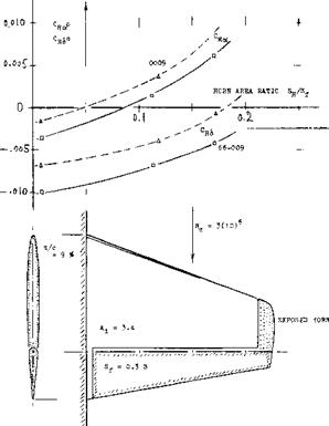
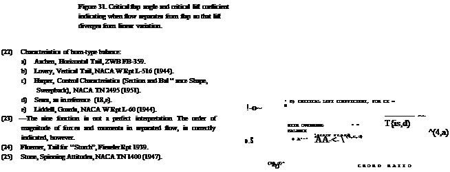
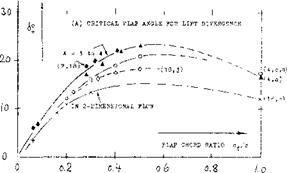
 

CONTROL-FLAP CHARACTERISTICS AT HIGHER DEFLECTION ANGLES

Figure 30. Exposed horns as tested by NACA (22,c) on two different foil-section shapes.


At an angle of deflection, say between 10 and 20° , the flow usually separates from the suction side of trailing – edge flaps. On the other hand, all control flaps used in conventional airplanes, are usually designed so that they may be deflected to angles, say between 25 and possibly above 30 . Characteristics at such high angles are as described in the following section.

THE CRITICAL FLAP ANGLE, where the lift pro­duced by deflection starts to deviate from the linear variation, as for example in figure 1 or 18, is a function of section shape, type of balance, angle of attack, aspect ratio, of other geometrical parameters as well as of the viscous conditions of the fluid flow. Figure 31 presents critical flap angles, for zero angle of attack, as a function of the flap-chord ratio: The critical angle and the corre­sponding lift coefficient increase with the chord ratio; and they reduce to nothing as the flap chord is decreased to zero. The angle reaches a maximum (indicating optimum section camber due to flap deflection) at Of/c somewhat above 0.5. — The critical lift coefficient is comparatively independent of the aspect ratio. De­pending upon section shape, maximum lift coefficients obtained through flap deflection, at zero angle of at­tack, are between 0.8 and 1.2.

  CONTROL-FLAP CHARACTERISTICS AT HIGHER DEFLECTION ANGLES

o>2- о A


CONTROL-FLAP CHARACTERISTICS AT HIGHER DEFLECTION ANGLES

INFLUENCE OF FLAP-SECTION SHAPE

As explained before, foil section thickness has an in­fluence upon control-flap characteristics. It has been discovered, however, that the angle at the trailing edge, included by upper and lower flap side, and other vari­ations of flap-section shape are more directly responsible for such effects than the foil thickness ratio. Various shape parameters are discussed in this section.

SECTION THICKNESS. The control derivatives of a flapped and tabbed 0015 foil section are presented in figure 12. In comparison to other sections with thick­ness ratios between 9 and 12%, the following conclusions can be dfawn:

(a) The lift-curve slope is reduced, corresponding to section thickness ratio. The influence of a 0.5% hinge gap on dCL/do( is noticeable.

(b) In sealed condition, the effectiveness ratios do</d<S, both of flap and tab, are “normal”. The influence of a hinge gap is considerable.

FLAP CHARACTERISTICS : lo<./d^ = 0.46 (0.5S )

dCm{dCL = +.020 (+.020)

dC^d*0 = -.0075 (-.008)

dCH//dCL = "•°25 C"-02*)

dCg/doP = -.oo23 (-.0022

dCg=dS° = -.0063 (-.008)

ГАВ CHARACTERISTICS :

dof/dSt = 0.21

dCH/d^t = -*010

dCH/d^t = -*°°5 FLAP AND TAB NEUTRAL : dCj/doP = 0.089 (0.096)

STICK-FREE (TAB NEUTRAL) : dCj/doP = 0.075 (0.080)

VALUES IN PARENTHESES

ARE FOR SEALED FLAP GAP

(c) Подпись: і The dCm/dS derivative fits into the pattern as in figure 4.
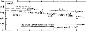
(d) The value of dC^j /dC(_ is low (see figure 7). This is evidently a true thickness and/or trailing-wedge effect.

(e) The values of dC^/d6 , for flap and for the tab, are average (see figure 8). With open hinge gap, the flap moment is noticeably reduced.

(f) The value of the stick-free lift-curve slope is com­paratively high, evidently because of the derivative as under (d).

All in all, characteristics of this 15^ thick section are thus not too much different from those of sections with smaller thickness ratios, although flow pattern, forces and moments are evidently somewhat more sensitive as to hinge-gap interference.

Подпись: Figure 13. Variation of flap thickness ratio and of flap shape as a function of section parameters.

TRAILING-WEDGE ANGLE. Modern laminar-type and high-speed foil sections have (if with “true” 6-Series contour) a hollow (cusped) afterbody shape. Their trailing-wedge angles are, as a consequence, smaller than those of other, more conventional sections. One and the same trailing-wedge angle can thus be con­nected either with a bulging or a hollow flap shape. Figure 13 shows three different ways of changing the shape of a control flap together with that of the foil section: [81] [82] [83] [84]

Figure 12. Control characteristics of a configura­tion based on 0015 foil section, tested (15,f) in two-dimensional flow.

(a) When changing the section thickness ratio, the flap shape (thickness) varies accordingly.

(b) A similar variation is obtained when shifting the position of maximum section thickness along the foil chord, back or forth.

(c) As mentioned above, certain foil sections have a cusped (hollow or concave) shape in that portion of the chord where flaps might be installed. For example, a 63-010′ section (in its original and true form) Avill thus result in a flap shape considerably different from that in a 0010 section.

INFLUENCE OF FLAP-SECTION SHAPE

TRAILING – WEDGE ANGLE

(A) SECTION THICKNESS

INFLUENCE OF FLAP-SECTION SHAPE

(B) LOCATION OF MAXIMUM THICKNESS

(C) AFTERBODY SHAPE

Of course, the flap shape can also be modified by will­ful deviation from the true section contour (as in figure 14 for example). In all these cases, the included angle (2e) at the trailing edge, which we may call trailing “wedge” angle, can statistically be used as a measure for thickness (at the hinge line) and/or curvature (at the sides) of the flap. — Experimental derivatives from various sources are plotted in figure 14 as a function of the trailing-wedge angle. The lift-curve slope (for 6 =r constant =. zero) reduces as the wedge angle is increased. The flap-effectiveness ratio (see part ‘B’ of the graph) reduces also. For example, when increasing the wedge angle from 10 to 20° , the flap’s lift-curve slope dC^/d6 reduces, possibly to 0.95(0.94) ^ 90°A


0.12-


-F


INFLUENCE OF FLAP-SECTION SHAPE

0 L 0


(A) 2-DIMENSIONAL LIFT-CURVE SLOPE


TRAILING WEDGE ANGLE (2e)°

4———— 1——— T———– 1——— 1—

10 20 30

INFLUENCE OF FLAP-SECTION SHAPE

(C) STICK-FREE LIFT-CURVE SLOPE


HINGE MOMENTS. Parts (D) and (E) of figure 14 show that the magnitude of flap-hinge moments de­creases considerably (and progressively) as the trailing – wedge angle is in-creased. In fact the due-to-lift derivative is reduced to zero at wedge angles between 15 and 25° ; and it crosses over into the positive” region above these angles. The magnitude of the due – to-deflection derivative (in part ‘E’ of the graph) re­duces also appreciably, although it may not necessarily reach the zero line. When comparing the hinge moment ratios as in figure 13 with those in figures 7 and 8, it can be concluded that all variations can readily be ex­plained on the basis of what the trailing-wedge angle stands for. The conclusion for the practical designer is that thick and convex foil-sections and “bulging” flap shapes result in low hinge-moment derivatives, while thin and hollow (cusped) foil and flap shapes, i. e. with thin trailing wedges, can be expected to produce hinge moments approaching the theoretical functions.


INFLUENCE OF FLAP-SECTION SHAPE

o, o8 .

– dCl

" da?

o. o 4- –

0


Cf/C = 0.4


TRAILING WEDGE ANGLE (2t)°

—- ,——– 1——– 1-

2o Зо


10


STICK-FREE CHARACTERISTICS are a consequence of the hinge-moment derivatives. Part (C) of figure 14 shows that the stick-free (zero-moment) lift-curve slope increases slowly, as the trailing-wedge angle is increased. In other words, the stick-free stabilizing effect of a (mechanically balanced) tail surface can be increased by increasing the wedge angle. It is to be noted that the lift-curve slope is equal to that in stick-fixed condition, at the wedge angle for which dCH /dC^ = zero. Beyond that angle, the slope increases further, which means that the flap moves by itself against the oncoming flow, upon increasing the angle of attack.


Figure 14. Influence of flap thickness and shape, as measured by the trailing-wedge ang] upon the characteristics of plain flaps.


INFLUENCE OF FLAP-SECTION SHAPEINFLUENCE OF FLAP-SECTION SHAPEINFLUENCE OF FLAP-SECTION SHAPE

INFLUENCE OF FLAP-SECTION SHAPEПодпись: ,. о.з % о an INFLUENCE OF FLAP-SECTION SHAPEПодпись:INFLUENCE OF FLAP-SECTION SHAPEПодпись: dCj/do^ dcx /d& dVdCL dCg/dS0 40l/do?r«. 0.098 0.57 -0.090 -.0085 0.066 | 0.10) 0.56 -0.080 -.0071 0.059 I 0.09t 0.50 -0.033 -.0045 0.068 0.090 0.54 -0.011 -.0025 0.106 -тштт> Подпись: R0 = 3(10)6Подпись:

sufficient thickness ratio, the tangential components of the pressure forces do produce a hinge-moment component. Positive pressure forces on the pressure side, and negative ones on the suction side, form together a force couple, the direction of which is such that it tends to move the flap against the on­coming flow.

(b) Tested pressure-distributions due to angle of at­tack and due to flap deflection (17), are plotted in figure 16 for a beveled flap shape. The two deriva­tives show practically identical loops near the trail­ing edge; and these loops, representing “negative” hinge-moment components, are obviously responsi­ble for much or most Ы the reduction (and possibly reversal) of the hinge moments evident in figure 13.

THE FLOW PATTERN connected with any pressure – distribution loop of the type as in figure 15, is most likely as follows:

Подпись:

BEVELED TRAILING EDGES. Since flap shape, as described above, considerably affects hinge moments, suitable variations may be used to change the level of these moments. It can be convenient, for example, in a finished airplane, to exchange an elevator or rudder with a somewhat differently shaped design. Figure 15 illustrates several possible modifications of a flap; con­sequences are tabulated. We can see that neither thicken­ing the trailing edge, nor rounding of that edge (with a comparatively small radius) has much of an effect upon hinge moments (although the parasitic drag is increased). However, curvature in form of an elliptical contour, or beveling of the thickened trailing edge (to an enclosed angle of 20 or 30° ) reduces the hinge-moment deriva­tives considerably. This type of beveling (necessarily combined with increased flap thickness) is obviously a form similar to convex (bulging) flap shape, id est with the location of curvature far aft.

PRESSURE DISTRIBUTION. Hinge moments are the result of pressure distributions; and those distributions evidently change appreciably, not just in size but also in character, as thickness ratio, trailing-wedge angle or flap curvature are varied. Explanation of reduced and reversed hinge moments is possible by considering two components:

(a) Pressure forces on the 1/2 cylindrical forward edge of the flap cannot produce any hinge moment; and those along the flanks could not either in a really thin flap (id est a flat plate). However, in a flap with

116) As a function of the angle of attack, the consequence of separation from a trailing wedge can be such that a reversal of the lift-curve slope takes place; see the chapter on “airfoil sections”.

(17) Within a limited range of the angles involved, the pressure distribution varies in linear proportion to them. The pressure coefficients can thus be presented

(a) On the suction side of convex (bulging) or beveled flaps, boundary layer material tends to accumulate “at” the trailing edge. With or without local separa­tion of the flow, the pressure, therefore, discontinues to rise to a positive value at the trailing edge.

(b) On the pressure side, the pressure gradient is es­sentially negative. Boundary layer growth (and sepa­ration) are thus prevented; and the flow follows the curvature of the flap surface. Negative pres­sures (suction) may thus develop as shown.

in form of derivatives, as in figure 16.

The flow from the upper and that from the lower side of the flap, join each other at or beyond the trailing edge at one and the same pressure level (near zero). A loop is formed in the pressure distribution, accordingly. It

can also be said that the flow pattern described is similar 7. OVERHANGING-NOSE BALANCE to an imaginary one in which the rear stagnation point is shifted around the trailing edge, onto the suction side.

FLAP CAMBER (a one-sided curvature in the flanks of a flap) is usually found only in ailerons, and is as such discussed in the chapter on this subject. Camber in the magnitude of 1% of the flap chord, produces a differ­ential ДСц « 0.024, in the direction to the convex side. Here as in all other cases of flap-section curvature the convex side is obviously subjected to a component of suction, while a hollow flap side encounters increased pressure.

“S” TYPE MOMENTS. Beveling of thickened flaps is described above and presented in figure 15, for example, as a means of reducing hinge moments. Figure 17 dem­onstrates, however, that such reduction has limitations. The low hinge-moment derivative Сц£ = — 0.0025 is restricted (in that particular example) to a narrow “c” range of less than plus or minus 5° . The amounts of suction which the lower side of the beveled portion of the flap can gain, and which the upper side can lose, are evidently reducing as the flap angle is increased. Beyond plus and minus 20° , the hinge moment ap­proaches values corresponding to = — 0.0090 which is about the level for a plain flap (see figure 8). Beveling of the type as in figure 16, obviously reduces hinge moments where they are small; and it does not materially reduce them where they are large. The “S” shape of the hinge-moment function is not desirable.

INFLUENCE OF FLAP-SECTION SHAPE

0.2

All hinge moments presented so far, are those of “plain” flaps. Elevators, rudders and ailerons of this type can be used in small and low-speed airplanes, where hinge moments or forces do not exceed a magnitude which the pilot can apply with his hands to the control stick. In larger sizes (and at higher speeds) some type of aero­dynamic balance designed into the control flaps is de­sirable or necessary: to reduce the pilot’s efforts and to prevent fatigue, to make the airplane more maneuver – able, to reduce structural strain in flaps and control linkages. The most frequently used type of balance is by means of an overhanging nose (leading edge) added to the control flap.

DEFINITIONS. When deflecting a control flap, static pressure increases on one side, and a certain negative pressure arises on the other side. Upon adding an over­hanging “nose” to the control flap (or by moving the hinge axis back) some aerodynamic balance of forces normal to the flap chord can thus be expected. Since the control effect depends upon the chord “c_p”. The length of the flap nose (cb, with “b” from balance) is defined forward from the hinge axis. This length may be expressed as a fraction, either of the total flap chord or of the chord “cp”. We have selected to use the latter definition.

EXAMPLfe. Experimental characteristics of a control surface configuration balanced by an overhanging nose, are presented in figure 18. The variation of lift as a func­tion of flap deflection and of angle of attack, is of the same type as described in connection with figure 1. Part (C) of figure 18 shows, however, that lift is reduced on account of nose balance, at higher angles of attack (such as 20° ) and at larger deflections (above 30° under the conditions as tested). As far as flap effectiveness is con­cerned, the ratio dcX^d6 corresponds to the statistical function as in figure 2. Comparison with other data (see later) indicates that the hinge moment as in part (D) of the illustration, is appreciably reduced as against that

Подпись: '■'H — o.3 Подпись:Подпись: WITHIN THE HANGS OF LINEAR VARIATION, DERIVATIVES ARE AS FOLLOWS : d'Wd0L>4 - + 0.049 (+ 0.049) dCi/doP)6 = 0.089 (0.090) dVaSO)0i, ■ - .0040 (- .0044) dtx/di)CL = 0.50 ( 0.53) aVdS°)« = - .0025 (- .0044) dCi/d4r». - 0.144 (0.144) ІОЕ/І5°>СЬ - - .0047 (- .0050) dCE/do?)j" « + .0036 (- .0010) IN PARENTHESES FOR SEALED HINGE GAP. dCj/dC^ = + 0.040 (+ 0.011)

зев FIGURE 8

+

Figure 17. Characteristics of a control flap with beveled trailing edge, tested (15,a) under two-dimensional conditions.

Подпись: Iof the same flap with only a nose corresponding to the radius around the hinge axis. The same graph also demonstrates:

(a) that the constant portion of hinge moment slope CH£ is practically the same for the angles of attack tested (between-10° and 4-20° .)

(b) that the range of deflection angles within which

the slope is really constant, is limited (be­

tween plus and minus 10 or possibly 20° , under the conditions as tested).

It should be kept in mind that the hinge-moment deriva­tives as presented in the following paragraphs and il­lustrations, are only those corresponding to the linear variation as noted in part (D) of figure 18. For hinge moments at higher angles of deflection and/or attack, see the next section.

2.0-

INFLUENCE OF FLAP-SECTION SHAPE(A) LIFT A3 FUNCTION 0? ANGLE 0? ATTACK £ = 0
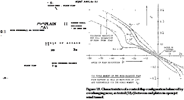
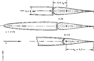
INFLUENCE OF FLAP-SECTION SHAPE

(B) STICK-FREE FLAP DEFLECTION SO THAT HINGE MOMENT * ZERO

INFLUENCE OF FLAP-SECTION SHAPE

INFLUENCE OF FLAP-SECTION SHAPE

(18) Investigation of overhanging-nose balances:

a) Gorski, САНІ (Moscow) (1930); see (4,a).

b) Goett, Elevator Shape, NACA T Rpt 675 (1939).

c) Junkers W’Tunnel Results D-7182/91 (1942)

d) Harper, Aerodynamic Balance, NACA T’N 2495,

e) Sears, Control Surfaces, NACA WR L-663 (1943).

f) Purser, Correlation, NACA W Rpt L-665 (1944).

g) Bates, Tail Surfaces, NACA TN 1291 (1947).

h) Smith, Elevators, NACA T Rpt 278 (1927).

i) Bradfield, Controls, ARC RM 1420 (1931).

j) Dirksen, Tails, ZWB 359 (1935); see (4,d).

k) Adamson, Nose and Gap, ARC RM 2326 (1940).

m) Riebe, 0009 Various, NACA WR L-196 (1945).

n) Tamburello, Tail, NACA W Rpt L-41 (1946).

o) Hoggard, Flaps, NACA TN 1248 (1947).

(19) Kirste, Trav Cercle Etudes Aerot Vol 7 (1932).

OVERHANG LENGTH. Considering the effective length of the overhanging flap nose, finite thickness of foil section and flap have to be taken into account. A “plain” flap has usually a half-round nose corresponding to foil-section thickness at the hinge axis. All pressure forces on this half-circular shape are directed toward the hinge axis. As mentioned before, they can thus not contribute to balance; the corresponding nose length is ineffective. Depending upon section thickness (at the location of the hinge) and flap chord, this length can be between 5 and 20% of the chord c^. Upon in­creasing the nose length beyond this lower limit, the magnitude of the hinge-moment derivatives reduces steadily, such as illustrated in figure 19.

LIFTING CHARACTERISTICS. The results tabulated in figure 19, show that the lift-curve slope dC^/dcx is reduced when adding an overhanging nose, evidently because of the surface discontinuity (gap) necessitated. The flap effectiveness ratio do(/d6 is, on the other hand, increased so that the lift curve slope due to flap deflection dCj_/d<£ is seen to be increased, a few per­cent. In other words, within the range of small and moderate angles of deflection, a well-rounded flap nose usually improves the flow past the suction side, around the bend produced by flap deflection.

INFLUENCE OF FLAP-SECTION SHAPE

Figure 19. Example of a control surface tested (18,n) under two-dimensional conditions of flow, with three different degrees of overhang – balance, at zero angle of attack.

HINGE MOMENTS. Three different hinge-moment derivatives are plotted in figure 20 as a function of the nose-balance length ratio cb/c^. The derivative due to angle of attack (id est, due to lift) as in part (A) reduces, slowly at first, with the nose length ratio; and it reaches zero at length ratios between 40 and 50°/°. The moment due to deflection is usually more important than that due to lift. Part (C) of the graph demonstrates how dC^/d6 reduces as the length of the balancing elevator – or rudder nose is increased. Assuming that the pressure or normal-force distribution along the flap chord be triangular (reducing to zero at the trailing edge) we may qualitatively compute the hinge moment and its varia­tion due to adding a nose portion. This was done, taking into account that the first piece of overhang, assumed to be 12.5#> of the aft-of-hingc-axis flap chord, would be ineffective (see above). The semi-theoretical func­tion, included in graph (C), confirms the general charac­ter of the experimental lines.

CHARACTERISTICS AT CX = ZERO. So far, all control-flap characteristics have been considered within the non-dimensional system of partial derivatives. Nor­mal forces and hinge moments at constant angle of at­tack can directly be of interest, however: (a) in the be­ginning on an airplane maneuver, when suddenly de­flecting a control flap, (b) in wind-tunnel testing, where investigation at zero angle of attack is comparatively simple. — For ex’ = zero, the complete hinge-moment derivative is

CHi = (dCH /dS k+tdCH /dCL)<5(dCL/doc)(do9a6 )

Подпись: -.008 -.013 -.0094 -.007 -.007 -.0086 -.001 -.003 -.0096

Подпись: 0.11 °f 0.095 0.55 0.35 0.087 0.62 0.50 °f 0.081 0.66 Подпись: Figure 20. Hinge-moment derivatives of horizontal tail surfaces with A — 3 to 4, as a function of overhanging-nose balance

Because of the slope dC^/doC, the aspect ratio and other conditions affecting lift (such as those of a wind tunnel) have considerable influence upon the derivative; see (8).

NOSE SHAPE. Results of systematic flap or nose-shape investigations are plotted in figure 21. Principle results are as follows:

(a) Considering hinge moment as a function of deflec­

tion, the partial derivative dC^/dCj_ (as in part ‘A’ of figure 20) is of lesser importance. The com­plete derivative, id est at eg — zero, there­

fore, provides quick comparison between different shapes, types of balance, and flap-chord ratios — provided that aspect ratio and test conditions are kept constant.

(b) As far as lift is concerned, it can be stated that the slope dC_/d& is on the average not affected by overhanging-nose balance. Depending upon nose shape, the flow around the bend at the suction side, toward the flap, may be somewhat improved or somewhat obstructed, however, in comparison to that past a plain flap. As a consequence C^(6) is not always a straight line.

(c) Подпись: - ,C88 Подпись:The maximum lifting effect (C^mx at eg =- 0) is also a function of nose shape.
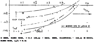
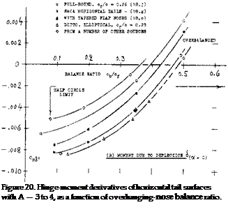
Подпись: □ 0009, BLUNT NOSE, = 0.2 (I8,m) • КАСА. 0009, ELLIPTICAL - (18,е) ■ DITTO, BLUNT NOSE, cf/o = 0.3) Подпись:

(d) Tapered nose shapes (giving the flap a more or less sharp leading edge) do not readily come in contact with the outside flow. Their balancing effect cor­responds to the local pressure differential between upper and lower side of wing or tail surface.

(e) Well rounded and “full” nose shapes “emerge” on one side from the contour of the foil section. Strong suction forces develop, as a consequence, reducing the hinge moment appreciably.

The suction forces arising on the emerging side of an overhanging nose provide an important fraction of the balancing effect; and it is this influence which causes much of the wide spread in the results as plotted in part (B) of figure 20. Depending upon shape, length, and deflection, the flap nose can also facilitate the flow past the bend in the suction side, so that d€^ /db slopes and maximum lift coefficients may be obtained which are higher than those due to same-size plain flaps. This applies to roughly 1/2 elliptical nose shapes. On the other hand, conditions around the bend can also be such that flow separation takes place suddenly, accompanied by a drop of the lift coefficient to a comparatively low’ level. Such termination of effectiveness is seen, for example in figure 21, beyond the deflection angle where the highly tapered nose comes out of the suction-side contour.

Подпись:HINGE GAPS. Every control flap requires some clear­ance to permit: motion free of mechanical friction. We will assume that the width of the gap between flap nose and the fixed part of wing or tail surface of an airplane, may be in the order of 1/4 inch, or 1 cm. Measured as a fraction of total full-scale chord, the gap may then have a width “s” between 0.3 and 0.6o/° of that chord. Aerodynamic consequences of hinge gaps are:
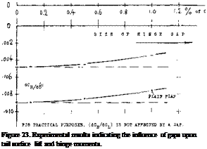
THE INFLUENCE UPON LIFT is twofold. Figure 23 shows that (dC^/dc*) as well as flap effectiveness doCd6 decreases steadily when opening up the hinge gap. This means that the lifting effect dC^/d6 may be reduced between 17 and 32°/° for the rather ex­treme gap size of 1% of foil chord. The influence upon lift of the comparatively large openings (voids) connected with overhanging-nose balance, can also be found in the tabulation in figure 19. The lift-curve slope decreases uniformly with the size of an open overhang balance. A certain interaction must be ex­pected between nose size and/or shape and the size of the control gap. Figure 24 demonstrates that the influence of a plain control gap upon the lift-curve slope is also a function of location or of flap-chord ratio.

INFLUENCE OF FLAP-SECTION SHAPE

Подпись:Подпись: 0009 (15,a) 0.2 -- of/° - 0-3 Подпись:INFLUENCE OF FLAP-SECTION SHAPEПодпись:a reduction of lift-curve slope, a reduction of flap effectiveness, an influence upon hinge moments.
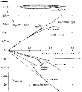
Подпись: GAP = 0.5 * о
Подпись: Figure 26. Eample of a covered internal overhanging nose balance, as tested (18,dl on the half model of a horizontal tail surface.

Подпись:Подпись:Подпись: SEALED COVERED BALANCE. Figure 23 shows a small in­fluence of presence and size of gaps upon the hinge moment due to lift. The openings (gaps) necessarily connected with the open overhanging-nose type of balance, increase the parasitic drag of a tail surface, possibly by 10°’/o. One has, therefore, tried to cover the openings, for example as in the last configuration in figure 26. It is readily understood that lifting, drag-, and pitching-moment characteristics of such configura­tions will be essentially the same as those of and due to plain flaps. Of course, the effectiveness (lift) of such “internal” balances is necessarily limited (for example, by a maximum deflection angle of 16° , in­stead of 25 or 30° ); see figure 25.

INFLUENCE OF FLAP-SECTION SHAPE

INFLUENCE OF FLAP-SECTION SHAPE

iCDfi = INCREMENT Of SECTION DRAG DUE TO CONTROL HINGE GAPS

LIMIT FOR LINEAR HINGE MOMENT VARIATION

Figure 25. Characteristics of an elevator flap, tested (18,k) with 4 different shapes of a 25% overhanging nose balance.

(20) Characteristics of internal balance:

a) See references (18,d) (18,e) (18,k).

b) Braslow, Internal, NACA TN 1048 (1946).

c) Pressure distribution derivatives see (18,m).

d) Denaci, Internal, NACA W Rpt L-432 (1943).

(21) The internal balancing nose plate can also be displaced to one side, thus permitting deflection, for example, between 4- 10 and —20°

PRESSURE DIFFERENTIAL. Balancing forces corre­spond to the pressure differential between upper and lower section side, in the small gaps at the ends of the cover plates. As derived from basic foil-section and flap theory, this differential is roughly expected to be of the form:

Дср = tydCL/doOcx + k2(dCL/dcS )t5 (38)

where dC^/d6 .= (dC|_/doO(do{/di) and where k, and k2 are constants depending upon section shape and the location of the gaps, approximately defined by c^/c. Evaluation of tested values (20.b) indicates, for example, that for cp/c = 0.2, the constants are in the order of kj = 0.40 and k2 between 0.10 and 0.15. Figure 27 de­monstrated, however, that the pressure differential be­tween the covered sides of the nose decreases rapidly, when introducing the gap required to permit free motion of the flap. Leakage across the nose gap may be pre­vented by means of a suitable seal, such as in figure 26.

/.1 * of C 4-

Подпись:Подпись: at o(= 0 <5 = io° Подпись:INFLUENCE OF FLAP-SECTION SHAPEo. H – e.£ o. t io

COVER PLATES. As described in (20,d) characteristics of an internal-type balance can also be influenced by bending the cover plates:

(a) when bending them out of the true section con­tour, the magnitude of the moments due to deflection reduce within limits.

(b) by bending the plates to within the section con­tour, the value of the moment due to deflection increases somewhat.

(c) in either case, the hinge moment due to lift (or angle of attack) changes in the direction opposite to that of the moment above.

The local pressure at and directly aft of the edge of each plate is evidently responsible for these effects.

INTERNAL EFFICIENCY. Figure 26 proves that in­ternal balance can reduce hinge moments. Of course, the balancing effect also corresponds to the length of the plate ahead of the flap; and that length is restricted through the geometry within the covered space (21), Even disregarding this restriction, the graph demon­strates that an internal balance is somewhat less ef­ficient than a comparable well-shaped open overhanging – nose. balance. The advantage of the internal type of balance is thus found in the reduction of drag as stated above.

INFLUENCE OF FLAP-SECTION SHAPE

INFLUENCE OF FLAP-SECTION SHAPE

Figure 28. Lift and hinge moment of vertical (or 1/2 horizontal) tail surface tested (22,b) with and without horn balance.

THE HORN-TYPE BALANCE, as for example in figure 28, could be considered to be a part-span overhanging – nose type. Such horns are located at the outer ends of tail surfaces. Lift and hinge moment show the familiar behavior, first a linear range of variation, as a function of flap deflection, and then a transition to a higher slope, due to flow separation from the suction side of the flap. The balancing effect is, of course, a function of chord – wise and spanwise dimensions of the horn. The simplest method of defining horn size, is the area ratio S^/S where Sj-j area of the horn, measured ahead of the hinge axis, thus including a part of the radius-type nose which every plain flap usually has.

INFLUENCE OF FLAP-SECTION SHAPE

(or vertical) tail surfaces.

THE HINGE-MOMENT derivative CHo( and the total derivative Сц£ of two horn-balanced tail surfaces are plotted in figure 29, as a function of the horn-area ratio. C^ reaches first and crosses the zero line, in a manner similar to that of the overhanging-nose type balance in figure 20. There are some differences, according to shape and arrangement of horns:

a) The two configurations, tested with “shielded” horns (figure, 28 and 29) show approximately the same slope of balance versus area ratio.

b) Exposed horns (as in figure 30) evidently have the strongest effect of reducing hinge moments, par­ticularly in regard to.

c) Depending upon shape and location of the horn,

can be made zero by an area ratio between 18 and 28%.

If in view of maneuverability, a positive (stabilizing) C ^derivative is undesirable; A shielded horn type may therefore, be used to advantage.

GUARDS. When deflecting a horn-balanced flap, the flow over horn and adjoining surface becomes disturbed and separated. As reported in (22,2) a “guard”, in form of an end plate, was placed within the gap of a configura­tion similar to that in figure 30. As a result: (a) Lift – curve slope increased some 6°/°. (b) The derivative dC^/d6 increased some 5°/°. (c) Hinge moment due to deflection reduced some 10%. — The guard evidently improves the flow pattern over the horn and along the gap as it opens up.


INFLUENCE OF ASPECT RATIO AND FORM

As pointed out before, the derivatives of control-flap forces and moments can be taken in such a manner that they are theoretically independent of the aspect ratio of wing or tail surface. Actually, a flow pattern similar to two-dimensional cannot be expected to exist at and near the lateral edges. Other deviations must be expected on account of plan-form shapes different from rec­tangular and straight, such as sweepback in particular.

INFLUENCE OF ASPECT RATIO. Lifting surfaces have tips, ends or lateral edges where the pressure distribution is no longer similar to two-dimensional. The influence of finite span upon the control character­istics is conveniently considered in terms of the aspect ratio. A systematic investigation into forces and moments of plain horizontal tail surfaces as a function of the A’ratio is specifically reported in (4,c, d). Figure 10 presents the influence in terms of the derivatives explained in the first part of this chapter. Results for chord ratios be­tween 0.2 and 0.4 are as follows:

(a) Подпись: (A) FLAP EFFECTIVENESS RATIO 4- S Подпись:The effectiveness ratio d<x/db hardly varies, down to A = 2. While a number of experimental values reported in (4,d, c) but not reproduced in figure 10-A,
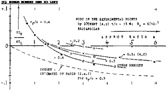
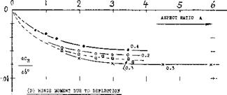
indicates a decrease of the effectiveness ratio below A = 2 or = 1, lifting-surface theory (2,f) predicts an increase to unity, as the A’ratio approaches zero.

(b) Подпись: (C) HIHGB MOMENT DUB TO LIFT INFLUENCE OF ASPECT RATIO AND FORMThe pitching moment dC^d^ reduces as the A’ratio is reduced. The change is similar to that of dCm./dCL (due to the linear lift component) as explained in the chapter on “straight wings”.
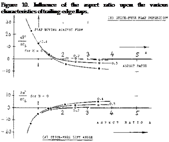
(c) The derivative dCq/dC^ reduces as the A’ratio is reduced; and it changes direction or sign, roughly between А з» 3 and = 1. The influence is still noticeable at least up to A = 5.

(d) The hinge moment due to flap deflection (at = constant) reduces in a manner similar to the pitch­ing moment under (b). Values which can, for practi­cal purposes, be accepted as constant, may be expected above A ^ 3.

(e) The deflection of a stick-free elevator or rudder (at zero hinge moment) not only reduces as the A’ratio is reduced, it can also change sign (at A between 2.5 and 1.5 as in the graph). The variation corresponds to that under (c).

(f) The increment of doC/dC^ due to stick-free con­trol flap, corresponds to the variation of the de­flection angle under (e). At and below A =. 2.5 or 1.5, the flaps of the tested configurations tend to move against the oncoming flow.

Подпись:INDUCED ANGLE. As explained in the chapter on “small aspect ratios”, the mechanism of circulation reaches a certain limiting condition, roughly at an as­pect ratio equal to unity. Below A — 1, and disregarding any “cross-flow” lift component (as at higher angles of attack), lift is produced “near” the leading edge, while the trailing edge contributes “nothing”, because of “complete” downwash. Lift and pitching moment pro­duced by,* and hinge moments of control flaps can thus be expected to decrease as the A’ratio is reduced. The variations as in parts (B) and (D) of figure 10 are thus explained. It must be noted, however, that in small aspect ratios, both the control surface as such, as the flap (when deflected) produce an additional non-linear lift component.
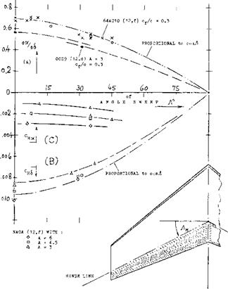
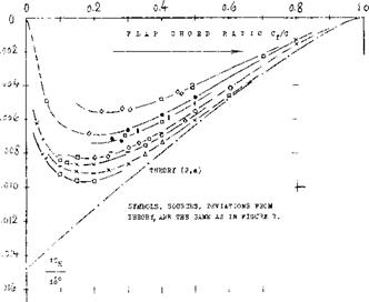
REVERSAL OF HINGE MOMENTS. Finite aspect – ratio (lifting-surface) theory in (2,f) confirms the reason­ing in the preceding paragraph. Evaluated in the form as in this text, the theory yields a hinge-moment derivative due to lift, reducing toward nothing, as the A’ratio ap­proaches zero. Part of the trend as in part (C) of figure 10, is thus explained. However, experimental results, if not below A — 2.5, then below A = 1.5, clearly de­monstrate a reversal of the moment, corresponding to a positive sign. This reversal is similar to that as found later (see figure 14) resulting from larger trailing-edge angles. It appears that the trailing-wedge effect is en­larged by the type of flow pattern past the afterbody of small-aspect-ratio wings.

SWEEPBACK. As a function of the angle of sweep, the lift curve slope (dC^/doc) of a series of wings having one and the same finite aspect ratio, reduces approxi­mately or not quite, in proportion to the cosine of the angle of sweep “Л ”; see the “swept wing” chapter. The angle of sweepback in tapered wings or control surfaces, measured in each half span at the flap hinge line, is somewhat smaller than the angle of sweep conventional­ly defined for. the quarter-chord line. It seems that the hinge-line sweep is applicable to the forces and moments of and due to flap deflection. We have, therefore, used this type of angle when plotting the experimental points in figure 11, wherever “<$ ” is involved. The deflection angle of a control flap (such as an elevator) measured in the direction of flow or flight, is only (cosA) times the angle 6 measured about the hinge axis. Tentatively, therefore, the lift-curve slope due to deflection (at con­stant angle of attack) may vary as

dCL /сіЛ ~ cos(30)

This variation is reasonably well confirmed in (12,f). As a consequence, the flap effectiveness ratio can be expected to vary as

dot/db ~ cosj (31)

Confirmation by experiments as in part (A) of figure 11, is acceptable. It is suggested, however, that the flow pat­tern is too much 3-dimensional for the lifting-line ap­proximation above.

INFLUENCE OF ASPECT RATIO AND FORM

Figure 11. Flap characteristics as a function of the angle of sweep of wing or control surface.

HINGE MOMENTS (of plain flaps) may be expected to be proportional to the lift produced by their de­flection. Therefore: dH/d6 ~ cos2A * Considering, however, the moment arm of any swept flap normal to its hinge axis, to reduce in proportion to cos. A, we obtain

C|_|£ ~ cos. A (32)

Confirmation is found in part (B) of figure 11. As far as the hinge moment due to lift or angle of attack is con­cerned, theory (12,g) predicts a modest increase as a function of sweepback. The results plotted in part (C) of the graph, confirm this prediction. The derivative, which is small in the first place, might also be considered to be independent of the angle of sweep.

PLAN-FORM SHAPE. It is explained in the chapter dealing with “straight wings”, that the lateral edges and the rear plan-form corners of a wing are important in regard to lift, and lift-curve slope. Examination of ex­perimental results shows that edges and corners also have an effect on forces and moments of and due to flaps. In particular:

The derivatives dC^/d6 and do(/d^ of a control surface having an elliptical plan form, are notice­ably reduced as against those obtained for a com­parable rectangular surface.

The magnitude of hinge-moment derivatives is re­duced; particularly dC^/dC^, thus providing in­creased (dC|_/do<) in stick-free condition.

HINGE MOMENTS OF PLAIN CONTROL, FLAPS

DEFINITIONS. The hinge moments “H” of flaps, ailerons, elevators and rudders are conveniently pre­sented in the form of the coefficient based on chordwise length, and area of the “flap” portion (measured aft of the hinge line):

Сц ~ H/(q Sf Cp); where: = Ь(с^Г (18)

In configurations where c^ is not constant, the mean of (c^)2 is the best reference length to be used for the hinge moment. There is a basic convention in the field of aeronautics to designate longitudinal (pitching) motions and moments as positive when their direction is “nose – up” (and “tail-down”). Positive deflection of a control surface thus produces a “negative” moment. When dis­cussing “large” or “small” hinge moments, the magnitude of the torque, usually resisting positive flap deflection, is meant in the following.

DERIVATIVES. Theory (2) considers a flat plate (with zero thickness) with a portion of the chord near the trail­ing edge, deflected by the angle “6”, in two-dimensional flow. When deflecting this “flap”, a hinge moment originates, corresponding to coefficients and derivatives as follows:

(a) At constant deflection angle the hinge moment varies corresponding to

CH – (dCM/dCL) CL (19)

This case applies when changing the angle of attack; and the derivative is (for most practical purposes) in­dependent of the aspect ratio.

(Ы At constant lift coefficient (id est, when compensating flap deflection in one direction, by a change of the angle of attack in the other direction) the moment cor responds to

CH = (dCH/d<0 S (20)

Note that for = constant, the induced angle of at­tack is constant. The function of dC^ /d6 as in figure 8, can thus also be considered to be independent of the aspect ratio. The two derivatives (a) and (b) appear to be the most perfect form to present hinge moments. The NACA has been using, in practically all publications, different forms, however:

(c) At constant angle of deflection, the moment varies corresponding to

= Cq^od, where Сцх = (dCq/MCL)(dCL/doO

Since dC^/doc is a function of the aspect ratio, the de­rivative grows in magnitude as the aspect ratio is increased.

(d) At constant angle of attack, the hinge moment varies as a consequence of flap deflection as

CH-CHi4 (22)

where Cp£ =. combined derivative, due to 6 plus due to Cl produced by 6 . This derivative is thus

Ch6 dCH/d6 +(dCH/dCL)(dCL/d<$) (23)

which is again a function of aspect ratio.

The derivatives (c) and (d) have two advantages. They are conveniently determined in wind-tunnel experiments; and they present the two variations of hinge moment in such a manner that their relative magnitude is obvious.

HINGE MOMENT DUE TO LIFT. Experimental results are plotted in figure 7 together with the theoretical prediction. Conclusions are as follows:

(a) Experimental moments are always smaller than those indicated by theory. Presence and growth of the boundary layer are responsible for the dif­ference. Reynolds number, surface roughness and size or shape of the control gap affect the magnitude of the derivative.

(b) The moment is sensitive to section thickness and trailing-wedge angle.

І.0

NACA HOE1TAILS A = 3.5 (I8,g) HORIZONTAL TAILS, see (4,c, d) TAIL SURFACES – OTHER SOURCES VARIOUS SURFACES (2,a)(4,h, i) TAIL SURFACES (4,j)(and(18,a) RECTANGULAR, t/c = 1656 (18,j) NACA SECTIONS (4,1) and(30,c) 2-DIMENSIONAL – OTHER SOURCES NACA 0009 SECTION (4,Ь)(18,е)

Figure 7. Hinge moment of trailing-edge flaps due to lift, for 6 — constant.

(c) The moment reduces with the aspect ratio of the control surface.

(d) It is suspected that test conditions (open-jet as against closed-type wind tunnel) have an effect similar to that of the aspect ratio.

(e) Approaching zero chord ratio, the hinge moment due to lift can become very small. A combination of small A’ratio and* large trailing-wedge angle reverses the direction of the moment altogether.

Details of the various effects listed will be presented later.

HINGE MOMENTS OF PLAIN CONTROL, FLAPS

Figure 8. Hinge moment of trading-edge flaps due to deflection, for Cj_ =. constant.

THE HINGE MOMENT DUE TO FLAP deflection (at constant lift coefficient) corresponds to derivative plotted in figure 8. Again because of viscosity and the effects listed above, the moment is less than predicted by theory. The scatter of the experimental points is considerable, if not as wide percentage-wise as in fig­ure 7. In comparison to the component due to lift, the moment corresponding to dCp/di is usually larger in realistic control configurations. Also, as mentioned before, tail surfaces predominantly operate at constant lift coefficient. For small and moderate chord ratios, figure 8, therefore, gives most of the information needed in the estimation of the hinge moments of plain elevators and rudders. [80]

HINGE MOMENTS OF LANDING FLAPS. Trailing – edge flaps, used to increase the lift coefficient of wings (see the special chapter on this subject), are a case that might suitably be considered at constant angle of attack. The hinge moment of a flap extending over the entire span of the wing, is then:

CH — CHo T(dk p/d6 )6 T(dCp/dCp)ACp (24)

where Сцс represents a certain basic moment due to shape (camber) of the foil section involved and corre­sponding to the original lift coefficient. The last term in the equation can be written as a function of the deflection angle:

A~ (dCq/dCL )(dCL/do()(do(/d6 )6 (25)

The lift-curve slope in this equation corresponds to the wing’s aspect ratio; see the chapter on “wings”. The dcx/d6 ratio is indicated in figure 2. As mentioned above, the combined derivative (equation 23) is also fre­quently reported in connection with control surfaces,

EXAMPLE. We will assume a tail surface at constant angle of attack, having a lift angle doCdCp — 16 . The chord ratio of elevator or rudder, respectively, may be Cp/c ~ 0.33. We then find from the various graphs:

(dCH /dCL) .= – 0.03; (dCH /d<S°) = – 0.007

For (X = 0 , the component of the hinge moment due to lift is then found through the use of equation (25):

A(dCH/dcS°) – – 0.03(0.58)/16 = – 0.001

The total moment (at constant angle of attack) corre­sponds to

CH£ = – 0.007 – 0.001 = – 0.008

As mentioned before, the component due to lift is but small in comparison to that due to flap deflection. It should be noted, however, that the values in figure 7 increase with the chord ratio, while those in figure 8 reduce, at chord ratios above 0.2 (eventually to zero). The derivative dC ^ / dCp could therefore not be dis­regarded in flaps with unusually high chord ratios.

STICK-FREE CONDITION. We will consider an air­plane with a control system which is completely mass – balanced and free of mechanical friction. When the control stick of that system is left free, the elevator (and/or the rudder) will assume a certain deflection angle at which the aerodynamic hinge moment is zero.

CONTINUED

Подпись: A8Подпись: 4 NACA HORIZONT’TAILS (18,g) ■ A = 3.5, & t/c = 13* (4,c) a PROM VARIOUS OTHER SOURCES о ARC - TAII SUBPACES (4,h) POLISH Htail RESULTS (4,3) HORIZONTAL SUBPACE (18,j) - NACA (4,1) WING FLAP (4,g) NACA ON 0009 SECTION (4,b)HINGE MOMENTS OF PLAIN CONTROL, FLAPSThat angle corresponds to

d6 /dCL = – (dCH /dCL )/(dCH /d6 ) (27)

Points evaluated from experiments, through the use of this equation, are plotted in part (A) of figure 9. The divergence of these points from the theoretical function is similar to that in figures 7 and 8. Below c^/c = 0.2, d6/dCj_ becomes very small. Depending upon aspect ratio and trailing wedge angle, to be discussed later, the derivative d& /dC^ can also change direction, which means that the control flap would tend to move against the oncoming flow.

l. o

HINGE MOMENTS OF PLAIN CONTROL, FLAPS

Figure 9. Stick-free characteristics of control surfaces as a function of their flap-chord ratio.

STICK-FREE STABILITY. Considering a horizontal tail surface, its stabilizing effect dCj_/dc< is usually re­duced when leaving the control stick free. In a plain flap, the increment of the angle of attack, required to maintain a certain lift coefficient, is

A(dc*/dCL) = – (dA /dCL)(d«/d6) (28)

where (dchdCi_) as in equadon (27). Experimental re-

suits of this increment of the “lift angle” are plotted in part (B) of figure 9. Usually, the increment is positive; and any such increment means a reduction of the lift – curve slope. This destabilizing effect of a stick-free control surface increases as the flap-chord ratio is in­creased. The fact that below c. f/c = 0.3 or 0.2, a free elevator or rudder can be stabilizing, will be discussed later.

PITCHING MOMENTS DUE TO FLAPS

Flap/Chord Ratio. Deflection of a trailing-edge flap pro­duces an additional longitudinal moment identical in character to the zero-lift coefficient Cmo of foil sections. In other words, this moment is independent of lift and reference axis. Figure 4 shows the slope of the coeffi­cient, plotted against the chord ratio. The theoretical moment displays a maximum at c^/c ^ 0.26. The ex­perimental values are all smaller than predicted, be­cause of presence and growth of the boundary-layer. Pressure losses encountered near the trailing edge have to be made up by increased lift forces near the leading edge. In the vicinity of c^/c =■ 0.3, tested moments are thus between 75 and 80% of the theoretical values.

PITCHING MOMENTS DUE TO FLAPS

Figure 4. Pitching moment due to trailing-edge flap deflection as a function of chord ratio.

COMPARISON WITH CAMBER. Deflection of a flap represents a variation of section shape similar to camber. Considering position and direction of the trailing edge, 1 degree deflection of a flap hinged at 0.5 of the foil – section chord, represents geometrically 0.25/57.3 =

0. 43°^ camber. The corresponding value of Cmo (as found for */c — 0.5, in the “foil section” chapter) is 0.025 (0.43) « 0.010, while figure 4 indicates a slope of 0.007. The difference is due to the different type of curvature of the camber line; the tangent angle of that line at the trailing edge, is usually larger in a cambered foil section.

Подпись: О г ю о 1 h - .002 -■
PITCHING MOMENTS DUE TO FLAPS

THICKNESS RATIO. Both pressure distribution and boundary-layer growth are a function of foil-section thickness ratio. Consequently, the pitching moment due to flap deflection varies with that thickness ratio. The value of the derivative dCm/d6 , as plotted in figure 5, decreases as the thickness ratio is increased, thus ex­plaining some or most of the spread in figure 4. A parameter better suited than thickness ratio, to correlate pitching moment derivatives, would probably be the trailing-edge “wedge” angle (as in the later figure 13).

MOMENT DUE TO LIFT. As in plain airfoil sections, the aerodynamic center of a flapped section might be expected not to be exactly at the quarter-chord point. Statistical evaluation in (4,d) shows that the A’ center of “conventional” flapped sections is approximately at x/c = 220/o, which is 1 or 2^° ahead of the usual location in such sections. The total of the pitching moment of a symmetrical, but flapped foil section, taken about the leading edge (with a “dot” to indicate this definition) thus corresponds to

Cm. « (dCmo/d6 — (x/c)CL (6)

where (dCm0/dA) as in figures 4 and 5, and where x/c = location of the aerodynamic center. [77] [78] [79]

The lift of a symmetrical but flapped foil section can be considered in two components. The first, corresponding to angle of attack, is at or near (or ahead) of 0.25 of the chord. The second component is the differential added through flap deflection, at constant angle of attack. Its location in two-dimensional flow

xA/с = (ACMt/ACL) (10)

– is theoretically expected to be at 0.5 of the chord for flap-chord ratios cp/c approaching zero. Figure 6 shows how the “A” location reduces from there as the chord ratio is increased. In three-dimensional flow (corre­sponding to finite aspect ratios) the “Д” location is further aft, however. Thus considering a tail surface, for example at c< – zero, the lift produced by flap deflection corresponds to

Дси = (dCL/dA ) & =: (dCL/d<x) b (dcX/dA) (12)

The moment due to this lift coefficient corresponds to

ACm. = (dCm/dcS) 6 – f (dCm,/dCL) (АСц) (13)

The center of pressure of AC^is then found to be at

хд/с = – (dCmo/d<5 )/(dCL/d<*) – (dCm./dCL ) (14)

It is obvious that (dCL/dcx) and (dCL/d<i ) are functions of the aspect ratio. Using average tested values for all the derivatives involved, we have computed “A” locations for two different “lift angles” and aspect ratios. They are plotted in figure 6 together with some experi­mental results. It then becomes evident that the “Д” location for cp/c between 0.1 and 0.2 and for A between 4 and 10, is in the vicinity of 50%of the chord; and this location is as that in equation (10).

PITCHING MOMENTS DUE TO FLAPS

Figure 6. Center of pressure location of the lift produced by flap deflection.

CHARACTERISTICS OF AIRPLANE CONTROL SURFACES

To control motion and position of an airplane within the air space, forces applied at will, and at suitable lo­cations, are obviously required. Such forces could be lifting or dragging; but usually they are of the lift- producing or normal-force type. This means that the forces in the wing panels or of the horizontal and verti­cal tail surfaces are changed by means of suitable de­vices so as to obtain and to control desired motions and positions of the aircraft. The almost exclusive control device is the “flap”. Aerodynamic characteristics of control flaps are thus the subject in the following text. Ailerons (and spoilers) are described and discussed in the chapter on “roll control”, however.

FLAP CHORD. The “useful” chord of a flap measures aft of its hinge axis, and is usually defined by the chord ratio /с, where “f” is from “flap”. Foil-section

forces (produced by flap deflection) are always referred to total chord and “wing” area. In configurations where the flap chord (or the chord ratio c^lap/c) is not con­stant across the span, the area ratio /S might be substituted for the chord ratio. Since aerodynamic char­acteristics are usually not a linear function of flap chord, such substitution can only be an approximation, however.

I. GEOMETRY OF CONTROL FLAPS

DEFINITIONS. A control flap is a portion of the foil section (or of the control surface) near the trailing edge, hinged to the “fixed” portion forward, so that it can be deflected up and down (or right and left, respectively) thus changing normal force and/or lift. It is useful to realize in this respect, that trailing-edge wing flaps (used when landing an airplane), ailerons, elevators, rudders, are basically one and the same device, controlling cir­culation of wing or tail surface, respectively. It is. there­fore, suitable to give these various parts of an airplane a common name; that name is “flap”. We may also speak of “control flaps”; and it is then obvious that we pri­marily think of those three devices with which all con­ventional airplanes are “controlled”, the elevator, the rudder and a pair of ailerons.

(1) As explained in the chapter on “straight wings”.

(2) ~Theoretical characteristics of hinged systems:

a) Glauert, Relationships, ARC RM 1095 (1927).

b) Perring, Multiple Flaps, ARC RM 1171 (1928).

c) Keune, Basic, Lufo 1936 p 85 & 1937 p 585.

d) Fliigge-Lotz, Hinge Gaps, ZWB FB 847 & 954.

e) Ames, Flaps and Tabs, NACA T Rpt 721 (1941).

f) Swanson, Aspect Ratio, NACA T Rpt 911 (1948).

g) Lyons, Lift of Tail Surfaces, ARC RM 2308 (1950).

h) Bryant, Correlation, ARC RM 2730 (1955).

(3) Most of the analysis in this chapter deals

with the linear portions of the various functions.

2. LIFTING CHARACTERISTICS OF FLAPS

HORIZONTAL TAIL SURFACE. Experimental re­sults of a horizontal tail surface are presented in fig­ure 1. As a function of the angle of attack, the lift varies corresponding to a lift-curve slope dictated by the aspect ratio (1). Deflection of the elevator by plus or minus 8°, simply shifts the C^(cx) function up or down, respectively, by a c-ertain differential. Of course, at higher angles of attack, separation takes place: (a) from the suction side in general (see figure 1-а, at c<—15°) as in other foil sections; (b) from the suction side of the elevator as in figure La, at 6-8° and oC — 6°, or in figure 1-b, at 6 >- 14°. As a function of elevator deflection, as in figure 1-b, lift increases (within the range of small and moderate angles) in linear proportion to the elevator angle. For angles of attack different from zero, the lift func­tion is shifted up and down, respectively, in a manner similar to that described above. At deflection angles exceeding 12° or 15°, flow separation takes place from the suction side of the elevator. It is evident, however, that the lift coefficient continues to increase (at a lesser rate) after passing through a more or less pronounced “dip” (3).

CONTROL EFFECTIVENESS. Through comparison of the results in parts (a) and (b) of figure 1, it s found that deflection of the elevator produces a certain lift differential per degree, equal to 71% of that due to angle of attack. In other words, the “effectiveness” of that particular elevator, Id est the lift produced by the flap in comparison to that of the surface as a whole, is

(dCL/d<$ )/(сКуЛі<х) = 0.037/0.052 = 0.71 (1)

In practical operation (when used as part of an airplane) the elevator is usually not expected to produce lift. Rather, its basic function is to cancel the lift produced by changes in the angle of attack (during maneuvers or when trimming the airplane to a different speed). It is, therefore, suitable to consider results such as in figure 1, at CL — constant. Plotting, for example for CL = zero, the elevator angle “6”, required to compensate for the angle of attack **cx‘ as in figure 1-е, a slope

dcx/d<$ = 0.71 = — (dCL./dA )/dCu/do< ) (2)

is obtained. This slope is identical to the effectiveness ratio in equation (1), except for the sign. In this text, doc/d6 is usually considered to be the effectiveness ratio, and thus used with a positive sign.

THEORY (2). Below & = 15°, figure 1 (and the later figure 17) show linear variations of the parameters plot­ted. It is within such limited regions of S and cX, that theory can make useful predictions as to forces and mo­tions produced by flaps (3). The lift of a foil section is controlled by the angle of attack and by direction or location of the trailing edge (Kutta-Joukowski prin­ciple). That location can be changed by camber or by deflection of some portion of the section adjoining the trailing edge. Therefore, when deflecting the elevator as in figure 1, or the flap as in figure 3, at constant angle of attack of the forward portion of wing or tail surface, an increment of lift or normal force is produced. In the absence of skin friction, boundary layer and separation, the lift force increases in proportion to the angle of de­flection “6 ” (or possibly in proportion to the sine of that angle). The deflection angle is thus the equivalent of a certain variation of the angle of attack, as indicated above by the ratio (dcx/d6 ). This ratio is a function of the chord ratio c^/c. The complete theoretical func­tion (but not the experimental function) can be approxi­mated by

d’cX/d<$ — V C|/c 4/1Г (4)

CHARACTERISTICS OF AIRPLANE CONTROL SURFACESПодпись:CHORD RATIO. Because of the presence of the boun­dary layer, particular}- near the trailing edge, dcX/d6 ratios evaluated from experiments, are always less than indicated by theory. Experimental results (at small and/ or moderate angles, of deflection and/or attack) were collected from various sources; they are plotted in fig­ure 2. Practical results are as follows:
(a) The loss of effectiveness (in comparison to the the­oretical function) increases as the size of the de­flected part of the chord reduces, in relation 1:0 the boundary-layer thickness.

(b) At c^/c—»-zero, the experimental function appar­ently joins with that corresponding to fully se parat – ed flap flow.

(c) Theory presents an upper limit to the values of do</ d<$ ; there is no simple function to express the ex­perimental results as plotted.

(d) The simplest configuration, suitable to obtain high dc</d5 ratios, is that of plain flaps (without or with minimum gaps).

(e) Control effectiveness is reduced by section thick­ness and particularly by the trailing-edge “wedge” angle.

(f) When tested in presence of a fuselage, elevators do not necessarily have reduced do(/d6 ratios (5), although the lift-curve slopes, dC^/docas well as dCL/d($ , are usually reduced.

(g) Overhanging-nose balance usually increases the ef­fectiveness ratio.

(h) Hinge or control gaps (ahead of the flap) usually reduce effectiveness.

Most of these parameters (and others) will be discussed

further under corresponding headings.

Подпись: Figure 2. Effectiveness ratio of various types of trailing- edge control flaps (elevators, rudders, ailerons) as a function of their chord ratio. Lower ratios correspond to higher thickness ratios, wider control gaps, surface roughness and lesser R’numbers, while higher ratios are the consequence of slender sections, sealed gaps and thinner boundary layers.
Подпись: WING SHAPE. Generally, it makes little difference, in regard to the lifting characteristics of control flaps, whether the shape of the fixed part of a tail surface is rectangular, tapered or elliptical. As an extreme ex-treme example, a delta wing is presented in figure 3, equipped with a constant-chord trailing-edge flap. The lift-due-to-flap derivative is constant up to 6 =12° or 13°. The effectiveness ratio do(/d6 -= 0.54, found constant between CL= 0 and 0.7, agrees with the average in figure 2, at Sf/S = 0.25. Very nearly the same ratio was also found for a delta wing with A — 3.95; see the two points in figure 10,a. Since the lift-curve slope of such wings, with the two tips cut off (as in figure 3) can be as high as that of same-aspect-ratio rectangular or tapered wings, such highly tapered shapes, with straight trailing edges, seem to be promising when used as tail surfaces.

ASPECT RATIO. The lift-curve slope of a tail surface, such as that in figure 1, is obviously a function of its aspect ratio. Corresponding to the presence of a certain hinge gap ahead of the flap, of balancing devices and of brackets, levers and rods necessary to support and to operate the flap, that lift-curve slope is usually several % smaller than that of the plain and smooth airfoil, ft is then expected and assumed that the slope of the lift due to flap deflection dC^/dA changes with the A’- ratio in the same manner as dCL/do(. This assumption is sufficiently accurate, for practical purposes. Condi­tions at small Aratios where the principle no longer holds, are discussed later.

CHARACTERISTICS OF AIRPLANE CONTROL SURFACES

Figure 3. Lift due to, and angle of compensation of a rectangular flap attached to the trailing edge of a delta wing (6).

Подпись:CHARACTERISTICS OF AIRPLANE CONTROL SURFACESFLAP-SPAN RATIO. Control flaps do not always have a constant chord (or chord ratio) across the span, and they may not always be full-span. When averaging the flap-chord ratio, the simplest procedure is to substi­tute the area ratio Sp/S. It must be kept in mind, how­ever, that lift properties (such as dc*/d6 ) art? roughly proportional to V~c^, while hinge moments roughly correspond to (cp)^. Using S^/S can thus yield mislead­ing results, particularly in configurations where the flap span is less than the overall span of the control surface. Control flaps may be cut off or “inset” at the outer ends, or they may be cut out elsewhere (such as the elevator in figure (3/4), for example). In part-span condition, it will be best (if still approximate) to determine deriva­tives on the basis of a suitable average chord ratio, and to multiply the result (lift, longitudinal moment, hinge moment) with the span ratio bp/b. Analysis in (2,g) suggests that, for example, a flap on one half span only, is expected to have 0.5 lift effectiveness. A flap over half the span in the center of the “wing” may result in
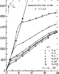
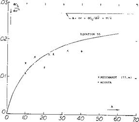
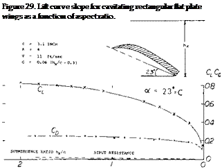
0. 6 effectiveness, while a pair of outboard flaps, cover­ing together half of the span, will only produce 0.4 times the effectiveness of a full-span flap. In other words, a cut-out in the center of a horizontal tail takes away more control effectiveness than same-size cut-offs at the lateral ends. It appears, however, that the rear lateral corners of any lifting surface have an importance for the magnitude of lift produced, which is not recognized by theory. Therefore, any deviation from rectangular flap shape, by cutting off or rounding the rear corners, is found (^,c) to reduce lift, pitching and hinge moments.

LIFT-CAVITATION-VENTILATION

The basic principles of cavitation are given in Chapter I and in “Fluid-Dynamic Drag”. As the speed is increased, cavitation will be encountered and the lift of the foil will be reduced. Thus, lift will be obtained on an airfoil in spite of cavitation. At speeds lower than cavitation would be expected, it can be shown that with proper ventilation a finite cavitation number can be simulated.

Incipient Cavitation. The critical cavitation number is that where at a particular point on the surface of a body or wing the local static pressure reduces to that of vaporization. This means that

Pnnin~ Pv “TCpmm + Pa – p^ =0 (42)

or:

c pmin = – (Pa – Pv ) q = – cra « – 195/(V, m/s) (43)

Vice versa, the incipient cavitation number is

A –Cpmin « 195/(V, m/s) and the critical speed is

Vcnt = /і95/сґа in (m/s) Vcrjt ~ 26//o7J in knots

Minimum Pressure. The minimum pressure coefficients are known for body shapes such as foil sections in particular, and thus the critical speed where cavitation can be expected can be found in equations 44 and 45. In “Fluid-Dynamic Drag”, CPrT!!n for zero lift, as well as for optimum camber, are given as a function of the lift coefficient. Both of these functions are quoted in the “compressibility” chapter.

Cpmin =-2.1 (t/2x)@CL=0 (46)

where x = location of the maximum thickness (for example at 40% of the chord). Also for properly cambered sections:

^ Cpmin – К CLOpt (47)

where К between 0.75 (for thickness locations near 30% of the chord) and 0.85 (for locations around 50% of the chord). Adding the two components the minimum

pressure at the upper side of foil sections or hydrofoils is obtained at and around their design lift coefficient. As an example, the 4412 section is shown in figure 25, both tested for pressure distribution in a wind tunnel (29,a) and for incipient cavitation in a water tunnel (30,d). At lift coefficients, at least between 0.2 and 0.6, complete agreement is found. This means that cavitation readily starts when the minimum pressure reduces to the level of the vapor pressure. In a water tunnel cavitation is achieved either by increasing the speed (the q in Cpmm) or by reducing the pressure within the tunnel as a whole (the p in <r). " 3

Pressure Peaks. There is a mathematical relationship not only between the minimum pressure coefficient of any foil section, but also between the critical Mach number (in air) and the critical cavitation number and/or the critical speed (in water). Both these critical speeds can be exceeded, however, without any loss of lift, when the minimum pressure appears only in a more or less narrow peak. Since the reasons and extent of these transgressions are different, it is not possible in the presence of peaks to make correct predictions in regard to cavitation, neither on a theoretical basis nor from experimental evidence in air. As shown in “Fluid-Dynamic Drag” the delay as found around the leading edges of foil sections seems to correspond to

= – 0.08 Cpmin (48)

An example is shown in figure 26. Within a “bucket” similar to that as found in laminar-type airfoil sections, the cavitation number (indicating the onset of cavitation) agrees with the minimum pressure coefficient found as the sum of equations 46 and 47. Outside the bucket the cavitation number increases at a rather high rate. This means that cavitation starts at a much lower speed. If, for example, Of = 2 (at the upper side of a foil section, at CL = 0.9) instead of of = 0.5 (at CL around 0.4) then the critical speed in open water will be reduced in accordance with equation 45 roughly from 40 to /0.5/2 40 = 20 knots.

LIFT-CAVITATION-VENTILATION

Pressure distribution test

(a) On 4412 Section, NACA TR 563 1936.

LIFT-CAVITATION-VENTILATION

Figure 28. Fiat plate of aspect ratio of 3.12 tested in a water tunnel (33,a).


LIFT-CAVITATION-VENTILATION

Подпись:Подпись: NON CAVITATIN^ Подпись: PRESSURE-SIDE SEPARATIONПодпись: •ч-Подпись:LIFT-CAVITATION-VENTILATIONПодпись: 60е CXПодпись:Подпись: 40

Cavitation Number Fffect. At cavitation numbers above zero it was shown (32,e) that the normal force coefficient is increased by aCn = cr. Evaluation of the data of (33,a) indicates that

CL = .8 cr (56)

Based on this analysis it would appear as in the case of small aspect ratio wing, Chapter XVII, that the flow about the edges is of importance.

Supercavitation. Since cavitation is no longer avoidable in conventional foil sections at the higher speeds, the idea was conceived to accept cavitation at the upper side and to make the best of it by forming the lower side properly. Figure 30 presents one such supercavitation section. In­creased drag, a shortcoming of such sections is the fact that in a hydrofoil boat, for example, the flow pattern has necessarily to go through a transition from fully attached or fully separated to fully cavitated. Another disadvantage is found in the fact that drag can take place within certain boundaries of the lift coefficient. Even in marine propellers where cavitation is a well-known plaque, no supercavitating designs seem to be in practical operation some ten years after their invention.

1.0

OB

06

. /

102

/

/ ^

(32) Supercavitating Hydrofoils Theory:

(a) Acosta, Three-Dimensional Supercavitating Hydro­foils, Ca. Inst of Technology to ONR 1974.

(b) Nishujama, Theory Hydrofoils Finite Span, ZAMM Vol 50, 1970.

(c) Acosta, Hydrofoils and Hydrofoil Craft Annual Review Fluid Mechanics, Vol 5 1973.

(d) Hough, J. Ship Res. 13:53-60 (1969)

(e) Betz, Influence of Cavitation Upon Ship Propellers, Proc. 3rd International Congress, Mechanics Stockholm 1930 Vol. 1 page 411.

(33) Finite Hydrofoil Wings

(a) Reichardt, Rectangular Wings with Cavitation, Max – Planck-Institute for Stomungsforscheing Gutlingen 1967.