Category Introduction to Structural Dynamics and Aeroelasticity

Calculation of Forced Response

The formulation of initial-value problems for beams in torsion is almost identical to that for strings, presented in Section 3.1.7. We first should determine the virtual work done by the applied loads, such as a distributed twisting moment per unit length discussed in Section 2.3.1. From this, we may find the generalized forces associated with torsion. Once the generalized forces are known, we may solve the generalized equations of motion, which are of the form in Eq. (3.90). The resulting initial-value problem then can be solved by invoking orthogonality to obtain values

Подпись: 1 lПодпись: 02Подпись:Подпись: 1 (Подпись: xCalculation of Forced Response

Calculation of Forced Response Подпись: 01 Calculation of Forced Response

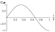
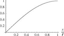
Figure 3.24. First three mode shapes for clamped-spring- restrained beam in torsion, Z = 1

of the arbitrary constants in the general and particular solutions, as illustrated in the examples in Section 3.1.7.

3.3 Uniform Beam Bending Dynamics

The free vibration of a beam in bending is often referred to as “transverse vibration.” This type of motion differs from the transverse dynamics of strings and the torsional dynamics of beams in that the governing equations of motion are of a different mathematical form. Although these equations are different, their solutions are ob­tained in a similar manner and exhibit similar physical characteristics. Again, we start with the properties varying with x and specialize when we must. Observe that whereas most aerospace structures experience combined or simultaneous bending and torsional dynamic behavior, we have here chosen certain configuration variables to uncouple these types of motion.

Example Solutions for Mode Shapes and Frequencies

In this section, we consider several examples of the calculation of natural frequen­cies and mode shapes of vibrating beams in torsion. We begin with the clamped-free
$ = 0

Figure 3.17. Schematic of clamped-free beam undergoing torsion case, often referred to as “cantilevered.” Next, we consider the free-free case, illus­trating the concept of the rigid-body mode. Finally, we consider a case that requires numerical solution of the transcendental characteristic equation: a beam clamped at its root and restrained with a rotational spring at the tip.

Example Solution for Clamped-Free Beam. To illustrate the application of these boundary conditions, consider the case of a uniform beam that is clamped at x = 0 and free at x = l, as shown in Fig. 3.17. The boundary conditions for this case are

X(0) = X'(l) = 0 (3.165)

Recall that the general solution was previously determined as

в(x, t) = X(x)Y(t) (3.166)

where Xand Y are given in Eqs. (3.138). For a = 0, the first of those equations has the solution

X(x) = Asin(a x) + B cos(a x) (3.167)

Подпись: (3.168)It is apparent that the boundary conditions lead to the following X(0) = 0 requires B = 0 X'(l) = 0 requires Aa cos(al) = 0

If A = 0, a trivial solution is obtained, such that the deflection is identically zero. Because a = 0, a nontrivial solution requires that

Подпись: (3.169)cos(al) = 0

This is called the “characteristic equation,” the solutions of which consist of a denu – merably infinite set called the “eigenvalues” and are given by

ai l = (2i -1)n (i = 1, 2,…) (3.170)

The Y(t) portion of the general solution is observed to have the form of simple harmonic motion, as indicated in Eq. (3.160), so that the natural frequency is

Подпись: GJ p Ip

Подпись: 0( Подпись: -^p-x

(3.171)

Подпись: 02 (X

Подпись: 03 (X Подпись: ФЛX
Example Solutions for Mode Shapes and Frequencies

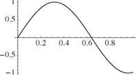
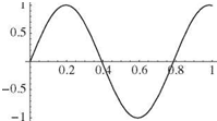
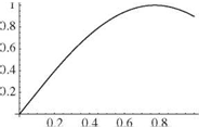
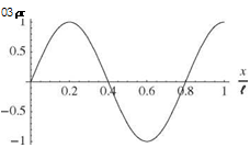
Figure 3.18. First three mode shapes for clamped-free beam vibrating in torsion

Подпись: GJ p Ip Подпись: (2i - 1)n [GJ 2 JTp Подпись: (3.172)

Because a can have only specific values, the frequencies also take on specific numer­ical values given by

Example Solutions for Mode Shapes and Frequencies Подпись: (3.173)

These are the natural frequencies of the beam. Associated with each frequency is a “mode shape” as determined from the x-dependent portion of the general solution. The mode shapes (or eigenfunctions) can be written as

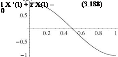
or any constant times фі (x). The first three of these mode shapes are plotted in Fig. 3.18. The zero derivative at the free end is indicative of the vanishing twisting moment at the free end.

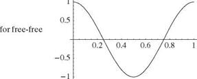
Example Solution for Free-Free Beam. A second example, which exhibits both elastic motion as described previously and motion as a rigid body, is the case of a

Example Solutions for Mode Shapes and Frequencies

Example Solutions for Mode Shapes and Frequencies

ai t = i n (i = 1, 2,…)


(3.178)


and the corresponding natural frequencies become


i n GJ

1 Wp


(3.179)


The associated mode shapes are determined from the corresponding X(x) as


Фі (x) = cos(a;x) = cos t


(3.180)


These frequencies and mode shapes describe the normal mode of vibration for the elastic degrees of freedom of the free-free beam in torsion.

Now, if in the previous analysis the separation constant, a, is taken as zero, then the governing ordinary differential equations are changed to


Xl = РІ£Ї = 0

X GJY or


(3.181)


Example Solutions for Mode Shapes and Frequencies

(3.182)


(3.183)


The arbitrary constants, a and b, in the spatially dependent portion of the solution again can be determined from the boundary conditions. For the present case of the


free-free beam, the conditions are

Подпись: (3.184)X'(0) = 0 requires a = 0 X'(t) = 0 requires a = 0

Because both conditions are satisfied without imposing any restrictions on the con­stant b, this constant can be anything, which implies that the torsional deflection can be nontrivial for a = 0. From X(x) with a = 0, it is apparent that the corresponding value of в is independent of the coordinate x. This means that this motion for a = 0 is a “rigid-body” rotation of the beam.

The time-dependent solution for this motion, Y(t), also is different from that obtained for the elastic motion. Primarily, the motion is not oscillatory; thus, the rigid-body natural frequency is zero. The arbitrary constants, c and d, can be ob­tained from the initial values of the rigid-body orientation and angular velocity. To summarize the complete solution for the free-free beam in torsion, a set of general­ized coordinates can be defined by

в(x, t) = ^2 Фі(x)&(t) (3.185)

і =0

where

Подпись: / і п x Фі = cos I — Подпись: (i = 1, 2,...) Подпись: (3.186)

Ф0 = 1

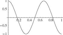
The first three elastic mode shapes are plotted in Fig. 3.20. The zero derivative at both ends is indicative of the vanishing twisting moment there. The natural frequencies associated with these mode shapes are

Подпись: і п IGJ nWp Подпись: (і = 1, 2,...) Подпись: (3.187)

«0 = 0

Note that the rigid-body generalized coordinate, f0(t), represents the radian measure of the rigid-body rotation of the beam about the x axis.

A quick way to verify the existence of a rigid-body mode is to substitute « = 0 and X = a constant into the differential equation, and boundary conditions for X. A rigid-body mode exists if and only if all are satisfied. Caution: Do not try to argue that there is a rigid-body mode because a = 0 satisfies the characteristic equation, Eq. (3.177). To obtain that equation, we presupposed that a = 0!

Example Solution for Clamped-Spring-Restrained Beam. A final example for beam torsion is given by the system shown in Fig. 3.21. The beam is clamped at the root (x = 0) end, and the other end is restrained with a rotational spring having spring constant к = ZGJjt, where Z is a dimensionless parameter. The boundary

Подпись: x 1
Example Solutions for Mode Shapes and Frequencies

Подпись: ФЛx)Подпись: x 7 Example Solutions for Mode Shapes and Frequencies

Подпись: X(0) = 0 GlX'(l) = -kX(l) Подпись: G z x(i) Example Solutions for Mode Shapes and Frequencies Подпись: x 7
Подпись: Figure 3.20. First three elastic mode shapes beam vibrating in torsion

conditions on X are thus

When these boundary conditions are substituted into the general solution found in Eqs. (3.138), we see that the first condition requires that B = 0; the second condition, along with the requirement for a nontrivial solution, leads to

Подпись:Z tan(al) + al = 0

Подпись: < Є
Example Solutions for Mode Shapes and Frequencies

Figure 3.21. Schematic of torsion problem with spring

af

, tan(a^)

Example Solutions for Mode Shapes and Frequencies

z

This transcendental equation has a denumerably infinite set of roots that cannot be found in closed form. However, as many of these roots as desired can be found using numerical procedures found in commercially available software packages such as Mathematical Maple™ and MATLAB™

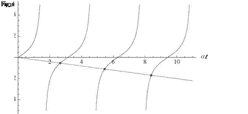
To facilitate this sort of root-finding in general, we may need to specify initial guesses for the values of ai. These can be found using graphical means by plotting, for example, tan(ai) and – ai/Z versus ai for a specified value of Z = 5, as shown in Fig. 3.22. The points where these curves intersect (indicated by dots in the figure) are the solutions, the locations of which are seen to be approximately at ai = 2.6, 5.4, and 8.4. These values, when used as initial guesses in a root-finding application, provide quick convergence to a1i = 2.65366, a2i = 5.45435, and a3i = 8.39135. As an alternative approach for this particular example, we may solve Eq. 3.189 for Z and plot it versus ai to find the roots without iteration.

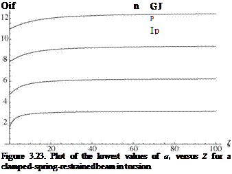
Thus, the roots of Eq. (3.189) are functions of Z, and the first four such roots are plotted versus Z in Fig. 3.23. Denoting these roots by ai, with i = 1, 2,…, we obtain the corresponding natural frequencies

Vi = ai (i = 1,2,…) (3.190)

P Ip

From the plots (and from Eq. 3.189), we note that as Z tends toward zero, a1i tends toward n/2, which means that the fundamental natural frequency is

Подпись: (Z ^ 0)Example Solutions for Mode Shapes and Frequencies(3.191)

which is the natural frequency of a clamped-free beam in torsion (as shown herein). We also can show that as Z tends to infinity, a1i tends toward n so that the

Example Solutions for Mode Shapes and Frequencies Подпись: (3.192)

fundamental natural frequency is

which is the natural frequency of a clamped-clamped beam in torsion. Recalling the similarity of the governing equations and boundary conditions, the determination of the natural frequencies of a clamped-clamped beam in torsion follows directly from the previous solution for natural frequencies of a string fixed at both ends.

To obtain the corresponding mode shapes, we take the solutions for ai and substitute back into X, recalling that we can arbitrarily set A = 1 and that B = 0. The resulting mode shape is

фі = sin(a^x) (i = 1,2,…) (3.193)

The first three modes for Z = 1 are shown in Fig. 3.24. As expected, neither the twist angle nor its derivative are equal to zero at the tip. Close examination of Fig. 3.24 illustrates that for higher and higher frequencies, the spring-restrained ends behave more and more like free ends.

Boundary Conditions

For a beam undergoing pure torsion, one boundary condition is required at each end. Mathematically, boundary conditions may affect 0 as well as its partial derivatives, such as д0/dx and d20/dt2, at the ends of the beam. In the context of the separation of variables, these conditions lead to corresponding conditions on X and/or X’ at the ends. These relationships are necessary and sufficient for determination of the constants A and B to within a multiplicative constant.

The nature of the boundary condition at an end stems from how that end is restrained. When an end cross section is unrestrained, the tractions on it are identi­cally zero. Conversely, the most stringent condition is a perfect clamp, which allows no rotation of an end cross section. Although this is a common idealization, it is practically impossible to achieve in practice.

Cases that only partially restrain an end cross section involve elastic and/or inertial reactions. For example, an aircraft wing attached to a flexible support, such as a fuselage, is not a perfect clamped condition; the root of the wing experiences some rotation because of inherent flexibility at the point of attachment. A boundary condition that is idealized in terms of a rotational spring may be used to create a more realistic model for the support flexibility. Appropriate values for support flexibility can be estimated from static tests. Boundary conditions involving inertial reactions may stem from attached rigid bodies to model the effects of fuel tanks, engines, armaments, and so on.

Figure 3.10. Clamped end of a beam

Boundary ConditionsIn this section, we consider two boundary conditions of the “primitive” type and two examples of derived boundary conditions that can be imposed at the ends of the beam to determine the constants A and B.

Clamped End. In this first primitive case (Fig. 3.10), the x = £ end of the beam is assumed to be clamped or rigidly attached to an immovable support. As a conse­quence, there is no rotation due to elastic twist at this end of the beam, and the boundary condition is

Подпись: (3.139) (3.140) в(£, t) = 0 = X(£)Y(t) which is identically satisfied when

X(£) = 0

Free End. For the second primitive case, we consider the x = £ end cross section of the beam to be free of stress (Fig. 3.11). Therefore, the twisting moment resultant on the end cross section must be zero

T(£, t) = GJ(£) — (£, t) = 0 (3.141)

d x

Because GJ(£) > 0, this specializes to

дв

(£, t) = X'(£)Y(t) = 0 (3.142)

д X

Thus, the specific condition to be satisfied is

X'(£) = 0 (3.143)

Подпись: Figure 3.11. Free end of a beam
Boundary Conditions

Other Forms of End Restraint. In any cross section of a beam undergoing deforma­tion, there is a set of tractions on the plane of a typical cross section; a traction is a projection of the stress (three-dimensional) onto a surface (two-dimensional). From tractions at a given cross section, we can define the resultant force and moment at that station of the beam. When the end of a beam is connected to a rigid body, the

Boundary Conditions Boundary Conditions Подпись: X
Подпись: Figure 3.12. Schematic of the x = l end of the beam, showing the twisting moment T, and the equal and opposite torque acting on the rigid body
Подпись: Beam

body exerts forces and moments on the beam that are balanced by the distributed traction on the end cross section. That is, the force and moment resultants on the end cross section are reacted by equal and opposite forces and moments on the rigid body. These facts, along with application of suitable laws of motion for the attached body, allow us to determine the boundary conditions.

In the case of torsion, for any cross section, the resultant moment about x of tractions caused by transverse shearing stress has the sense of a twisting moment, T, given by

__ dQ

T = GJ — (3.144)

dx v ’

With x directed to the right and the outward-directed normal along the positive x direction at the end of the beam where x = l, a positive twisting moment is directed along x in the right-handed sense. To avoid coupling with transverse motion, we stipulate that the mass center C of the attached rigid body lies on the x axis (i. e., the elastic axis of the beam). The body has a mass moment of inertia IC about C so that it contributes a concentrated rotational inertia effect on the beam. The free-body diagram for the problem is then as shown in Fig. 3.12. By Newton’s third law, the beam’s twisting moment produces an equal and opposite torque on the rigid body.

Recall that Euler’s second law for a rigid body is stated precisely in Section 2.1.2. The only forces acting on the rigid body here3 are the contact forces from the beam. So, the x component of the left-hand side of Euler’s law is the sum of all moments acting on the body; that is

(EM)x = – T(l, t) (3.145)

Boundary Conditions Подпись: x Подпись: д2в, N IC (l t) Подпись: (3.146)

where the sign in front of T is negative because of the free-body diagram and the sign convention, which has moments acting on the body as positive in the same direction as the rotation of the body—along x in the right-handed sense. The x component of the right-hand side is the inertial time derivative of the inertial angular momentum about C, here simply the moment of inertia times the angular acceleration:

where the left superscript on the left-hand side reflects the fact that the time deriva­tive is taken in the inertial frame F, defined in Section 2.1.2. Euler’s law for this rigid

Подпись: 3Recall that we normally ignore gravity for free-vibration problems.

Boundary Conditions
Подпись: Figure 3.13. Schematic of the x = 0 end of the beam, showing the twisting moment T, and the equal and opposite torque acting on the rigid body
Подпись: Beam

This equation then expresses the boundary condition of a beam undergoing uncou­pled torsional vibration with a rigid body attached at x = l.

When the body is attached to the x = 0 end, there is a subtle but important difference. With x directed to the right and the outward-directed normal along the negative x direction at the x = 0 end of the beam, a positive twisting moment is directed along – x in the right-handed sense. The free-body diagram for the problem is then as shown in Fig. 3.13. By Newton’s third law, the twisting moment produces an equal and opposite torque on the rigid body, which is in the direction of a positive rotation for the body. Therefore, Euler’s law (and the resulting boundary condition) is written as

d 2В

T(0, t) = Ic(0, t) (3.149)

or

__ dQ d2$

GJ — (0, t) = Ic^(0, t) (3.150)

Thus, this equation expresses the boundary condition of a beam undergoing uncou­pled torsional vibration with a rigid body attached at x = 0.

The following example illustrates a convenient way to think about the contri­bution of a spring to the boundary of a beam undergoing only torsional rotation. Consider a beam with an attached rigid body at its x = l end, such that the rigid body is, in turn, restrained by a light torsional spring attached to the ground. The rotational sign convention does not change; В is always positive in the x direction (i. e., to the right in the sense of the right-hand rule). The rigid body, because it is attached to the end of the beam, rotates by В (l, t). Thus, the rotational spring reacts against that rotation, and the moment applied by the spring to the body is opposite to the direction of the rotation (Fig. 3.14). The boundary condition for the beam results from applying Euler’s second law to the rigid body, so that

d 2q

-кВ(l, t) – T(l, t) = Ic —7(1, t) (3.151)

d t2

If the body-spring mechanism is instead on the x = 0 end of the beam, then the moment exerted by the spring is still in the same direction. However, what constitutes a positive twisting moment on the beam has the opposite sense, and the boundary condition changes to

d 2в

-кв(0, t) + T(0, t) = Ic(0’t) (3.152)

Clearly, if the body is absent, one may set Ic = 0. Then, the problem reduces to the elastically restrained boundary condition, as shown in Fig. 3.15. The twisting moment at the beam end must be equal and opposite to the spring reaction for any finite rotation due to twist at the x = l end, so that

__ дв

-T(l, t) = – GJ—(l, t) = кв(l, t) (3.153)

д X

At the x = 0 end, however

Подпись: (3.154)

Boundary Conditions
Подпись: Figure 3.14. Example with rigid body and spring
Подпись: X

___ дв

T(0, t) = GJ—(0, t) = кв (0, t)

д X

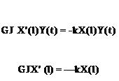
Подпись: which requires that Подпись: GJ X'(l)Y(t) = -kX(l)Y(t) GJX' (l) = —kX(l) Подпись: (3.155) (3.156)

To be useful for separation of variables, we must determine the corresponding boundary condition on X. Thus, we write в(x, t) as X(x)Y(t) as before, yielding

Readers should verify that the same type of boundary condition at the other end would yield

GJX’ (0) = kX(0) (3.157)

where the sign change comes about by virtue of the switch in the direction noted previously for a positive twisting moment.

Подпись: Л ЧІЧЧЧЧЧЧЧ Figure 3.15. Elastically restrained end of a beam

Figure 3.16. Inertially restrained end of a beam

Boundary ConditionsConversely, if the spring is absent, we may set к = 0, and the problem reduces to the inertially restrained case with only a rigid body attached to the x = l end (Fig. 3.16). The twisting moment at the beam end must be equal and opposite to the inertial reaction of the concentrated inertia for any finite angular acceleration of the end. Therefore

__ dQ d2$

-GJ—(l, t) = Ic^(£, t) (3.158)

Expressing this condition in terms of X(x), Y(t), and their derivatives, we find that

-GJX'(l)Y(t) = IcX(t)Y(t) (3.159)

Boundary Conditions Подпись: (3.160)

From separation of variables, it was determined from the second of Eqs. (3.137) that for free vibration (i. e., no external forces), we may regard Y(t) as describing simple harmonic motion; that is

Substitution into the preceding condition then yields

Подпись: (3.161)__ GJ

GlX'(l)Y(t) = a2 IcX(l)Y(t)

P Ip

which requires that

p IpX'(l) = a2 IcX(I) (3.162)

As before, readers should verify that the same type of boundary condition at the other end would yield

p IpX'(0) = – a2 IcX(0) (3.163)

It is appropriate to note that the use of Eq. (3.160) allows us to express Eq. (3.158) as

__ dQ

GJ—(l, t) = Ш2IcQ(l, t) (3.164)

д X

with the caveat that this condition holds true only for simple harmonic motion.

Example Calculations of Forced Response

In this section, we present two examples of forced-response calculations. These examples also appropriately are called “initial-value problems.” The first has zero initial displacement and velocity; the second has nonzero initial displacement and zero initial velocity.

Example: Calculation of Forced Response. An example of a dynamically loaded uniform string is considered to illustrate the generalized force computation and subsequent solution for the string displacement. The specific example is a uniformly distributed load (in space) of simple harmonic amplitude (in time) shown in Fig. 3.8 with

The generalized force can be determined from the integral of a distributed loading as

rl

/ f (x, t)фі (x)dx Jo

Подпись: фі (x)dxПодпись: = ^01(t )ФіПодпись: 1 2 Example Calculations of Forced Response(3.119)

= F01(t )sin

Example Calculations of Forced Response

because

These integrals can be evaluated easily by noting the orthogonality property of the sine functions. The result gives the following values for the constants Bi:

B4 = h

Bi = 0 (i even but = 4) (3.125)

Bi = – Ci (i odd)

The initial velocity being zero requires that

(x, 0) = £ h (0)Фі (x) = J2 Vi A sin = 0 (3.126)

Multiplication by sin( jnx/l)dx and integration results in determining that Ai = 0 for all i. These results can be summarized by noting that h = 0 for all even values of i except

h4 = h cos (v4t)

(3.127)

and for odd i

hi = Ci [1 – cos (ю-t)] (i odd)

(3.128)

The constants Ci can be determined by substitution of the odd generalized coordinates back into the equations of motion

MiCi= F0(-1)^ t > 0

(3.129)

Given that Mi = mt/2, this yields

C 2Щ(-1) ¥ Ci T(i n )2

(3.130)

so that the complete string displacement becomes

v(x, t) = jn hi (t)Фі (x)

i =1

і / ■ /4nx 21F0 ^ (-1)1-1 /inx

= h cos (a>4t) sin ^ — j + ТПЇ Z_, — -2 [1 – cos M)] sin ^ — j

(3.131)

Thus, the first term is the response due to initial displacement, and the sum over the odd-indexed modes is the response due to the forcing function.

3.2 Uniform Beam Torsional Dynamics

Although vibrating strings are easy to visualize and exhibit many of the features of vibrating aerospace structures, to analyze such structures, more realistic models are needed. In this section, we apply the concepts related to the modal representation
to the dynamics of beams in torsion. A beam is a structural member in which one dimension is much larger than the other two. It is thus understandable to idealize the twisting and bending of high-aspect-ratio wings and helicopter rotor blades in terms of beam theory, especially in conceptual and preliminary design. Because many behavioral characteristics of typical aeronautical structures are found in beams, the torsion of beam-like lifting surfaces plays a vital role in both static and dynamic aeroelasticity.

3.2.1 Equations of Motion

Подпись: d д X Example Calculations of Forced Response Example Calculations of Forced Response Подпись: (3.132)

For free vibration of a beam in torsion, we specialize the equation of motion derived in Section 2.3.1 by setting r (x, t) = 0 to obtain

Other than the quantities that multiply the partial derivatives, this equation of motion is similar to that for the dynamic behavior of a string. The difference is that the stiffness coefficient GJ (x), unlike the tension in the string, may not be constant. Specialization to the spanwise uniform case is undertaken to obtain a closed-form solution. Properties varying with x are not an obstacle for application of the variety of approximate methods discussed in Section 3.5, but here we are concerned with obtaining closed-form solutions to aid in understanding the results. As shown when we explore the boundary conditions in detail, there are more interesting possibilities for the boundary conditions for beams in torsion than there are for the string.

As before, we apply separation of variables, by substituting

Подпись: (3.133)в(x, t) = X(x)Y(t)

into the partial differential equation of motion and arranging the terms so that dependencies on x and t are separated across the equality. This yields

Подпись: (3.134)Подпись: (3.135)Подпись:[GJ( x) X 7(x)]7 = Y(0 P Ip(x)X(x) Y(t)

Thus, each side must equal a constant—say, – a>2—so that

[J x) X7 (x)]7 = Щ= _ш2 P Ip(x) X(x) Y(t)

Two ordinary differential equations then follow; namely

[GJ (x) X’ (x)]7 + p Ip(x)a>2 X(x) = 0 Y(t) + a>2Y(t) = 0

The first of Eqs. (3.136) has variable coefficients in x and—except for certain special cases such as spanwise uniformity—does not possess a closed-form solution. The second, however, is the same as the second of Eqs. (3.6), the solution of which is well known.

Some specialization is necessary in order to proceed further. Therefore, we consider only beams with spanwise uniform properties. Eqs. (3.136) then become

Подпись: (3.137)Подпись: (3.138)X" + a2 X = 0 Y + ш2У = 0

where a2 = pIpu>2/GJ. For a = 0, the solutions can be written as

X(x) = Asin(ax) + B cos(a x) Y(t) = C sin (a>t) + D cos (&t)

To complete the solutions, constants A and B can be determined to within a mul­tiplicative constant from the boundary conditions at the ends of the beam; C and D can be found as a function of the initial beam deflection and rate of deflection. Because the partial differential equations of motion governing both transverse vibra­tion of uniform strings and torsional vibration of uniform beams are one-dimensional wave equations, we rightfully can expect all of the previously discussed properties of standing and traveling waves to exist here as well.

Note that the special case of a = 0 is an important special case with a different set of general solutions. It is addressed in more detail in Section 3.2.3.

Generalized Force

The generalized force, Ei (t)—which appears on the right-hand side of the general­ized equations of motion—represents the effective loading associated with all forces and moments not accounted for in P, which includes any nonconservative forces and moments. These forces and moments are most commonly identified as exter­nally applied loads, which may or may not be a function of modal response. They also include any dissipative loads such as those from dampers. To determine the contribution of distributed loads, denoted by f (x, t), the virtual work is computed from Eq. (2.38), repeated here for convenience as

Generalized Force(3.91)

The term Sv(x, t) represents a variation of the displacement field, typically re­ferred to as the “virtual displacement,” which can be written in terms of the

Figure 3.6. Concentrated force acting on string

Generalized Forcegeneralized coordinates and mode shapes as
TO

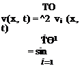
Sv(x, t) = ^2 Фі (x)S^i (t) (3.92)

i=1

where S^i (t) is an arbitrary increment in the ith generalized coordinate. Thus, the virtual work becomes

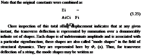
______ /. г TO

S W = f (x, t)Фі (хЩі (t)dx

Подпись: (3.93)0 i=1

TO /. г

= J2 S^i (t) f (x, t)Фі (x)dx

0

Identifying the generalized force as

Si (t) = f (x, t)Фі (x)dx (3.94)

0

we find that the virtual work reduces to

TO

SW =J2 Si (t) S^i (t) (3.95)

І =1

The loading f (x, t) in this development is a distributed load with units of force per unit length. If instead this loading is concentrated at one or more points—say, as Fc(t) with units of force acting at x = xc as shown in Fig. 3.6—then its functional representation must include the Dirac delta function, S(x – xc), which is similar to the impulse function in the time domain. In this case, the distributed load can be written as

Подпись: (3.96)f (x, t) = Fc(t)S(x – Xc)

Recall that the Dirac delta function can be thought of as the limiting case of a rectangular shape with area held constant and equal to unity as its width goes to zero (Fig. 3.7). Thus, it may be defined by its integral property; for example, for a < x0 < b

b

S(x – x0)dx = 1

Подпись: (3.97)a

b

f (x)S(x – x0)dx = f (x0)

Figure 3.7. Approaching the Dirac delta function

As a consequence, this integral expression for the generalized force can be applied to the concentrated load so that

Si (t) = Fc(t)8(x – Xc)Фі (x)dx

0

Подпись: (3.98)= Fc (t) 8(x – Xc)фі (x)dx

0

= Fc (t)фі (xc)

Generalized Equations of Motion

Once the free-vibration modes have been determined for a linear, conservative system, it is a straightforward procedure to determine the system’s response to any external loading. This is accomplished by treating each mode of vibration as a dimensional degree of freedom whose scalar coordinate is the mode’s generalized coordinate. For each of these modal degrees of freedom, a “generalized equation of motion” can be formulated from Lagrange’s equations (see the Appendix and Section 2.1.5). The generalized equations of motion for the string problem can be formulated by substituting expressions for the potential and kinetic energies into

Подпись: (i = 1, 2,...)Lagrange’s equations; see Eq. (2.14), repeated here for convenience as

d dK d P

dt dji + Wi =

In the energy expressions, the string displacement is represented in terms generalized coordinates and mode shapes as

v(x, t) = Фі (x)Hi (t)

Подпись:

Generalized Equations of Motion

і =1

For the string, the mode shapes and their first derivatives are sinusoidal functions; consequently, they form an orthogonal set.2 That is

Подпись:

Generalized Equations of Motion Подпись: (3.81)
Generalized Equations of Motion
Подпись: (3.78)
Подпись: (3.79)

f Ф’і (x)<£j(x)dx = 0 (i = j) 0

Подпись:It is not true in general that the derivatives of mode-shape functions form an orthogonal set.

Generalized Equations of Motion
The integral in this expression can be integrated by parts as

the total kinetic energy becomes

O

K = – J2 Mi 12 (3.89)

І =1

The “generalized equations of motion” now can be obtained by substitution of the kinetic energy of Eq. (3.89) and the potential energy of Eq. (3.84) into Lagrange’s

equations given as Eqs. (3.74). The resulting equations are then

Подпись: (3.90)Mi (li + vfe) = E (i = 1, 2,…)

When using a modal representation, we may use equations of this form for the dynamic analysis of any linearly elastic structure. The generalized mass and natural frequencies, of course, will differ depending on whether the structure is a string, a beam in torsion or bending, a plate or shell, or a complete aircraft. The left-hand side of this equation has at least these terms regardless of the system being analyzed. Kinetic and potential energies also may contain contributions from discrete elements such as added particles, rigid bodies, or springs. Finally, additional terms could arise from potential energy of conservative applied loads, such as gravity.

The right-hand side, conversely, is highly problem-dependent and is addressed next. The case of a vibrating structure without external forces is a special case, previously discussed in Section 3.1.3. When there are no external forces, Ei = 0 for all i. The resulting general solution of Eq. (3.90) is the same as that presented in Section 3.1.3, which was obtained without reference to the generalized equations of motion and yields results depending only on the initial conditions. When including an entity such as a spring in the potential energy, we are enlarging the boundary of the system to include a new element. However, when the same entity is included through its contribution to the generalized forces, it is being treated as a source of external forces, something external to the system. Despite this philosophical distinction, the end result is the same (see Problem 5). Any effect that can be included in the generalized equations of motion through potential energy can be included instead through the generalized force. It is extremely important to not count the same effect twice (e. g., including the same entity through both potential energy and generalized forces).

Traveling Wave Solution

In the preceding section, a modal solution was obtained for the string problem. The solution depicted the total displacement as a summation of specific shapes as measured relative to the ends of the string. Each shape had an amplitude that was, in general, a function of time. When these individual modal contributions were of constant amplitude at their modal frequency, they appeared as standing or fixed waves along the string.

Another interpretation of the string response is now considered by examining the solution obtained for a string with an initial displacement but zero initial velocity and external loading. In this case, the Eis were all zero so that the displacement was written as

v(x,1) = Esin (i?) Ficos (Vm?) (3.56)

The Fis can be determined from the initial shape, f (x), as

Fi = 1 fo f (x) sin (dX (3.57)

It also may be noted that the initial shape can be represented by

СО у ч

v(x, 0) = f (x) = J2 Pi sin ( ^ ) (3.58)

i =1 ‘ ‘

Equation (3.58) is known as the Fourier sine series representation of the function f (x). Additional information on the Fourier series may be found in more advanced textbooks on structural dynamics and applied mathematics. Now, to rewrite the general solution for this problem, the two well-known identities

Подпись: (3.59) (3.60) sin(a + в) = sin(a) cos(e) + cos(a) sin(e)

sin(a – в) = sin(a) cos(e) – cos(a) sin(e)

can be added to yield another identity as

1

sin(a) cos(e) = і [sin(a + в) + sin(a – в)]

Traveling Wave Solution Подпись: sin Подпись: i n T ' T x + m', Подпись: + sin Подпись: i n T ' T Г V m1, Подпись: (3.61)

This identity can be used to rewrite the general solution given by Eq. (3.56) as

Подпись: v(x, t) Подпись: T m Подпись: (3.62)

Equation (3.58) gives the functional form of f (x) as an infinite sum of sine func­tions with coefficients Fi. The two terms on the right-hand side of Eq. (3.61) are of the same form as the sum in Eq. (3.58) and can be identified as having the func­tional form of f (x) but with different arguments. It is therefore possible to rewrite Eq. (3.61) as

This is the principal result of the traveling-wave solution. In reality, it is mathemati­cally identical to the previously given standing-wave solution in Eq. (3.56); the only difference is point of view.

Traveling Wave Solution Traveling Wave Solution Подпись: (3.63)

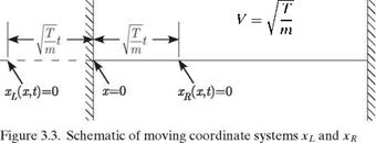
To illustrate how Eq. (3.62) represents traveling waves along the string, the two arguments of the shape function are replaced by new spatial coordinates, the origins of which are time dependent. The new coordinates are defined as

Equation (3.62) becomes

1

v(x>t) = 2 [ f (xL) + f (xR)] (3.64)

which indicates that the time-dependent string shape is the sum of two shapes of a form identical to the initial shape but of one half its magnitude. Initially, at t = 0, the origins of the xL and xR coincide with the x origin as

Подпись: (3.65)xL(x, 0) = 0 at x = 0 xR(x, 0) = 0 at x = 0

Traveling Wave Solution Подпись: (3.66)

At any later time t > 0, the origins of xL and xR can be located by

These results indicate that the xL coordinate system is moving to the left with a speed V T/m and the xR coordinate system is moving to the right with the same speed. These origin positions are indicated in Fig. 3.3. As a consequence of these moving origins, the shape f (xL)/2 appears to propagate to the left and the shape

Подпись: J,£, J-д
Traveling Wave Solution

f (xr)/2 appears to propagate to the right. Both of these shapes will move at a constant propagation speed of

so that Eq. (3.62) may be written in the form

1

v(x, t) = 2[ f (x + Vt) + f (x – Vt)] (3.68)

This is also called D’Alembert’s form of the equation.

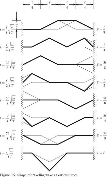
When these shapes reach one of the walls, the deflection must go to zero to satisfy the boundary conditions. This condition at each wall causes the shapes to be reflected in the opposite direction. These reflections appear as inverted shapes propagating away from the walls, again with the speed V = V T/m. This reflected-wave behavior is inherent to the Fourier sine series representation of f (x) given in Eq. (3.58). Determination of the string displacement at times subsequent to t = 0 requires the evaluation of f (x ± Vt) in Eq. (3.62). Although the function f (x) is defined only for the range 0 < x < £, the arguments x + Vt and x – Vt significantly exceed this range. The Fourier sine series for f(x), Eq. (3.58), possesses two distinct mathematical properties that permit evaluation of the function throughout the extended range of the argument and demonstrate the reflected-wave behavior.

First Property of f (x). Because all terms in the Fourier sine series for f (x) are odd functions of x, f (x) must also be an odd function. This property can be described as

f (-x) = ~f (x) (3.69)

It is immediately seen that this is a description of the reflected-wave behavior at the x = 0 wall.

Second Property of f (x). Because all terms in the Fourier sine series for f(x) are periodic in x with a period of 2£, then f (x) also must be periodic in x with a period of 2£. This property can be described as

f (x) = f (x + 2n£) for n = 0, ±1, ±2,… (3.70)

This relationship, in conjunction with the previously noted “odd” functionality of f (x), describes the reflected-wave behavior at the x = £ wall.

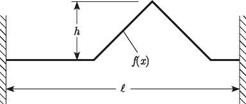
Figure 3.4. Example initial shape of wave

Traveling Wave SolutionGeneral Evaluation of f (x ± Vt). These two properties can be applied simulta­neously for the evaluation of f (x + Vt) and f (x – Vt) for any value of their argument—say, x ± Vt. When this argument lies within the range

nt < x ± Vt < (n + 1)t (3.71)

where

Подпись: (3.72)Traveling Wave Solution
n = 0, ±1, ±2,

Подпись: f(x ± Vt) = (-1)nf j(-1)n Traveling Wave Solution Подпись: (3.73)

then

We used Eq. (3.70) to reduce the range of motion, which wasinitially-to < x < +to, down to the range 0 < x < t, our physical space (i. e., where the string actually is mounted).

Example of Traveling Wave. The initial string shape is given in Fig. 3.4. At subse­quent times, the string shape appears as shown in Fig. 3.5. The absolute distance each of the half shapes has traveled at time t is denoted by x. The faint lines are the displacements associated with the two constituent waves after transformation to bring them into the range 0 < x < t, and the bold line is the sum of these two displacements. The displacement during the time t^/mfT < t < 2L/mfT is a mirror image of the progression revealed in Fig. 3.5 with a return to the original shape at t = 2tVm/ T. The motion is periodic thereafter with period 2L/mfT.

Using Orthogonality

The property of orthogonality is useful in many aspects of structural-dynamics anal­ysis. As an illustration, consider the response of an unforced uniform string to initial conditions. In this case, there are no external loads on the string, but it is presumed to have an initial deflection shape and an initial velocity distribution. Let these initial conditions be represented as

v(x, 0) = f(x) dv

dfi (x’ 0) = g(x)

where both f (x) and g(x) must be compatible with the boundary conditions.

Подпись: v(x, 0) dv m(x 0) Using Orthogonality Подпись: (3.45)

Using Eq. (3.21), these initial conditions can be written in terms of the modal representation as

Подпись: dx

Both of these relationships are multiplied by sin (jnx/l) dx and integrated over the length of the string. The first relationship yields

Подпись: = FjUsing Orthogonality(3.46)

Fjl

2

Подпись: (3.47)
Using Orthogonality
Using Orthogonality

where the evaluation used the orthogonality property of the mode shapes, which causes every term in the infinite sum to be zero except where i = j. The mass per unit length is constant for this case and hence does not appear under the integral. The second relationship can be reduced in a similar manner, so that

Ejj n T

2 V m

This treatment of the initial conditions therefore permits a direct evaluation of the unknown constants (Ei and Fi) in the modal representation of the total string displacement; that is

Using Orthogonality(3.48)

Thus, for the prescribed initial conditions given by f (x) and g(x), the resulting string displacement can be described as

TO

Подпись: [Ei sin(«;t) + Fi cos(«;t)]Подпись: (3.49)v(x, t) = ^2 sin

i =1

Using Orthogonality

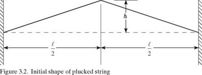
Example: Response Due to Given Initial Shape. To further illustrate this proce­dure, consider the case of the plucked string with zero initial velocity. Let the initial shape be as shown in Fig. 3.2. If we assume the initial velocity to be zero, then g(x) = 0 and Ei = 0 for all i. The string displacement becomes

Using Orthogonality Подпись: (3.51)

v(x, t) = F. sin l-^ cos(«ii) (3.50)

Using Orthogonality Подпись: (3.52)

Substitution of this function into the preceding integral yields

Подпись: Fi = Using Orthogonality Подпись: (i odd) (i even) Подпись: (3.53)

It may be noted that sin(i n/2) is zero for all even values of the index and that it is either +1 or -1 for odd values. If desired, these constants can be written as

The fact that F. = 0 for all even values of i is indicative of the symmetry of the initial string displacement about the midpoint. That is, because the initial shape is symmetric about x = i/2, no antisymmetric modes of vibration are thereby excited. The total string displacement becomes

8h (-1)L-r, (iжx

v(x, t) = —2 T2—sin i cos(«;t) (3.54)

n i=1,3,… i Vі/

where

Подпись: (3.55)i ж T і m

It should be noted from this solution that the modal contributions to the total displacement significantly decrease as the mode number (i. e., the index i) increases. This can be observed by the dependence of Fi on i and is characteristic of almost all structural-dynamics response problems; thus, it permits a truncation of the infinite sum to a finite number of the lower-order modes. This solution indicates that the string will vibrate forever, with the string periodically returning to its initial shape. In actual systems, however, there are always dissipative phenomena that cause the motion to die out in time. This is considered when we address aeroelastic flutter in Chapter 5.

Orthogonality of Mode Shapes

A most significant property of the mode shapes derived for the string is that they form a set of orthogonal mathematical functions. If the mass distribution is nonuniform along x, then the mode shapes are no longer sin(i nx/t); instead, they must be found by solving the first of Eqs. (3.6). The resulting mode shapes, however, may not be expressible in closed form. Nonetheless, they are orthogonal but with respect to the mass distribution as a weighting function. In such a case, this condition of functional orthogonality can be described analytically as

ft

/ т(х)фі (х)фj (x) dx = 0 (i = j) h (3.28)

= 0 (i = j)

To prove that the mode shapes obtained for the string problem are orthogonal, an individual modal contribution given by

Подпись: (3.29)Vi (x, t) = фі (x)%i (t)

where фі(x) is a normalized solution of the first of Eqs. (3.6). Substituting vi(x, t) into the governing differential equation (i. e., wave equation), we obtain

Подпись: (3.30)d 2 Vi d 2 Vi

T dx2 = m d t2

For example, with SI units, one has the units of T as N, m as kg/m, and t as m. With English units, one has the units of T as lb, m as slugs/ft, and t as ft.

or


Подпись: (3.31)Тф’/(х)& (t) = т(х)фі (x)h (t)

Because the general (i. e., homogeneous) solution for the generalized coordinate is a simple harmonic function, then we may write

Подпись: (3.32) (3.33) (3.34) ft = —2 ft

Thus, the wave equation becomes

ТФШі (t) = ~т(х)фі (х)о2& (t)

so that

Тф-(х) = —т(х)фі (х)о2

If this procedure is repeated by substituting the jth modal contribution into the wave equation, a similar result

Подпись: (3.35)Тф’-(х) = —т(х)ф j (х)а>2

is obtained. After multiplying Eq. (3.34) by ф j and Eq. (3.35) by фі, subtracting, and integrating the result over the length of the string, we obtain

fe fe

(o2 — a>2) J т(х)фі (х)фj(х)йх = TJ [фі (х)ф’-(х) — ф"(х)фj(х)] йх (3.36)

Orthogonality of Mode Shapes Подпись: (3.37)

The integral on the right-hand side can be integrated by parts using

Подпись: for the first term and Подпись: aa u = фі X 43 II s 43 v = Ф] dv = ф'-йх u = ф j X 43^ 3=7 II s 43 v = ф'і dv = ф"йх Orthogonality of Mode Shapes

by letting

for the second. The result becomes

(o2 — a)2) т(х)фі (х)ф j (х)йх

Подпись: (3.40)Jo

= T {фіф] — ф[фj) |0 — ^ (ф[ф] — ф[ф])йх = 0

Every term on the right-hand side is zero: the first and second because the mode shape is zero at both ends by virtue of the boundary conditions given by Eqs. (2.27),
and the integral because of cancellation. It may now be concluded that when i = j, because юі = юj, it follows that

[ т(х)фі(х)фj(x)dx = 0 (3.41)

J0

This relationship thus demonstrates that the mode shapes for a string that is fixed at both ends form an orthogonal set of functions. However, when i = j

fe

/ m(x)ф’2^(x)dx = Mi (3.42)

J0

The value of this integral, Mi, is referred to as the “generalized mass” of the ith mode. The numerical values of the generalized masses depend on the normalization scheme used for the mode shapes фі (x).

This development is for a string of nonuniform mass per unit length and con­stant tension force. It is important to note that it readily can be generalized to more involved developments for beam torsional and bending deformation. In such cases, the structural stiffnesses—which are analogous to the tension force in the string problem—also may be nonuniform along the span. Although the struc­tural stiffnesses may not be taken outside the integrals in such cases, the rest of the development remains similar. See Problems 8(a) and 10(a) at the end of this chapter.

Orthogonality of Mode Shapes Подпись: (3.43)

For uniform strings and the mode shapes normalized as in Eq. (3.24), it is shown easily for all і and j that the orthogonality condition and generalized mass, Eqs. (3.41) and (3.42), respectively, reduce to

Standing Wave (Modal) Solution

The wave equation governing transverse vibration of a nonuniform string was de­rived in Eq. (2.26) for uniform strings. Here, we repeat it for convenience, with a slight generalization

Подпись: (3.1)d2v d2v

Tsx=m(x) Й?

Here, the mass distribution m(x) is allowed to vary along the string. This partial differential equation of motion with two independent variables may be reduced to two ordinary differential equations by making a “separation of variables.” The dependent variable of transverse displacement is represented by

Подпись:v(x, t) = X(x)Y(t)

This product form is now substituted into the wave equation, Eq. (3.1). To simplify the notation, let ( ) and () denote ordinary derivatives with respect to x and t. Thus, the wave equation becomes

TX"(x)Y(t) = m(x) X(x)Y(t) (3.3)

Rearranging terms as

Подпись: (3.4)TX" (x) Y(t)

m(x) X(x) Y(t)

we observe that the left-hand side of this equation is a function of only the single independent variable x and the right-hand side is a function of only t. The presence of m(x) reflects material density and/or geometry that varies along the string, whereas constant T is consistent with approximations used in deriving Eq. (3.1). Because each side of the equation is a function of different independent variables, the only way that the equality can be valid is for each side to be equal to a common constant. Let this constant be – m2, so that

TX"(x) Y(0=_ 2 m(x) X(x) Y(t) —

This yields two ordinary differential equations, given by

Standing Wave (Modal) Solution
TX"(x) + m(x)m2 X(x) = 0 Y(t) + m2 Y(t) = 0

so that the two ordinary differential equations are of the same form; that is

Подпись: (3.8)X"(x) + a2 X(x) = 0 Y(t) + m2Y(t) = 0

Because the general solutions to these linear, second-order differential equations are well known, they are written without any further justification as

Подпись: (3.9)X(x) = Asin(a x) + B cos(ax) Y(t) = C sin (mt) + D cos (mt)

where

Standing Wave (Modal) Solution(3.10)

Recall that these solutions are only valid when a = 0.

The boundary conditions on the string are given in Eqs. (2.27). The boundary condition on the left end of the string, where x = 0, can be written as

v(0, t) = X(0)Y(t) = 0 (3.11)

which is satisfied when

X(0) = 0 (3.12)

so that

B = 0 (3.13)

The boundary condition on the right end is

v(t, t) = X(i)Y(t) = 0 (3.14)

which is satisfied when

X(t) = 0 (3.15)

and so

Asin(at) = 0 (3.16)

If A = 0, the displacement is identically zero for all x and t. Although this is an acceptable solution, it is of little interest and therefore is referred to as a “trivial solution.” Of more concern is when

sin(at) = 0 (3.17)

This relationship is called the “characteristic equation” and has a denumerably infinite set of solutions known as “eigenvalues.” These solutions can be written as

a, = у (i = 1, 2,…) (3.18)

where, recalling that a = 0 is a requirement for this solution, we must exclude the root corresponding to i = 0. To ascertain whether a nontrivial a = 0 solution exists, we must return to the first of Eqs. (3.8) and determine whether a nontrivial solution exists with a = 0 that also satisfies all the boundary conditions—that is, whether there is a nontrivial solution to X" = 0 for which X(0) = X(t) = 0. Obviously, there is no such solution for this problem. Solutions associated with a = 0 are addressed in more detail when we consider problems for which rigid-body modes may exist.

Therefore, for each integer value of the index i, there is an eigenvalue ai and an associated solution Xi, called the “eigenfunction.” It contributes to the general solution based on the corresponding value of Yi . Thus, its total contribution can be written as

where


Standing Wave (Modal) Solution

(3.21)


[E sin (ait) + Fi cos (ait)]


where


ai


(3.22)


Standing Wave (Modal) Solution

i n x

~


(3.24)


Фі (x) = sin


Standing Wave (Modal) Solution

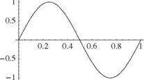
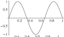
or any constant times фі (x). It can be observed from this function (Fig. 3.1) that the higher the mode number i, the more crossings of the zero axis on the interval 0 < x < І. These crossings are sometimes referred to as “nodes.” The trend of in­creasing numbers of nodes with an increase in the mode number is generally true in structural dynamics.

In the previous solution for the total displacement, each mode shape is multiplied by a function of time. This multiplier is called the “generalized coordinate” and is represented here by ^ (t). For this specific problem, the generalized coordinates are

Подпись: (3.25)§i (t) = Ei sin (ait) + Fi cos (ait)

and thus are seen to be simple harmonic functions of time with frequencies ai. Because there were no external loads applied to the string, the preceding result is

Подпись: 02 (X)Подпись:Standing Wave (Modal) Solution

Standing Wave (Modal) Solution Подпись: X 1 Standing Wave (Modal) Solution

Figure 3.1. First three mode shapes for vibrating string

called the “homogeneous solution.” Had there been an external loading, the resulting time dependency of the generalized coordinates would reflect it.

Thus, the total string displacement can be written as a sum of “modal” contri­butions of the form

v(x, t) = Фі (x)Hi (t) (3.26)

І =1

This expression can be interpreted as a weighted sum of the mode shapes, each of which has a modal amplitude (i. e., the generalized coordinate) that is a function of time. For the homogeneous solution obtained here, this time dependency is simple harmonic at a frequency that is unique for each mode or eigenvalue. These are called the “natural frequencies” of the modes, or “modal frequencies,” and are represented by m. For the string, they are

with the lowest frequencies given by the lowest mode numbers. Indeed, just as the increase in the number of nodes with the mode number is generally true, so it is with

the natural frequency. When the physical and geometric parameters of the problem are expressed in any consistent1 set of units, the units of the natural frequency are rad/sec. Division by 2n converts the units of frequency into “cycles per second,” or Hertz. The inverse of the natural frequency in Hertz is the period of the oscillatory motion.

To summarize what has been accomplished in solving the wave equation, it may be said that the string displacement as a function of both x and t can be represented as a sum of modal contributions. Each mode in this representation is a structural dynamic property of the given system (i. e., string) and can be described completely by mode shape and modal frequency. Such “modes of vibration” can be formulated for any linearly elastic structure that is a conservative system. This statement includes two restrictions that must be observed for a modal representation: (1) linearity, which is satisfied here by the linear wave equation; and (2) the system must be conservative, which means that there can be no addition or dissipation of energy in free vibration. A typical violation of the second restriction is the existence of damping, such as structural or aerodynamic damping. When damping is present, it can be adequately treated as an external loading. Mode shapes are determined only by the solution of homogeneous equations and, in general, they are real only for self-adjoint equations.