Category Introduction to Structural Dynamics and Aeroelasticity

Sweep Effects

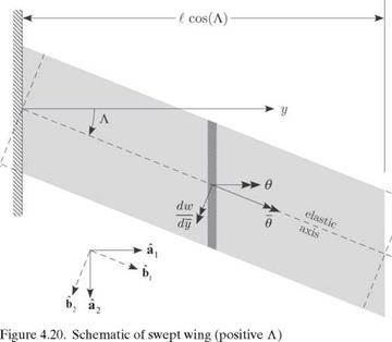
To observe the effect of sweeping a wing aft or forward on the aeroelastic charac­teristics, it is presumed that the swept geometry is obtained by rotating the surface about the root of the elastic axis, as illustrated in Fig. 4.20. The aerodynamic re­actions depend on the angle of attack as measured in the streamwise direction as

a = ar + в (4.89)

where в is the change in the streamwise angle of attack caused by elastic deformation. To develop a kinematical relationship for в, we introduce the unit vectors a1 and a2, aligned with the y axis and the freestream, respectively. Another set of unit vectors, b1 and b2, is obtained by rotating a1 and a2 by the sweep angle Л, as shown in Fig. 4.20, so that b1 is aligned with the elastic axis (i. e., the y axis). From Fig. 4.20, we see that

Подпись: (4.90)

Sweep Effects

b1 = cos^^ + sin^)a2 b2 =- sin^^ + cos^)a2

Observe that the total rotation of the local wing cross-sectional frame caused by elastic deformation can be written as the combination of rotations caused by wing
torsion, в about bi, and wing bending, dw/dy about b2, where w is the bending deflection (positive up, which in Fig. 4.20 is out of the paper). Now, в is the component of this total rotation about jq; that is

Подпись: вdw ■ . л

в bi + — b2 ) ■ ai

Подпись:

Sweep Effects
Sweep Effects

в cos(A) – ddWW sin(A)

From this relationship, it can be noted that as the result of sweep, the effective angle of attack is altered by bending. This coupling between bending and torsion affects both the static aeroelastic response of the wing in flight as well as the conditions under which divergence occurs. Also, it can be observed that for combined bending and torsion of a swept, elastic wing, the section in the direction of the streamwise airflow exhibits a change in camber—a higher-order effect that is here neglected.

Sweep Effects Sweep Effects Подпись: (4.92)

To facilitate direct comparison with the previous unswept results, to the extent possible, the same structural and aerodynamic notation is retained as was used for the unswept planform. To determine the total elastic deflection, two equilibrium equations are required: one for torsional moment equilibrium as in the unswept case and one for transverse force equilibrium (associated with bending). These equations can be written as

In these equilibrium equations, a is used to denote the two-dimensional lift-curve slope of the swept surface and cmac to represent the two-dimensional pitching- moment coefficient of the swept surface. These aerodynamic constants are related to their unswept counterparts by

Подпись: (4.93)a = a cos(A)

cmac = cmac cos (A)

for moderate – to high-aspect-ratio surfaces. Substituting for a, a = ar + в and, in turn, the dependence of в on в and w from Eq. (4.91), specializing for spanwise uniformity so that GJ and EI are constants, and letting ()’ denote d()/dy, we obtain two coupled, ordinary differential equations for torsion and bending given by

в a + q^ в cos2(A) – qffw’ sin(A)cos(A)

1

= -^= [qecaar cos(A) + qc2cmac cos2(A) – Nmgd]

GJ

w"" + =w’ sin(A) cos(A) – qcaв cos2(A) = = [qcaar cos(A) – Nmg] (4.94)

EI EI EI

Because the surface is built in at the root and free at the tip, the following boundary conditions must be imposed on the solution:

y = 0:

в

=0

(zero torsional rotation)

w

=0

(zero deflection)

y = t:

w’

в’

=0

=0

(zero bending slope) (zero twisting moment)

(4.95)

w"

=0

(zero bending moment)

w"’

‘ = 0

(zero shear force)

Bending-torsion coupling is exhibited in Eqs. (4.94) through the term involving w in the torsion equation and through the term involving в in the bending equation.

There are two special cases of interest in which the coupling either vanishes or is much simplified so that we can solve the equations analytically. The first is for the case of vanishing sweep in which the uncoupled torsion equation (i. e., the first of Eqs. [4.94]) is the same as previously discussed and clearly leads to solutions for either the torsional divergence condition or the torsional deformation and air­load distribution as discussed (see Sections 4.2.3 and 4.2.4, respectively). In the latter case, once the torsional deformation is obtained, the solution for в = в can be substituted into the bending equation (i. e., the second of Eqs. [4.94]). Integra­tion of the resulting ordinary differential equation and application of the boundary conditions lead to the shear force, bending moment, bending slope, and bending deflection.

A second special case occurs when e = 0. In this case, torsional divergence does not take place, and a polynomial solution for в can be found from the в equation and boundary conditions. Substitution of this solution into the bending equation leads
to a fourth-order, ordinary differential equation for w with a polynomial forcing function; note that the в terms are now part of that forcing function. This equation and accompanying boundary conditions can be solved for the bending deflection, but the solution is not straightforward. Alternatively, to solve this equation for a divergence condition, we need only the homogeneous part, which can be written as a third-order equation in Z = w’; namely

ZZ sin(A) cos(A) = 0 (4.96)

EI

For the clamped-free boundary conditions Z (0) = Z ‘(0 = Z"CO = 0, this equation has a known analytical solution that yields a divergence dynamic pressure of

Подпись: EI

Подпись: qD = -6.32970-

Sweep Effects

, — (4.97)

acl3 sin(A) cos(A)

The minus sign implies that this bending-divergence instability takes place only for forward-swept wings; that is, where A < 0.

Sweep Effects Подпись: to Подпись: qea в cos2(A) GJ K J Подпись: (4.98)

Examination of Eqs. (4.94) illustrates that there are two ways in which the sweep influences the aeroelastic behavior. One way is the loss of aerodynamic effectiveness, as exhibited by the change in the second term of the torsion equations from

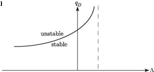
Note that this effect is independent of the direction of sweep. The second effect is the influence of bending slope on the effective angle of attack (see Eq. 4.91), which leads to bending-torsion coupling. This coupling has a strong influence on both divergence and load distribution. The total effect of sweep depends strongly on whether the surface is swept backward or forward. This can be illustrated by its influence on the divergence dynamic pressure, qD, as shown in Fig. 4.21. It is apparent that forward sweep causes the surface to be more susceptible to divergence, whereas backward sweep increases the divergence dynamic pressure. Indeed, a small amount of backward sweep (i. e., for the idealized case under consideration, depending on ell and GJ/ EI, only 5 or 10 degrees) can cause the divergence dynamic pressure to become sufficiently large that it ceases to be an issue. Specific cases are discussed later in this section in conjunction with an approximate solution of the governing equations.

Figure 4.22. Lift distribution for positive, zero, and negative A
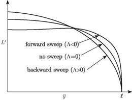
Sweep EffectsThe overall effect of sweep on the aeroelastic-load distribution also strongly depends on whether the surface is swept forward or backward. This is illustrated in Fig. 4.22, which shows spanwise load distributions for an elastic surface for which the total lift (or N) is held constant by adjusting ar. From the standpoint of structural loads, it is apparent that the root bending moment is significantly greater for forward sweep than for backward sweep at a given value of total lift.

The primary motivation for sweeping a lifting surface is to improve the vehicle performance through drag reduction, although some loss in lifting capability may be experienced. However, these aeroelastic considerations can have a significant impact on design decisions. From an aeroelastic standpoint, forward sweep exacerbates divergence instability and increases structural loads, whereas backward sweep can alleviate these concerns. The advent of composite lifting surfaces enabled the use of bending-twist elastic coupling to passively stabilize forward sweep, making it possible to use forward-swept wings. Indeed, the X-29 could not have been flown without a means to stabilize the wings against divergence. We discuss this further in Section 4.2.7.

Exact Solution for Bending-Torsion Divergence. Extraction of the analytical solu­tion of the set of coupled, ordinary differential equations in Eqs. (4.94) is compli­cated. The exact analytical solution is obtained most easily by first converting the coupled set of equations into a single equation governing the elastic component of the angle of attack. For calculation of only the divergence dynamic pressure, we can consider just the homogeneous parts of Eqs. (4.94):

Подпись: (4.99)в" + qecaв cos2(A) – qecaw’ sin(A) cos(A) = 0 GJ GJ

,,,, qca qca 2„

w + w sin(A) cos(A) – в cos2(A) = 0

EI EI

To obtain a single equation, we differentiate the first equation with respect to y and multiply it by cos(A). From this modified first equation, we subtract sin(A) times the
second equation, replacing в cos(A) – w’ sin(A) with в, to obtain

в+ q=a cos2(A)e7 + sin(A) cos(A)e = 0 (4.100)

Introducing a dimensionless axial coordinate n = y/t, this is equation can be written as

в+ qead cos2(A)e’ + sin(A) cos(A)e = 0 (4.101)

GJ EI

where () now denotes d()/dn. The boundary conditions can be derived from Eqs. (4.95) as

в(0) = в'(1) = в"(1) + qqeecaL. cos2(A)e (1) = 0 (4.102)

GJ

Here, the first of Eqs. (4.99) and the final boundary condition from Eqs. (4.95) are used to derive the third boundary condition.
Sweep Effects
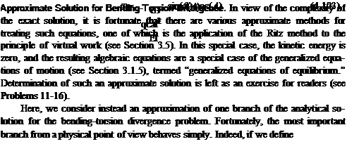
The exact solution for Eqs. (4.101) and (4.102) was obtained by Diederich and Budiansky (1948). Its behavior is complex, with multiple branches, and it is not used easily in a design context. However, a simple approximation of one branch is presented next and compared with plots of the exact solution.

then, as shown by Diederich and Budiansky (1948), the divergence boundary can be approximately represented within a certain range in terms of a straight line

n 2 3n 2

тя = T + 1ъ в° (4.104)

2

Note that for a wing rigid in bending, we have во = 0 and, thus, td = Пр which is the exact solution for pure torsional divergence. Also, for a torsionally rigid wing, we have td = 0 and, thus, eD = -19/3, which is very close to -6.3297, the exact solution for bending divergence. For the cases in between, the error is quite small.

It is important to note that the sign of т is driven by the sign of e, whereas the sign of в is driven by the sign of Л. The approximate solution in Eq. (4.104) is plotted along with some branches of the exact solution in Fig. 4.23. Note the excellent agreement between the straight-line approximation and the exact solution near the origin. Note also that the intersections of the solution with the td axis (where во = 0) coincide with the squares of the roots previously obtained in Section 4.2.3, Eq. (4.63), as (2n – 1)2n 2/4 for n = 1, 2,…, ж (i. e., n 2/4, 9n 2/4,…).

A more convenient way of depicting the behavior of the divergence dynamic pressure is to plot тD versus a parameter that depends on only the configuration. This can be accomplished by introducing the dimensionless parameter r, given by

Подпись: (4.105)в t GJ

r = = tanm

т e EI

Sweep Effects Подпись: (4.106)

which can be positive, negative, or zero. Equation (4.104) can then be written as

Sweep Effects Sweep Effects

Thus, we can solve for td such that

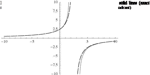
Several branches of the exact solution of Eqs. (4.101) and (4.102) for the smallest absolute values of td versus r are plotted as solid lines in Fig. 4.24. Note that there is
Sweep Effects

at least one branch in all quadrants except the third, and there is only one branch in the fourth quadrant. The approximate solutions for td versus r from Eq. (4.107) are plotted as dashed hyperbolae in the first, second, and fourth quadrants. Moreover, as r becomes large, the solution in the fourth quadrant asymptotically approaches the parabola td = -27r2/4, also shown as a dashed curve. Note that as in Fig. 4.23, the intersections of the roots with the тD axis are n2/4,9n2/4,25n2/4, and so on. The configuration of any wing fixes the value of r. For positive e, we consider only positive values of td. Thus, we start from zero and proceed in the positive td direction on this plot (i. e., at constant r) to find the first intersection with a solid line. This value of td is the normalized dynamic pressure at which divergence occurs. In Fig. 4.25,

an enlargement of these results in a more practical range is shown. It is easily seen that the dashed lines in the first and second quadrants are close to the solid lines when r < 1.5. Note that when e < 0, a negative value of td leads to a positive value of qD. In this case, we should proceed along a line of constant r in the negative td direction.

It is interesting that the approximate solution, despite its proximity to the exact solution, exhibits a qualitatively different behavior mathematically. The approximate solution exhibits an asymptotic behavior, with td tending to plus infinity from the left and to minus infinity from the right at the value of r that causes the denominator to vanish—namely, when r = 76/(3n2) = 2.56680. If the approximate solution were exact, mathematically it would mean that divergence is not possible at that value of r. Moreover, physically it would mean that divergence is not possible for e > 0 and r > 76/(3n2) [or for e < 0 and r < 76/(3n2)]. Actually, however, the exact solution exhibits an instability of the “limit-point” variety. For e > 0, this means that divergence occurs for small and positive values of r. Moreover, as r is increased in the first quadrant, td also increases until a certain point is reached, at which two things happen: (1) above this value of td, the curve turns back to the left instead of reaching an asymptote; and (2) any slight increase in r beyond this point causes the solution to jump to a higher branch. This point is called a limit point. On the main branch of the curve in the first quadrant, for example, the limit point is at r = 1.59768 and td = 10.7090. It is shown in the plot in Fig. 4.24 that any slight increase in r causes the solution to jump from the lower branch—where its value is 10.7090—to a higher branch, where its value is 66.8133, at which point td is rapidly increasing with r. So, although there is no value of r that results in an infinite exact value of the divergence dynamic pressure, practically speaking, divergence in the vicinity of the limit-point value of r is all but eliminated. Thus, it is sufficient for practical purposes to say that divergence is not possible near those points where the approximate solution blows up, and we may regard the approximate solution as sufficiently close to the exact solution for design purposes. The limit point in the fourth quadrant is appropriate for the situation in which e < 0—namely, when the aerodynamic center is behind the elastic axis. There, the exact limit point is at r = 3.56595 and тD = -14.8345. Note that the negative values of e and td yield a positive qD. It is left to readers as an exercise to explore this possibility further (see Problem 18).

Although there are qualitative differences, as noted, between the exact and ap­proximate solutions, within the practical range of interest, this linear approximation of the divergence boundary in terms of td and вD is numerically accurate and leads to a simple expression for the divergence dynamic pressure in terms of the structural stiffnesses, e/t, and the sweep angle (i. e., Eq. [4.108]). This approximate formula can be used in design to explore the behavior of the divergence dynamic pressure as a function of the various configuration parameters therein. For the purpose of displaying results for the divergence dynamic pressure when e > 0, it is convenient to normalize qD with its value at zero sweep angle; namely

Подпись: (4.109)n 2 GJ qD° 4ecat2

Подпись: 4D

Подпись: so that Подпись: qp 1 + tan2(A) qp0 = 1 - 3621GEJ tan(A) Подпись: (4.110)

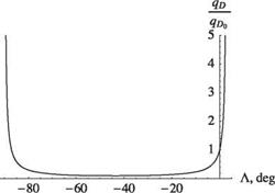
Figure 4.26. Normalized divergence dynamic pres­sure for an elastically uncoupled, swept wing with GJ/EI = 1.0 and e/l = 0.02

Подпись: tan (Лто) Подпись: 76 Ele 3n 2 GJ l Подпись: (4.111)

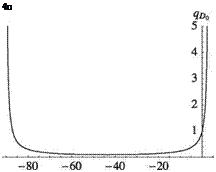
Thus, for a wing structural design with given values of e, GJ, EI, and l, there are values of sweep angle Л for which the divergence dynamic pressure goes to infinity or becomes negative, implying that divergence is not possible at those values of Л. Some values of Л make the numerator infinite because tan^) blows up, whereas other values make the denominator vanish or switch signs. Therefore, within the principal range of -90° < Л < 90°, we can surmise that divergence can take place only for cases in which |Л| = 90° and 3n2r = 76. Sign changes have the following consequences: Divergence is possible only if -90° < Л < Лто, where

Thus, Eq. (4.110) can be written as

Подпись:Подпись: (4.112)0p_

qP0

In other words, we avoid divergence by choosing Л > Лто, and the divergence dy­namic pressure drops drastically as Л is decreased below Лто. Because Лто is likely to be small, this frequently means that backswept wings are free of divergence and that divergence dynamic pressure drops drastically for forward-swept wings. Because Лто is the asymptotic value of Л from the approximate solution, which is greater than the limit-point value of Л from the exact solution, we may surmise that the approx­imate solution provides a conservative design. Figure 4.26 shows the behavior of divergence dynamic pressure for a wing with GJ /EI = 1.0 and e/l = 0.02. The plot, as expected, passes through unity when the sweep angle is zero. Because Лто is very small for this case, the divergence dynamic pressure goes to infinity for a very small positive value of sweep angle. Thus, even a small angle of backward sweep can make divergence impossible. Figure 4.27 shows the result of decreasing GJ/EI to 0.2 and holding e/l constant. Because Лто increases, the wing must be swept back farther than in the previous case to avoid divergence.

Figure 4.27. Normalized divergence dynamic pres­sure for an elastically uncoupled, swept wing with GJ/EI = 0.2 and e/l = 0.02
Sweep EffectsBecause e can be positive, negative, or zero, qD0 also may be positive, negative, or zero. Thus, by normalizing qD by qD0, we may obfuscate the role of the sign of e on qD. In such cases and perhaps others, it is more convenient to write Eq. (4.112) in a form that does not depend on qD0. One way to accomplish this is to eliminate qD0 from the expression for qD using Eqs. (4.109) and (4.111), yielding

goad _ 19 [1 + tan2 (Л)] (4 _

EI 3 [tan^cx,) – tan^)] .

making it clearer that divergence occurs only when -90° < Л < Лх, regardless of the sign of e. This form of the formula also shows more explicitly that EI has a role in the design of swept wings that are free of divergence.

Aileron Reversal

In Section 4.1.4, an example illustrating aileron reversal is presented based on a rigid, two-dimensional wing with a flexible support. In this section, we examine the same physical phenomenon using a torsionally flexible wing model. With the geometry and boundary conditions of the uniform, torsionally flexible lifting surface as before, we can derive the reversal dynamic pressure for a clamped-free wing. Two logical choices are presented regarding the defining condition. One is to define reversal dynamic pressure as that dynamic pressure at which the change of total lift with respect to the aileron deflection is equal to zero. Another equally valid definition is to define it as the dynamic pressure at which the change in root-bending moment with respect to the aileron deflection is equal to zero. Finally, we look at the effectiveness of ailerons for roll control—often termed the “roll effectiveness”—of a simplified flying aircraft model.

Note that the presence of an aileron requires that we modify the sectional lift and pitching moment coefficients, so that

Подпись: (4.72)ci = aa + сівв cmac = сшрв

Using these coefficients and setting ar equal to zero, the sectional lift and pitching moment are given by

Подпись: (4.73)L = qc (ав + сів M = eL + qc2cm/)P

where we assume that the aileron extends along the entire length of the wing. As­suming the weight to have a negligible effect on the reversal condition, the modified version of Eq. (4.49) is written as

— + х2в = – X2fp (4.74)

dy2

We may refine the theoretical result by considering a simplified correction from three-dimensional effects by use of a tip-loss factor, typically chosen as B = 0.97. Instead of obtaining the total lift by integrating the sectional lift over the entire wing length from y = 0 to y = £, we integrate only from y = 0 to y = B£.

d[6]e1

dy2

d292

dy2

d%

dy2

+ Х2в1 = 0 + Х2в2 = – + Х2в3 = 0

Х2фв r£ < y < R£

Aileron Reversal Подпись: (4.81)

Similarly, we may account for an aileron that does not extend over the entire length of the wing. Suppose that the aileron starts at y = r £ and extends to y = R£ with 0 < r < R < 1. This means that there are as many as three segments to be analyzed. There is no inhomogeneous term for the segments between y = r£ and y = R£, so instead of Eq. (4.74), we write

and obtain the resulting six arbitrary constants by imposing the six boundary conditions

01(0) = 0 0l(r l) = в2(г l)

d01 , , d02, .

d7(r l) = d7(r l)

Подпись: (4.82)

Aileron Reversal

02( Rl) = 03( Rl)

Calculation of the reversal dynamic pressure from the second definition (i. e., the one in terms of the root-bending-moment criterion) is left as an exercise for readers (see Problem 20).

This treatment can be generalized easily to consider the roll effectiveness of a complete aircraft model. Similar problems can be posed in the framework of dynamics, in which the objective is, say, to predict the angular acceleration caused by deflection of a control surface, or the time to change the orientation of the aircraft from one roll angle to another. Depending on the aircraft and the maneuver, it may be necessary to consider nonlinearities. Here, however, only a static, linear treatment is included.

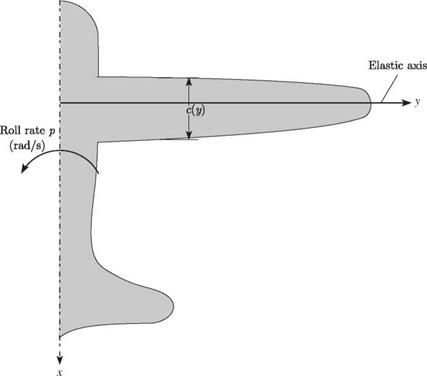
Consider a rolling aircraft with unswept wings, the right half of which is shown in Fig. 4.16, with a constant roll rate denoted by p. As shown in Fig. 4.17, the wing section has an incidence angle with respect to the freestream velocity of ar + 0 (y). In a roll maneuver with p > 0, the right wing moves upward while the left wing moves downward. The right wing then “sees” an additional component of wind velocity equal to py perpendicular to the freestream velocity and downward. As shown in Fig. 4.17, because py < U, the angle of attack is reduced from the incidence angle to ar + 0 – py/U.

Some contributions to the lift and pitching moment are the same (opposite) on both sides of the aircraft; these are referred to as symmetric (antisymmetric) com­ponents. Separate problems can be posed in terms of symmetric and antisymmetric parts, which are generally uncoupled from one another. In particular, we can treat the roll problem as an antisymmetric problem noting that all symmetric components cancel out in pure roll. Hence, we can discard them a priori. For example, in the relationship

a = af+ 0 (y) – U (4.83)

the first term, ar, drops out because of symmetry. Both 0 (y) and the roll-rate term are antisymmetric because 0 and в have the opposite sense across the mid-plane of the aircraft. The last term, which represents the increment in the angle of attack from

Aileron Reversal

Figure 4.16. Schematic of a rolling aircraft

the roll rate p based on the assumption of a small angle of attack, also is explicitly antisymmetric.

Assuming c(y) to be a constant, c, we may write the governing differential equation as

|2 + Х2в = X2 (U – e) (4.84)

with boundary conditions в (0) = de/dy(l) = 0. The solution is given by

в = P[Xy – sec(X£) sin(Xy)] + ffi[tan(Xl) sin(Xy) + cos(Xy) – 1] (4.85)

Aileron Reversal

Figure 4.17. Section of right wing with positive aileron deflection

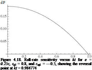
Подпись: dP Figure 4.18. Roll-rate sensitivity versus kt for e = 0.25c, ctjl = 0.8, and cmf, = —0.5, showing the reversal point at kt = 0.984774

C)

Now, because the aircraft is in a steady-state rolling motion, the total rolling moment must be equal to zero. Thus, ignoring the offset of the wing root from the mid-plane of the aircraft, we may find the moment of the lift about the mid-plane of the aircraft

Aileron Reversal Подпись: (4.86)

as

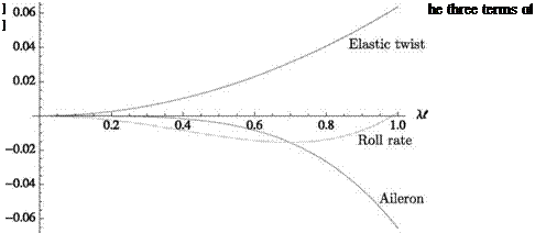
which, when set equal to zero, can be solved for the constant roll rate p. (Note that the three terms in Eq. [4.86] are the contributions toward the rolling moment due to the elastic twist, the roll rate p, and the aileron deflection в, respectively.) This result, written here in dimensionless form as pt/U, is given by

pt _ kt [ccmf) [(kt)2 – 2sec(kt) + 2] – 2ectp [sec(kt) – 1]} в 87)

U 2ae[kt — tan(kt)] .

which is proportional to в. At a certain dynamic pressure, we are unable to change the roll rate by changing в. This dynamic pressure occurs when the sensitivity of the roll rate to в vanishes; viz.

9 (U) kt {ccmв [(kt)2 — 2 sec(kt) + 2] — 2ect^ [sec(kt) — 1] } 0

дв 2ae[kt — tan(kt)] ( . )

For specific values of e/c and the sectional airfoil coefficients ctf and cmf), we may numerically solve this equation for a set of roots for kt. The lowest value is associated the aileron reversal. Alternatively, we simply may plot the quantity in Eq. (4.88) versus kt until it changes sign, which is the reversal point.

For a specific case (i. e., e = 0.25c, ctв = 0.8, and cmв = -0.5), the roll-rate sen­sitivity is shown versus kt, which is proportional to the speed U, in Fig. 4.18, which shows the reversal point at kt = 0.984774. Notice that the curve at low speed starts
as relatively flat and monotonically decreases until the reversal point is reached. This shape is a typical result and shows the importance of static aeroelasticity in this aspect of flight mechanics. It is also interesting to observe the relative contributions to the rolling moment from the elastic twist, the rolling motion, and the aileron deflections depicted in Fig. 4.19. At the reversal point, p vanishes, and the rolling moment contributions from elastic twist and from aileron deflection exactly cancel out one another.

Airload Distribution

It has been observed that the spanwise-lift distribution can be determined as

L = qca(ar + в) (4.66)

where we recall from Eq. (4.52) that

в = (ar + ar) [tan(Xl) sin(Xy) + cos(Xy) – 1] (4.67)

and where ar is given in Eq. (4.48). If the lifting surface is a wind-tunnel model of a wing and is fastened to the wind-tunnel wall, then the load factor, N, is equal to unity and ar can be specified. The resulting computation of L is straightforward.

If, however, the lifting surface represents half the wing surface of a flying vehicle, the computation of L is not as direct. Note that the constant ar is a function of N. Thus, for a given value of ar, there is a corresponding distribution of elastic twist and a particular airload distribution. This airload can be integrated over the vehicle to obtain the total lift, L. Recall that N = L/ W, where W is the vehicle weight. It is thus apparent that the load factor, N, is related to the rigid angle of attack, ar,

Airload Distribution Airload Distribution

through the elastic twist angle, в. For this reason, either of the two variables ar and N can be specified; the other then can be obtained from the total lift L. Assuming a two-winged vehicle with all the lift being generated from the wings, we find

Airload Distribution Подпись: (4.70)

Because N = L/ W, this expression can be divided by the vehicle weight to yield a relationship for N in terms of ar and ar. This relationship then can be solved simultaneously with the preceding expression for ar, Eq. (4.48), in terms of ar and N. In this manner, ar can be eliminated, providing either a relationship that expresses N in terms of ar, given by

Airload Distribution Airload Distribution Подпись: Nmgi2d CCmac " GJ(Ai)2 ae _ Подпись: (4.71)

or a relationship that expresses ar in terms of N

These relationships permit us to specify a constant ar and find N(q) or, alternatively, to specify a constant N and find ar(q). We find that N(q) starts out at zero for q = 0. Conversely, ar(q) starts out at infinity for q = 0. The limiting values as q ^ qD depend on the other parameters. These equations can be used to find the torsional deformation and the resulting airload distribution for a specified flight condition.

The calculation of the spanwise aeroelastic airload distribution is immensely practical and is used in industry in two separate ways. First, it is used to satisfy a requirement of aerodynamicists or performance engineers who need to know the total force and moment on the flight vehicle as a function of altitude and flight condition. In this instance, the dynamic pressure q (and altitude or Mach number) and ar are specified, and the load factor N or total lift L is computed using Eq. (4.70).

A second requirement is that of structural engineers, who must ensure the struc­tural integrity of the lifting surface for a specified load factor N and flight condition. Such a specification normally is described by what is called a V-N diagram. For the conditions of given load factor and flight condition, it is necessary for structural engineers to know the airload distribution to conduct a subsequent loads and stress analysis. When q (and altitude or Mach number) and N are specified, ar is then determined from Eq. (4.71). Knowing q, ar, and N, we then use Eq. (4.48) to find ar. The torsional deformation, в, then follows from Eq. (4.67) and the spanwise-airload

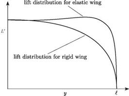
Figure 4.14. Rigid and elastic wing-lift distribu­tions holding ar constant

Airload Distributiondistribution follows from Eq. (4.66). From this, the distributions of torsional and bending moments along the wing can be found, leading directly to the maximum stress in the wing, generally somewhere in the root cross section.
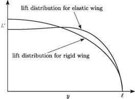
Observe that the overall effect of torsional flexibility on the unswept lifting surface is to significantly change the spanwise-airload distribution. This effect can be seen as the presence of the elastic part of the lift coefficient, which is proportional to в(y). Because this elastic torsional rotation generally increases as the distance from the root (i. e., out along the span), so also does the resultant airload distribution. The net effect depends on whether ar or N is specified. If ar is specified, as in the case of a wall-mounted elastic wind-tunnel model (N = 1) or as in performance computations, then the total lift increases with the additional load appearing in the outboard region, as shown in Fig. 4.14.

In the other case, when N is specified by a structural engineer, the total lift (i. e., area under L versus y) is unchanged, as shown in Fig. 4.15. The addition of lift in the outboard region must be balanced by a decrease inboard. This is accomplished by decreasing ar as the surface is made more flexible.

Airload DistributionFigure 4.15. Rigid and elastic wing-lift distribu­tions holding total lift constant

All of the preceding equations for torsional divergence and airload distribu­tion were based on a strip-theory aerodynamic representation. A slight numerical improvement in their predictive capability can be obtained if the two-dimensional lift-curve slope, a, is replaced everywhere by the total (i. e., three-dimensional) lift – curve slope. Although there is little theoretical justification for this modification, it alters the numerical results in the direction of the exact answer. Also, it is important to note that the lift distributions depicted in Figs. 4.14 and 4.15 cannot be generated with strip-theory aerodynamics because strip theory fails to pick up the dropoff of the airload to zero at the wing tip caused by three-dimensional effects. An aero­dynamic theory at least as sophisticated as Prandtl’s three-dimensional lifting-line theory must be used to capture that effect. In such a case, closed-form expressions such as those of Eqs. (4.70) and (4.71) cannot be obtained; instead, it is necessary to use numerical methods to find N as a function of ar or ar as a function of N.

Torsional Divergence

If it is presumed that the configuration parameters of the uniform wing are known, then it is possible to solve Eq. (4.45) to determine the resulting twist distribution and associated airload. To simplify the notation, let

Подпись:qcae

Подпись: (4.47)~w

1

== (qc2cmac – Nmgd) GJ

Torsional Divergence

so that

Note that X2 and ar are independent of y because the wing is assumed to be uniform. The static-aeroelastic equilibrium equation now can be written as

d26 t

—— + х2в = – X2 (ar + ar) (4.49)

dy2

The general solution to this linear ordinary differential equation is

в = Asin(Xy) + B cos(Xy) – (ar + ar) (4.50)

subject to the condition that X = 0. Applying the boundary conditions, we find that

Подпись: (4.51)Подпись: (4.52)в (0) = 0: B = ar + ar

в'(£) = 0: A = B tan(X£)

where () = d()/dy. Thus, the elastic-twist distribution becomes в = (ar + ar) [tan(X£) sin(Xy) + cos(Xy) – 1]

Because в is now known, the spanwise-lift distribution can be found using the relationship

Подпись: (4.53)L’ = qca(ar + в)

It is important to note from the expression for elastic twist that в becomes infinite as XI approaches n/2. This phenomenon is called “torsional divergence” and depends on the numerical value of

X = M (4’54)

Thus, it is apparent that there exists a value of the dynamic pressure q = qD, at which XI equals n/2, where the elastic twist theoretically becomes infinite. The value qD is called the “divergence dynamic pressure” and is given by

GJ / n 2 qD eca 2£/

(4.55)

Noting now that we can write

x£ = n yq

(4.56)

with

4 §

и

(4.57)

the twist angle of the wing at the tip can be written as

в(£) = (ar + ar) [sec(X£) – 1]

= (ar + ar) sec (2^) – 1

Torsional Divergence

q


1.0


0.2 0.4 0.6 0.8


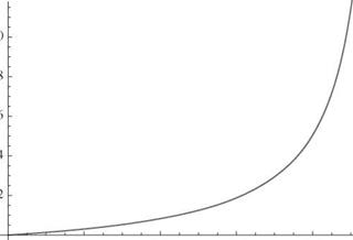
Figure 4.13. Plot of twist angle for the wing tip versus q for ar + ar = 1


Torsional Divergence

where Eq. (4.48) now can be written as

Torsional Divergence

(4.59)


Letting d be zero so that ar becomes independent of q, we can examine the behavior of в (£) versus q. Such a function is plotted in Fig. 4.13, where we see that the tip-twist angle goes to infinity as q approaches unity. Note that the character of the plot in Fig. 4.13 is similar to the prebuckling behavior of columns that have imperfections. It is of practical interest to note that the tip-twist angle may become sufficiently large to warrant concern about the structural integrity for dynamic pressures well below qD. In practice, designers normally require the divergence dynamic pressure to be outside of the vehicle’s flight envelope—perhaps by specifying an appropriate factor of safety.

Because this instability occurs at a dynamic pressure that is independent of the right-hand side of Eq. (4.49), as long as the right-hand side is nonzero, it seems possible that the divergence condition could be obtained from the homogeneous equilibrium equation

Torsional Divergence(4.60)

The general solution to this eigenvalue problem of the Sturm-Liouville type is

Подпись: (4.61)в = Asin(Xy) + B cos(Xy)

for X = 0. Applying the boundary conditions, we obtain

в (0) = 0: B = 0

в ‘(£) = 0: AX cos(X-f) = 0

If A = 0 in the last condition, there is no deflection; this is a so-called trivial solu­tion. Because X = 0, a nontrivial solution is obtained when cos(Xl) = 0. This is the “characteristic equation” with solutions given by

Xnl = (2n – 1) 2 (n = 1, 2,…) (4.63)

These values are called “eigenvalues.” This set of values for Xnl corresponds to a set of dynamic pressures

q=(2n – ч2(Ц)2 G (n=12-o (4-64)

The lowest of these values, q, is equal to the divergence dynamic pressure, qD, pre­viously obtained from the inhomogeneous equilibrium equation. This result implies that there are nontrivial solutions of the homogeneous equation for the elastic twist. In other words, even for cases in which the right-hand side of Eq. (4.49) is zero (i. e., when ar + ar = 0), there is a nontrivial solution

0n = An sin(Xn^) (4.65)

for each of these discrete values of dynamic pressure. Because An is undetermined, the amplitude of en is arbitrary, which means that the effective torsional stiffness is zero whenever the dynamic pressure q = qn. The mode shape в is the divergence mode shape, which must not be confused with the twist distribution obtained from the inhomogeneous equation.

If the elastic axis is upstream of the aerodynamic center, then e < 0 and X is imaginary in the preceding analysis. The characteristic equation for the divergence condition becomes cosh(|X|l) = 0. Because there is no real value of X that satisfies this equation, the divergence phenomenon does not occur in this case.

Equilibrium Equation

Because we are analyzing the static behavior of this wing, it is appropriate to simplify the fundamental constitutive relationship of torsional deformation, Eq. (2.42), to read

__ de

T = GJ— (4.42)

dy

where GJ is the effective torsional stiffness and T is the twisting moment about the elastic axis. Now, a static equation of moment equilibrium about the elastic axis

can be obtained by equating the rate of change of twisting moment to the negative of the applied torque distribution. This is a specialization of Eq. (2.43) in which time-dependent terms are ignored, yielding

dT

dy


dy dy


= – M


(4.43)


Recognizing that uniformity implies GJ is constant over the length; substituting Eqs. (4.37) into Eq. (4.35) to obtain the applied torque; and, finally, substituting the applied torque and Eq. (4.42) for the internal torque into the equilibrium equation, Eq. (4.43), we obtain

Подпись: (4.44)—d20 2

GJ—r = – qc2cmac – eqcci + Nmgd dy2

Eq. (4.41) now can be substituted into the equilibrium equation to yield an in­homogeneous, second-order, ordinary differential equation with constant coeffi cients

Подпись: (4.45)d2 в qcae 1 , 2 л

~г~2 + -==- в = -= (qc^mac + qcaear – Nmgd) dy GJ GJ

A complete description of this equilibrium condition requires specification of the boundary conditions. Because the surface is built in at the root and free at the tip, these conditions can be written as

y = 0: в = 0 (zero deflection)

„ de. . . (4.46)

y = t. dy = 0 (zero twisting moment)

Obviously, these boundary conditions are valid only for the clamped-free condition. The boundary conditions for other end conditions for beams in torsion are given in Section 3.2.2.

Steady-Flow Strip Theory

In Section 4.1, wings are assumed to be rigid and two-dimensional. That is, the airfoil geometry including incidence angle is independent of spanwise location, and the span is sufficiently large that lift and pitching moment are not functions of a spanwise coordinate. In turning our attention to wings that can be modeled as isotropic beams, the incidence angle now may be a function of the spanwise coordinate because of the possibility of elastic twist. We need the distributed lift force and pitching moment per unit span exerted by aerodynamic forces along a slender beam-like wing. At this stage, however, we ignore the three-dimensional tip effects associated with wings of finite length; the aerodynamic loads at a given spanwise location do not depend on those at any other.

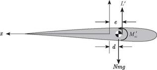
The total applied, distributed, twisting moment per unit span about the elastic axis is denoted as M'(y), which is positive leading-edge-up and given by

M = Ma c + eL — Nmgd (4.35)

where L and M’ac are the distributed spanwise lift and pitching moment (i. e., the lift and pitching moment per unit length), mg is the spanwise weight distribution (i. e., the weight per unit length), and N is the “normal load factor” for the case in which the wing is level (i. e., the z axis is directed vertically upward). Thus, N can be written as

N = W =1 + 7 <436>

where Az is the z component of the wing’s inertial acceleration, W is the total weight of the aircraft, and Lis the total lift.

The distributed aerodynamic loads can be written in coefficient form as

L = qcce
Mac = qc cmac

where the freestream dynamic pressure, q, is

1 9

q = 2 P^u 2 (4.38)

Note that the sectional lift ct and moment cmac coefficients are written here in lower case to distinguish them from lift and pitching moment coefficients for a two­dimensional wing, which are normally written in upper case. Finally, the primes are included with L, M, and M^c to reflect that these are distributed quantities (i. e., per unit span).

The sectional lift and pitching-moment coefficients can be related to the angle of attack a by an appropriate aerodynamic theory as some functions ct(a) and cmac(a), where the functional relationship generally involves integration over the planform. To simplify the calculation, the wing can be broken up into spanwise segments of infinitesimal length, where the local lift and pitching moment can be estimated from two-dimensional theory. This theory, commonly known as “strip theory,” frequently uses a table for efficient calculation. Here, however, for small values of a, we may use an even simpler form in which the lift-curve slope is assumed to be a constant along the span, so that

ce(y) = aa(y) (4.39)

where a denotes the constant sectional lift-curve slope, and the sectional-moment coefficient cmac(a) is assumed to be a constant along the span.

The angle of attack is represented by two components. The first is a rigid con­tribution, ar, from a rigid rotation of the surface (plus any built-in twist, although none is assumed to exist here). The second component is the elastic angle of twist в (y). Hence

a( y) = ar + в (y) (4.40)

where, as is appropriate for strip theory, the contribution from downwash associated with vortices at the wing tip is neglected. Therefore, associated with the angle of attack at each infinitesimal section is a component of sectional-lift coefficient given by strip theory as

Подпись: (4.41)ct (y) = a[ar + в (y)]

Uniform Lifting Surface

So far, our aeroelastic analyses focused on rigid wings with a flexible support. These idealized configurations provide insight into the aeroelastic stability and response, but practical analyses must take into account flexibility of the lifting surface. That be­ing the case, in this section, we address flexible wings, albeit with simplified structural representation.

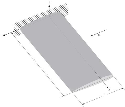
Consider an unswept uniform elastic lifting surface as illustrated in Figs. 4.11 and 4.12. The lifting surface is modeled as a beam and, in keeping with historical practice in the field of aeroelasticity, the spanwise coordinate along the elastic axis is denoted by y. The beam is presumed to be built in at the root (i. e., y = 0, to represent attachment to a wind-tunnel wall or a fuselage) and free at the tip (i. e., y = £). The y axis corresponds to the elastic axis, which may be defined as the line of effective shear centers, assumed here to be straight. Recall that for isotropic beams, a transverse force applied at any point along this axis results in bending with no elastic torsional rotation about the axis. This axis is also the axis of twist in response to a pure twisting moment applied to the wing. Because the primary concern here

z

Uniform Lifting Surface

Figure 4.12. Cross section of spanwise uniform lifting surface

is the determination of the airload distributions, the only elastic deformation that influences these loads is rotation due to twist about the elastic axis.

Wall-Mounted Model for Application to Aileron Reversal

Before leaving the wind-tunnel-type models discussed so far in this chapter, we consider the problem of aileron reversal. “Aileron reversal” is the reversal of the aileron’s expected response due to structural deformation of the wing. For exam­ple, wing torsional flexibility can cause ailerons to gradually lose their effectiveness as dynamic pressure increases; beyond a certain dynamic pressure that we call the “reversal dynamic pressure,” they start to function in a manner that is opposite to their intended purpose. The primary danger posed by the loss of control effectiveness

Wall-Mounted Model for Application to Aileron Reversal

Wall-Mounted Model for Application to Aileron Reversal

Figure 4.10. Schematic of the airfoil section of a flapped two-dimensional wing in a wind tunnel


is that the pilot cannot control the aircraft in the usual way. There are additional concerns for aircraft, the missions of which depend on their being highly maneu­verable. For example, when control effectiveness is lost, the pilot may not be able to count on the aircraft’s ability to execute evasive maneuvers. This loss in control effectiveness and eventual reversal is the focus of this section.

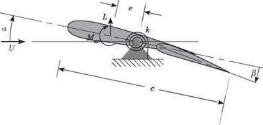
Consider the airfoil section of a flapped two-dimensional wing, shown in Fig. 4.10. Similar to the model discussed in Section 4.1.1, the wing is pivoted and restrained by a rotational spring with spring constant к. The main differences are that (1) a trailing – edge flap is added such that the flap angle в can be arbitrarily set by the flight-control system; and (2) we need not consider gravity to illustrate this phenomenon, so the weight is not shown in the figure. Moment equilibrium for this system about the pivot requires that

Mac + eL = кв (4.24)

The lift and pitching moment for a two-dimensional wing can be written as before; namely

Подпись: (4.25)L = qSCL

Mac = qcSCMac

When в = 0, the effective camber of the airfoil changes, inducing changes in both lift and pitching moment. For a linear theory, both a and в should be small angles, so that

Подпись:cl = CLaa + CLee

CMac = CMo + CM»e

where, as before, the angle of attack is a = ar + в. Note that CMe < 0; for conve­nience, we assume a symmetric airfoil (CM0 = 0).

Note that we may most directly determine the divergence dynamic pressure by writing the equilibrium equation without the inhomogeneous terms; that is

A nontrivial solution exists when the coefficient of в vanishes, yielding the divergence dynamic pressure as

Подпись: (4.28)k

qD =

eSCLa

Clearly, the divergence dynamic pressure is unaffected by the aileron.

Wall-Mounted Model for Application to Aileron Reversal Подпись: (4.29)

Conversely, the response is significantly affected by the aileron, as we now show. We can solve the response problem by substituting Eqs. (4.25) into the moment – equilibrium equation, Eq. (4.24), making use of Eqs. (4.26), and determining в to be

We see that because of the flexibility of the model in pitch (representative of torsional flexibility in a wing), в is a function of в .We then find the lift as follows:

1. Substitute Eq. (4.29) into a = ar + в to obtain a.

2. Substitute a into the first of Eqs. (4.26) to obtain the lift coefficient.

3.

Wall-Mounted Model for Application to Aileron Reversal Wall-Mounted Model for Application to Aileron Reversal Подпись: (4.30)

Finally, substitute the lift coefficient into the first of Eqs. (4.25) to obtain an expression for the aeroelastic lift:

Wall-Mounted Model for Application to Aileron Reversal Подпись: (4.31)

It is evident from the two terms in the coefficient of в in this expression that lift is a function of в in two counteracting ways. Ignoring the effect of the denominator, we see that the first term in the numerator that multiplies в is purely aerodynamic and leads to an increase in lift with в because of a change in the effective camber. The second term is aeroelastic. Recalling that CMe < 0, we see that as в is increased, the effective change in the camber also induces a nose-down pitching moment that— because the model is flexible in pitch—tends to decrease в and in turn decrease lift. At low speed, the purely aerodynamic increase in lift overpowers the aeroelastic tendency to decrease the lift, so that the lift indeed increases with в (and the aileron works as advertised). However, as dynamic pressure increases, the aeroelastic effect becomes stronger; there is a point at which the net rate of change of lift with respect to в vanishes so that

Wall-Mounted Model for Application to Aileron Reversal Подпись: (4.32)

Thus, we find that the dynamic pressure at which the reversal occurs is

Notice that because CM, < 0, qR > 0. Obviously, a stiffer k gives a higher reversal speed, and a model that is rigid in pitch (analogous to a torsionally rigid wing) will

not undergo reversal. For dynamic pressures above qR (but still below the divergence dynamic pressure), a positive в will actually decrease the lift.

Now let us consider the effect of both numerator and denominator. As discussed previously, the divergence dynamic pressure also can be found by setting the denom­inator of L or в equal to zero, resulting in the same expression for qD as found in Eq. (4.27). Equations (4.27) and (4.32) can be used to simplify the expression for the lift in Eq. (4.30) to obtain

Подпись: (4.33)Подпись: LqS[CLaar + CLe (1 – qR) в_

1 – q

rd

It is clear from this expression that the coefficient of в can be positive, negative, or zero. Thus, a positive в could increase the lift, decrease the lift, or not change the lift at all. The aileron’s lift efficiency, n, can be thought of as the aeroelastic (i. e., actual) change in lift per unit change in в divided by the change in lift per unit change in в that would result were the model not flexible in pitch; that is

change in lift per unit change in в for elastic wing

n = ——————————————————–

change in lift per unit change in в for rigid wing

Using this, we can easily find that

1 – q

n = rrf (4.34)

qD

which implies that the wing will remain divergence-free and control efficiency will not be lost as long as q < qD < qR. Obviously, were the model rigid in pitch, both qD and qR would become infinite and n = 1.

Thinking unconventionally for the moment, let us allow the possibility of qR < qD. This will result in aileron reversal at a low speed, of course. Although the aileron now works opposite to the usual way at most operational speeds of the aircraft, this type of design should not be ruled out on these grounds alone. Active flight-control systems certainly can compensate for this. Moreover, we can obtain considerably more (negative) lift for positive в in this unusual regime than positive lift for positive в in the more conventional setting. This concept is a part of the design of the Kaman “servo-flap rotor,” the blades of which have trailing-edge flaps that flap up for increased lift. It also may have important implications for the design of highly maneuverable aircraft. Exactly what other potential advantages and disadvantages exist from following this strategy—particularly in this era of composite materials, smart structures, and active controls—is not presently known and is the subject of current research.

We revisit this problem in Section 4.2.5 from the point of view of a flexible beam model for the wing.

Wall-Mounted Model for Application to Aileron Reversal

Figure 4.11. Uniform unswept clamped-free lifting surface

Strut-Mounted Model

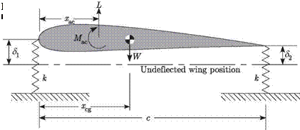
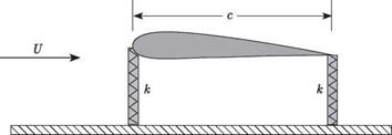
A third configuration of a wind-tunnel mount is a strut system, as illustrated in Figs. 4.8 and 4.9. The two linearly elastic struts have the same extensional stiffness, k, and are mounted at the leading and trailing edges of the wing. The model is mounted in such a way as to have an angle of attack of ar when the springs are both unde­formed. Thus, as before, the angle of attack is а = ar + в. As illustrated in Fig. 4.9, the elastic part of the pitch angle, в, can be related to the extension of the two struts as

c

The sum of the forces in the vertical direction shows that

Подпись: (4.20)Strut-Mounted Model
L – W – Щг + 52) = 0

The sum of the moments about the trailing edge yields

Mac + L(c – Xac) – W(c – Xcg) – kc5i = 0 (4.21)

Strut-Mounted Model Подпись: (4.22)

Again, using Eqs. (4.3) and (4.4) for the lift and pitching moment, the simultaneous solution of the force and moment equations yields

As usual, the divergence condition is indicated by the vanishing of the denominator, so that

Подпись: (4.23)kc

SCLa (1 – 2 Xf)

It is evident for this problem as specified that when the aerodynamic center is in front of the mid-chord (as it is in subsonic flow), the divergence condition cannot be eliminated. However, divergence can be eliminated if the leading-edge spring stiffness is increased relative to that of the trailing-edge spring. This is left as an exercise for readers (see Problem 5).

Sting-Mounted Model

A second configuration of potential interest is a rigid model mounted on an elastic sting. A simplified version of this kind of model is shown in Figs. 4.5 through 4.7, in which the sting is modeled as a uniform, elastic, clamped-free beam with bending

1

в

Sting-Mounted Model

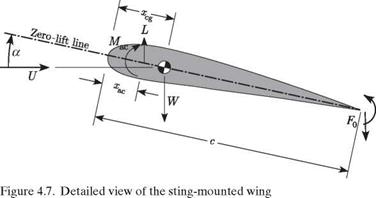
stiffness EI and length Xc, where X is a dimensionless parameter. The model is mounted in such a way as to have angle of attack of ar when the beam is undeformed. Thus, as before, a = ar + в, where в is the nose-up rotation of the wing resulting from bending of the sting, as shown in Fig. 4.6. Also in Fig. 4.6, we denote the tip deflection of the beam as 5, although we do not need it for this analysis. Note the equal and opposite directions on the force F0 and moment M0 at the trailing edge of the wing in Fig. 4.7 versus at the tip of the sting in Fig. 4.6.

Sting-Mounted Model

Figure 4.5. Schematic of a sting-mounted wind-tunnel model

From superposition, we can deduce the total bending slope at the tip of the sting as the sum of contributions from the tip force F0 and tip moment M0, denoted by в F and вм, respectively, so that

Подпись:Подпись: (4.13)

Подпись: Figure 4.6. Detailed view of the clamped-free beam
Sting-Mounted Model

в = eF + вм

From elementary beam theory, these constituent parts can be written as

Sting-Mounted Model

Two static aeroelastic equilibrium equations now can be written for the deter­mination of eF and вм. Using Eqs. (4.3) and (4.4) for the lift and pitching moment,

Sting-Mounted Model

k\\\\\\\\\\\\\\\\\\\\\\\N

Sting-Mounted Model

Figure 4.8. Schematic of strut-supported wind-tunnel model


the force equilibrium equation can be written as

qSC!^ (a + вР + вы) – W — F0 = 0 (4.15)

and the sum of moments about the trailing edge yields

qScCMac + qSCLa (ar + eF + вМ) (c — xac) — W (c — xcg) — M0 = 0 (4.16)

Substitution of Eqs. (4.14) into Eqs. (4.15) and (4.16), simultaneous solution for eF and вМ, and use of Eq. (4.12) yields

Sting-Mounted Model

2rac)


в


(4.17)


Sting-Mounted Model

where rac = xac/c and rcg = xcg/c. Here again, the condition for divergence can be obtained by setting the denominator to zero, so that

qD c2 SA (A + 2 — 2rac) Cta (. )

However, unlike the previous example, we cannot make the divergence dynamic pressure infinite or negative (thereby making divergence mathematically impos­sible) by choice of configuration parameters because xac/c < 1. For a given wing configuration, we are left only with the possibility of increasing the sting’s bending stiffness or decreasing A to make the divergence dynamic pressure larger.