Category BASIC AERODYNAMICS

Role of the Reynolds Number

The Re number was introduced previously (see Chapter 2) as an important viscous-flow similarity parameter that strongly controls the viscous boundary-layer behavior. We now show how this similarity parameter appears as a major governing parameter in the incompressible viscous-flow equations. Steady, two-dimensional Cartesian flow is discussed for convenience, but all results are readily extended to time-dependent flows in three dimensions and to other coordinate systems. Because

The only parameter that appears in the resulting set of dimensionless equations:

Подпись: (8.29) (8.30) (8.31) Подпись:du dw „

й+й=0

_ du _du u — + w—– dx dz

_dw _dw

u — + w — dx dz

is the coefficient (рУ^ L/p) = Re, the Reynolds number. The student should confirm that this also is true for the Navier-Stokes equations that describe three-dimensional flow. Additional dimensionless groups appear if the flow is unsteady or compress­ible. The Re number is a similarity parameter (see Chapter 2).

Suppose that a viscous-flow problem involving a body of given shape and size has a certain numerical value of the Re number and that the Navier-Stokes equations for this problem are written in dimensionless form and solved. Now, consider a second flow problem involving a body of geometrically similar shape (i. e., same shape and orientation to the flow but different size). If the Re number for this second case has the same magnitude as the first (even though the indi­vidual magnitudes of velocity, viscosity, and reference length are different in the two problems), then the solution to the first problem (in dimensionless form) is also the solution to the second problem. That is, any solution to Eq. 8.29 is also the solution for any other problem with geometrical similarity and the same Re number. This demonstrates one of many powerful features associated with the similarity concept.

We saw previously how exact solutions to the Navier-Stokes equations may be found for certain problems by using restrictive assumptions. The Navier-Stokes equations also may be simplified in two limiting cases distinguished by very small and by very large values of the Re number:

1. Flows with Re <<1.0. Such flows are called Stokes or Oseen flows. They correspond to very slow creeping fluid motion. The continuity and Navier-Stokes equations can be combined into a single linear equation, which is the starting point for the theory of lubrication and other important applications.

2. Flows with Re >> 1.0. This situation usually arises from a small coefficient of vis­cosity (as in most aerodynamics applications with atmospheric air as the medium) and leads to the Prandtl boundary-layer problem.

In the next section, we study this second case, which represents the important aerodynamics problem of viscous flow at high Re number over a surface such as an airplane wing. In such problems, the Re number is typically in the range of 106 to 107. Notice that the effects of viscosity in the dimensionless governing equation (Eq. 8.29) are represented by terms divided by this very large parameter. This suggests that the viscous effects are mathematically unimportant. In fact, it is this

feature that enabled us to solve external aerodynamics problems of the types intro­duced in preceding chapters without regard for the effect of viscous effects or fric­tional losses.

However, it is clear that viscous effects must be important near the surface of the body where the velocity must tend to zero. This paradox was resolved by the work of Prandtl in 1904. The answer is, of course, that one of the derivative terms multiplied by the inverse of the Re number must be very large so that the product is as important as other terms in the momentum balance. From the viewpoint of differential-equation theory, this gives rise to an important class of mathematical problems known as singular perturbation theory. The Prandtl boundary-layer problem was the first of this type to be solved; the central role of the Re number in its formulation and solution are the subject of the next section.

Decay of a Potential Vortex

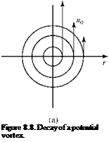
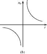
Consider a two-dimensional potential vortex at the origin of coordinates in an incom­pressible flow, as shown in Fig. 8.8a and discussed in Chapter 4. The fluid is inviscid and the velocity field is given by V = Г/2пг, where Г is the strength of the vortex.

The potential vortex continues the behavior shown in Fig. 8.8a indefinitely in the absence of viscosity. Now, imagine that at a time t = 0, a viscosity switch is turned on so that the fluid instantaneously becomes viscous, whereas nothing is done to sustain the strength of the potential vortex. A prediction of the resulting flow field requires the solution of a linear, time-dependent form of the Navier-Stokes equations.

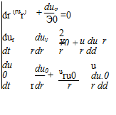
Подпись: dua dr (rur) + —0 Э0 =0 dur duv 2 ¥0 + u du_r dt r dr r r dd du0 du0 — + uru0 u du.0 dt r dr r r dd Decay of a Potential Vortex

The continuity and momentum (Navier-Stokes) equations in polar coordinates become:

Подпись: Figure 8.8. Decay of a potential vortex.
Decay of a Potential Vortex Decay of a Potential Vortex

The student should verify these equations. (Examine the equation following Eq. 3.54 and Example 3.10 but recall that both the time dependence and the viscous stresses must be retained in the present situation.) Notice that the momentum balance was divided through by the (constant) density so that the kinematic viscosity appears in the viscous terms. For the conditions specified, it is assumed that streamlines are circular (as they are in the potential vortex); thus, the radial velocity component, ur, is everywhere zero. The continuity equation reveals that the circumferential velo­city, u0, cannot be a function of 0 and therefore is a function only of time and radial

Decay of a Potential Vortex Подпись: 1A r dr Подпись: du0 dr Подпись: r

position. It also is apparent that none of the variables can depend on the angular position by symmetry. The 0-momentum equation then reduces to:

The solution of this linear equation is found by standard methods (see Exercise 8.26) to be:

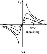
U0(r>[1 “e(f2/4vt)] (8-25)

and is shown with solid lines in Fig. 8.8c for increasing values of time. The constant of integration is expressed in the form of the vorticity, Г, for a potential vortex. Notice that when viscosity is introduced into the flow model, the infinity in flow velocity at the origin (i. e., a physical impossibility) disappears. At the origin, the viscous vortical flow exhibits solid-body rotation. As time progresses, the vortex decays and, ulti­mately, the signature of the vortex in the flow field disappears. This is the observed behavior of the vortices trailing behind the wings of an aircraft, and the disturbance eventually is smeared out by the action of viscosity. The kinetic energy originally contained in the potential vortex is dissipated by viscosity and changed into internal (i. e., thermal) energy, resulting in a (slight) increase in air temperature. In addition to being of interest because it represents an exact solution to the Navier-Stokes equations, the solution for a decaying vortex (sometimes called a Taylor, or a Lamb, vortex) is useful as an exact benchmark solution against which to validate certain CFD codes.

Notice that it was not necessary to use the radial-momentum equation to find the velocity solution. However, the radial momentum yields additional information of interest; namely, the pressure distribution through the vortex as a function of time. The r-momentum equation reduces to:

2 л

p ul = 2E, (8.26)

v r dr’

which can be integrated to yield the pressure from the known solution for the velo­city, u0. The result (refer to Exercise 8.26) shows that the pressure has minimum value at the center of the vortex (zero pressure in a potential vortex). Hence, a par­ticle trapped in the center of a vortex tends to stay there until it can overcome the radial pressure gradient.

Steady, Incompressible Flow Between Two Semi-Infinite Parallel Plates

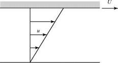
We consider two long parallel plates with a viscous fluid between them, as shown in Fig. 8.7. The fluid initially is at rest. At some time, the top plate is set in motion to the right with a constant velocity U. We are interested in the steady-flow problem—that is, after the plate has been in motion for a long time. This flow problem is called Couetteflow (see Schlichting, 2003).

With parallel flow again assumed, the defining equation is the same as Eq. 8.21. However, in the case of Couette flow, the problem is easier because no pressure difference is imposed on the flow between the two plates to make the fluid move. The fluid is moving as a consequence of the viscous force at the upper surface—it is being pulled along by the moving upper plate. Thus, there is no pressure dif­ference driving the flow, dp/dx = 0, and the defining equation for Couette flow reduces to:

d2u = d2u = о

a?=dX2 = ,

subject to the boundary conditions:

ulz = о = 0; ulz = H = u.

Integrating twice and evaluating the constants of integration using these boundary conditions, the result is a linear-velocity profile given by:

u = Hz, (8.24)

as shown in Fig. 8.7b. The student should verify this result. If a left-to-right – driving pressure difference is applied to the fluid between the two plates in Fig. 8.7, the solution to the resulting linear problem is a superposition of the

Steady, Incompressible Flow Between Two Semi-Infinite Parallel Plates

(b)


z


H


no

flow


(a)

Figure 8.7. Couette flow.

linear-velocity profile of Couette flow and the parabolic profile found previously in Poiseuille flow.

Exact Solutions of the Navier-Stokes Equations

If sufficient simplifying assumptions are available in framing a viscous-flow problem, it is possible to find an exact solution to the resulting Navier-Stokes equations. Three examples are presented in this section. In all of these examples, the Navier-Stokes equations become linear and analytical solutions are then possible. Other examples of steady and unsteady problems that permit an exact solution of the Navier-Stokes equations include the impulsively started flat plate, the stagnation-point flow, and the flow between two concentric, rotating cylinders. Detailed treatment of these prob­lems is in White, 1986 and Schlichting, 2003. In the first two examples that follow, two-dimensional airfoil coordinates (x, z) are used rather than the usual two-dimen­sional coordinates (x, y) to keep our focus on the airfoil/wing viscous-flow problem.

Steady, Parallel, Incompressible Flow Through a Straight Channel

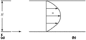
It is assumed that there is a two-dimensional steady flow through an infinitely long channel of unit width and of height H, as shown in Fig. 8.6a. It is assumed further that all flow streamlines are parallel to the solid wall (i. e., w = 0 everywhere). This limits the Re number of the problem to a small enough value so that the flow is laminar. Such a flow is sometimes called Poiseuille flow (Schlichting, 2003).

Figure 8.6. Poiseuille flow.

Because w = 0, the continuity equation, Eq. 8.19, requires that:

d – = 0 ^ u = f(z) only. (8.20)

dx

It follows that the Navier-Stokes Eq. 8.18 reduces to:

0 + 0 = -& + pdu (8.21a)

, dx dz2

0 + 0 = – І + 0. (8.21b)

Notice how the assumption of parallel flow eliminated the nonlinear convective acceleration terms on the left side of the equation. The resulting linear equations are solved easily. The z-momentum equation, Eq. 8.21b, indicates that p depends on the axial position, p = p(x) only. Eq. 8.21a then states:

Подпись: or

Exact Solutions of the Navier-Stokes Equations

dp = d2u dx ^ dz2 ’

function of | = | function of x only ) ^ z only

If the left side of the equation, which is independent of z, is equal to the right side, which is independent of x, then both sides must be independent of both x and z; namely, they both must be equal to a constant. Thus, Eq. 8.21a may be written:

d2u dp

p 2 = = constant, or

dz2 dx (8.22)

dp d2u

= constant; p = constant.

dx dz2

Notice that the pressure gradient in the streamwise direction must be constant. This is the pressure (supplied by a pump or compressor, for example) that pushes the flow in the channel from left to right. The expression, d2u/dz2 = constant, may be integrated twice. This process leads to two constants of integration that are evalu­ated by applying the no-slip boundary condition at both of the solid walls; namely:

ulz = 0 = 0 = ulz = H

The result of the integration and the application of the boundary condition is:

u=£ f(z2-(823)

where H is the height of the channel. The student should verify this result. This is the equation for a parabolic profile, as plotted in Fig. 8.6b.

Boundary Conditions for Viscous Flows

Boundary conditions are the mechanism by which a solution of a differential equation is related to a specific physical problem. Whether or not a flow is viscous, there can be no velocity component normal to the solid surface of a body. If the body surface is not solid and there is suction or blowing through the surface, then the normal component of velocity is not zero at the wall but rather proportional to the mass flow through the surface. The focus here is on solid surfaces so that one boundary condition at our disposal is that there is no flow through the solid surface (i. e., the normal component of velocity at the surface is zero).

For a viscous flow, the physically observed fact is that the tangential velocity of the flow at the body surface is the same as that of the body. If the body is in motion, the fluid “sticks” to the surface and is carried along by the body. If the body is at rest (i. e., the usual point of view for problem solving), then the tangential velocity at the body surface is zero. This is the so-called no-slip boundary condition that must be imposed on the tangential velocity at a surface in a viscous flow.

The reason that the fluid sticks to the surface is explained at the molecular level in Chapter 2 in terms of the momentum transfer between the molecules and the molecular structure of the solid surface. In effect, all momentum parallel to the sur­face is destroyed by inelastic collisions on the rough interface.

Notice the fundamental difference in the boundary condition that is imposed on the tangential-velocity component at the surface of a body in inviscid and viscous flows. If the flow is inviscid, the velocity vector at the surface simply must be tan­gent to the body without any magnitude specified (i. e., a repetition of the previous “no-flow-through-the-surface” boundary condition). However, if the flow is viscous, then the tangential-velocity component at a solid surface at rest must be zero (i. e., the no-slip condition).

Navier-Stokes Equations for Incompressible Flow

The Navier-Stokes equations for an incompressible, viscous flow may be written by simplifying Eq. 8.15. As mentioned herein, the terms containing the bulk viscosity, X, drop out when considering an incompressible flow because the continuity equation requires that:

^ + ^ + ^ = 0. (8.16) dr dy dz

Navier-Stokes Equations for Incompressible Flow Подпись: (8.17)

Also, the coefficient of viscosity, ц, may be treated as a constant because tempera­ture variations throughout the flow are very small. Thus,

These are the Navier-Stokes equations for steady, incompressible, viscous, three-dimensional flow. Notice that there are now four equations: the continuity equation, Eq. 8.16, written for an incompressible flow; and the three momentum equations in Eq. 8.17. Thus, there are four unknowns: u, v, w, and p. The density, p, is a known constant and the coefficient is viscosity, ц, is a known constant for a particular fluid.

Navier-Stokes Equations for Incompressible Flow Подпись: (8.18)

Eq. 8.16 now is written for two-dimensional flow in the x-z (or airfoil) plane. Thus, v = d/dy = 0 and Eq. 8.17 reduces to:

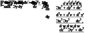
where V2 is the Laplacian operator. These are the Navier-Stokes equations for a steady, two-dimensional, incompressible, viscous flow. Rewriting the continuity equation, Eq. 8.16, for two-dimensional incompressible flow:

^ + ?w = 0. (8.19)

dx dz

This provides the third equation needed to determine the three unknowns, u, w, and p. Carefully examine Eq. 8.18. Note that even after the considerable simpli­fication of assuming an incompressible flow, the Navier-Stokes equations still are nonlinear due to the convective acceleration terms on the left side involving prod­ucts of the velocity components and their derivatives. We cannot use the powerful superposition principle that is a benefit in linear problems. There exist no general methods for integrating these equations, although exact analytical solutions exist for a few special cases that we examine carefully in subsequent sections. This sug­gests that simplifying assumptions must be applied if solutions to viscous problems are to be found. An important simplification takes advantage of the thinness of the usual viscous region, or boundary layer. The Navier-Stokes equations are found to be considerably simpler for the case of a thin boundary layer, but the resulting boundary-layer equations are still nonlinear. Before the boundary-layer equations are developed, it is useful to examine the proper boundary conditions for a viscous – flow problem.

Navier-Stokes Equations

The differential-momentum equations that include viscous terms are called the Navier-Stokes equations. Recall from Chapter 3 that the differential-momentum equation can be derived by applying the Conservation of Momentum principle (in the form of Newton’s Second Law) to a moving fluid particle. The result for two­dimensional viscous flow was Eq. 3.74. Here again, we begin by applying Newton’s Second Law to a fluid particle in Cartesian coordinates; however, the viscous forces now must be accounted for in detail. For convenience, the fluid particle is assumed to be a cube with volume (dxdydz). Because the fluid particle is of constant mass p(dxdydz):

Подпись: (8.3)D [p(dxdydz)V] = p(dxdydz) = f,

where DV/Dt for steady flow is the convective acceleration of the particle and F is the net force acting on the fluid particle.

where the right side is written as differential-force components because we are dealing with an infinitesimal fluid particle. It remains to detail the force terms on the right side of this equation. In the absence of body forces, these terms express forces (or stresses) exerted on the outside surfaces of the fluid particle by the surroundings. Recall that in addition to normal pressure forces (i. e., the only forces present in an inviscid flow), the force terms in Eq. 8.5 must include all of the shear and normal forces due to the presence of viscosity.

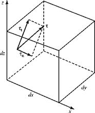
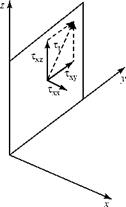
For convenience, the fluid-particle cube with volume dxdydz is assumed to be at the origin of coordinates in a snapshot of the moving particle taken at an instant of time, as shown in Fig. 8.2. In general, the surface stress, t, is at an angle with res­pect to each surface of the cube, as illustrated in the figure for the surface passing through the origin and perpendicular to the x-axis. Now, we decompose this general surface stress, t, into a component normal to the face, Tn, and a component tan­gential to the face, Tt. The component Tt can be decomposed further into two com­ponents in the coordinate directions, as shown in Fig. 8.3, where Txx = Tn.

Navier-Stokes Equations

Подпись: = dF„
Подпись: (8.4)
Подпись: (8.5a)

Figure 8.2. Differential element and general stress.

Подпись: Figure 8.3. Notation for stresses.
Navier-Stokes Equations

The following notation is used:

1. The first subscript on the symbol for stress indicates the axis normal to the plane on which the stress acts.

2. The second subscript corresponds to the direction in which the stress acts.

Navier-Stokes Equations

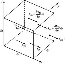
Thus, Txz indicates the stress on a plane normal to the x-axis and acting in the z-direction. Figures similar to Fig. 8.3 may be drawn for the five other planes that define the fluid particle. Fig. 8.4 indicates all of the stresses acting in the x-direction on the six faces of the fluid particle. For convenience, baseline values of the stresses are assigned to the faces in the coordinate planes. Thus, the tangential stress on the rear surface is given by:

As a matter of convention, the stresses on a plane are taken to be the force per unit area acting on the side of the plane that faces in the positive coordinate direction. Stresses acting on the outside surfaces of the element are shown with a dot • on the arrow in Fig. 8.4. Thus, the stress on the upper surface of the fluid element acts on the outside of the element in Fig. 8.4, whereas the shear stress on the lower surface acts on the inside of the surface. Likewise, Txx is a normal stress acting on the inside of

Подпись:Navier-Stokes EquationsFigure 8.4. Stresses acting on a fluid element.

the left face of the element in Fig. 8.4; hence, – t^ is a normal stress acting on the out­side of the left face of the element. Notice how this convention returns the familiar result in the case of inviscid flow. In that case, Txx = – p (see Eq. 8.13), and the normal pressure force acts toward the right on the outside of the left face and toward the left on the outside of the right face of the element. Thus, the pressure force acts on the fluid particle, as our formulation of the momentum-balance equation requires.

Navier-Stokes Equations Подпись: dxdy = 0, Navier-Stokes Equations

Using this notation and convention and taking a force (i. e., stress times area) to be positive in the positive coordinate direction, the net force acting on the element in the x-direction (for example) can be deduced. Recall that Newton’s Second Law requires this to be the net force acting on the element. Remember that a force acting on the inside of a surface represents the force of the element acting on the surround­ings, so that the direction of this force must be reversed before it is entered into the expression for Newton’s Second Law. The net force acting on the outside surfaces of the particle, Fig. 8.4, in the x-direction is then as follows:

Navier-Stokes Equations Navier-Stokes Equations Navier-Stokes Equations Navier-Stokes Equations

or, canceling:

Подпись: dFz = Navier-Stokes Equations Подпись: dxdydz. Подпись: (8.6c)

and

Notice that Eqs. 8.6b and 8.6c can be obtained directly from Eq. 8.6a by permuting the second subscript because this is the direction subscript. Also notice that dxdydz is simply the volume of the fluid particle.

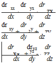
Navier-Stokes Equations Подпись: dr dr dr xx + yx + zx dx dy dz dr dr dr xy + yy + zy dx dy dz dr dryz dr xz + yz - + zz dx dy dz Подпись: (8.7)

Finally, we substitute Eq. 8.6 for the force terms on the right side of Eq. 8.5. Then, we cancel the coefficient (dxdydz) on both sides of the equation. This implies that the resulting equation is independent of the volume of the fluid particle, which is expected. The result is:

Подпись: —TПодпись:Подпись: —TПодпись: zxNavier-Stokes Equations

Подпись: z
Подпись: Figure 8.5. Tangential stresses on a fluid element.

x

These are the components of the momentum equation in three-dimensional Car­tesian coordinates. Notice that even with the help of the continuity equation, there are many more unknowns than there are equations. The fluid stresses on the right side of Eq. 8.7 must be studied further, with the aim of expressing them in terms of velocity-component derivatives. Recall that in these equations, the normal stresses (with the double subscript) consist of both pressure and viscous stresses. The mixed subscripts xy, zx, and so on denote shear (i. e., tangential) stresses. The problem of the large number of unknowns in Eq. 8.7 is alleviated by realizing that the shear stresses are not independent. Consider the tangential stresses acting on the two­dimensional fluid element in Fig. 8.5.

The tangential stresses acting on the outside faces of the fluid element are shown. If the torque about the Point 0 is not zero, the nonzero torque causes an infinite angular acceleration of the fluid element because it has infinitesimal mass. Because this cannot occur in nature, the tangential stresses must be in equilibrium such that:

Txz _ Tzx, (8.8a)

and, by a similar argument:

Txy _ Tyx; Tyz _ Tzy, (8.8b)

This reduces the number of unknown stresses to six: three shear stresses and three normal stresses. All of these viscous stresses can be related to velocity-component derivatives. How this is accomplished is discussed in two parts.

1. Shear stress. The molecular origins of shear stress are discussed in Chapter 2. Recall that in solid mechanics, the shear stress on a solid is proportional to the strain or angular distortion (i. e., Hooke’s Law). For liquid or gases, it is assumed that the shear stress is proportional to the strain rate, or to the rate of change of angular distortion of the fluid element. For air and water, this assumption has been well validated by experiment. The proportionality between shear stress and strain rate is linear for air and water; hence, they are termed Newtonian fluids. If there is a nonlinear dependence between shear stress and strain rate (e. g., as in blood), then the fluid is termed non-Newtonian. Only Newtonian fluids are considered here.

In Chapter 4, the concept of the strain of a fluid element is discussed. The rate of strain, exy, of a two-dimensional, fluid particle in the x-y plane was defined

in terms of the rate of change of angular distortion of the particle and then in terms of velocity-component derivatives, Eq. 4.3. This result in Chapter 4 was set aside for later use and is used now. Rewriting Eq. 4.3:

Подпись: (8.9) pexy, where m is a con- _ dv du £xy ~dx + dy ‘

Navier-Stokes Equations

For a Newtonian fluid, it is assumed that Txy ~ exy or Txy stant of proportionality. Thus,

The constant of proportionality, p, in Eqs. (8.10a, b,c) is called the coefficient of viscosity, and is termed a transport property of the fluid. It has different values for different fluids. The magnitude of the coefficient of viscosity may be thought of physically as being a measure of the ability of a gas/liquid to resist shear defor­mations. Since shear stress in a gas/liquid arises from molecular interactions, as discussed in Chapter 2, it may be shown from kinetic theory that the coefficient of viscosity is a function of pressure and temperature. For typical aerodynamic problems the pressure levels are such that the small pressure dependence may be ignored. Thus, viscosity may be assumed to be a function of temperature only. For incompressible flow, where any temperature excursion in the flow is very small, the coefficient of viscosity may be taken to be a constant. For air at stan­dard temperature,

M _ 3.72.10-7 slug/fts (m _ 1.78.10-5 kg/ms). (8.11)

Because the ratio р/р appears often in the analysis, it is given a special symbol and name, v _ р/р, the kinematic viscosity. At standard conditions, the kinematic viscosity of air has the value:

v _ 1.55.10-4 ft2/ s (1.44.10-5 m2/s).

Подпись: M = M b Navier-Stokes Equations Подпись: To+S T + S Подпись: (8.12)

In some applications, involving flows with large temperature variations may be necessary to account for the variations of the viscosity with temperature. For such cases, we use results from kinetic theory, such as Sutherland’s Law:

where for air:

T0 = 491.76° R (T0 _ 273.2° K)

< рb = 3.58540-7 slug/fts (pb _ 1.716.10-5kg/ms)

S = 199.8° R (5 = 111°*:).

For temperatures between 378 and 3,420° R, this expression gives values within 2 percent of the experimentally measured values. The viscosity coefficient and other physical parameters also may vary with pressure. Values of the viscosity coefficients and parameters for other gases and liquids are in Thwaites, 1949 and Hiemenz, 1911. For problems involving incompressible flow, constant values for the viscosity coefficient (e. g., those given in Eq. 8.11) are appropriate.

Navier-Stokes Equations

2. Normal Stress. In an inviscid flow, the only normal stress on a fluid particle is the pressure. The molecular origin of this pressure is discussed in Chapter 2. However, in a viscous flow, there are normal stresses present in addition to the familiar pressure stresses. This fact is emphasized by introducing the following notation:

Подпись: (8.13)

Подпись: yy

x = —p + o

yy и yy

This representation indicates that the normal stress is the sum of two parts: the part due to pressure, p (the negative sign indicates that it acts inward on the particle surface), and a second part, o, which represents normal stresses caused by viscosity. These viscous normal stresses can be significant if there are large velocity gradients du/dx, du/dy, and du/dz at the faces of the fluid particle. These effects often are neglected in aerodynamic applications because the shearing stresses are far more important.

Previously, from a macroscopic viewpoint, we described a fluid particle as being of fixed identity. However, at the molecular level, the actual particles that com­prise the fluid particle are changing continually. Because of the random motion of the molecules, some are leaving the fluid particle and others are entering. Thus, there is a continual diffusion of mass and momentum (at the molecular level) in and out through the surfaces of the particle. If there are rapid inward or outward movements of the faces of the fluid particle, this results in an unbalance of the mol­ecular diffusion of momentum across the particle boundaries in the normal direc­tions. By Newton’s Second Law, there must be a corresponding unbalanced force. It is this force that is denoted as oxx, oyy, and ozz, the normal stresses due to viscosity. Recall that the existence of a shear stress also is explained at the molecular level (see Chapter 2).

Navier-Stokes Equations Подпись: (8.14)

The derivation of the defining equations for the viscous normal stresses is pre­sented in detail in Ref. 5. Here, we simply display the results for completeness:

These viscous, normal-stress expressions contain two constants of proportionality. The constant p is the same coefficient of viscosity observed before in the shear-stress expressions. The second constant, X, is called the coefficient of bulk viscosity because it is associated with a change in particle volume. For an incompressible flow, the quantity in square brackets in Eq. 8.14 is zero by virtue of continuity, so that X does not enter into consideration of an incompressible-flow problem.

Navier-Stokes Equations Подпись: (8.15)

It remains to substitute the expressions for the shear stresses in Eq. 8.10 and the normal stresses in Eqs. 8.13 and 8.14 into the appropriate force terms in the momentum expression, Eq. 8.7. The result is:

+

+ d

du + dw л

d

dw + dv ^

dr

b

ydz dr y

>

b

,dy dz

These are the Navier-Stokes equations for a steady, compressible, three-dimensional, viscous flow.

Notice in Eq. 8.15 that the viscosity coefficients are located inside the spatial derivative. In a compressible flow, the temperature may change greatly over the flow field; hence, the temperature-dependent viscosity coefficients cannot be treated as constants. Recall that derivatives of density (i. e., p, mass per unit volume) do not appear in Eq. 8.15 even for a compressible flow. This is because the mass of the fluid particle, pdrdydz, is constant so that the mass term passes through the Eulerian derivative in the statement of Newton’s Second Law. The volume of the fluid particle then divides out, leaving the density as a coefficient of the substantial derivative.

Viscous Incompressible Flow

Подпись: 8External aerodynamics was a disturbingly mysterious subject before Prandtl solved the mystery with his work on boundary layer theory from 1904 onwards.

L. Rosenhead Laminar Boundary Layers, Oxford 1963

8.1 Introduction

This chapter examines the role of viscosity in the flow of fluids and gases. Although the viscosity of air is small, it must be included in a flow model if we are to explain wing stall and frictional drag, for example. The four preceding chapters are con­cerned with the analysis of airfoils, wings, and bodies of revolution based on an assumption of inviscid flow (i. e., negligible viscous effects). The inviscid-flow model allowed analytical solutions to be developed for predicting, with satisfactory accu­racy, the pressure distribution on bodies of small-thickness ratio at a modest (or zero) angle of attack. However, the inviscid-flow model leads to results that are at odds with experience, such as the prediction that the drag of two-dimensional air­foils and right-circular cylinders is zero. This contradiction is resolved by realizing that actual flows exhibit viscous effects.

Viscosity is discussed from a physical viewpoint in Chapter 2. In Chapters 5, 6, and 7, the existence of viscosity is acknowledged when it is necessary to advance an analytical derivation for an inviscid flow. Also, viscous effects are called on, with words like viscous drag and separation, when comparing the predicted and observed behavior of airfoils and wings. However, no analysis in this textbook has been developed thus far that provides the required detailed physical basis for these effects.

The focus of this chapter is a detailed study of the role of viscosity in an incom­pressible flow, particularly regarding modifications to the behavior of airfoils and wings that was predicted based on an inviscid-flow model. This study answers ques­tions such as: Why does a wing stall? How can stall be predicted or prevented? How is frictional drag on a vehicle calculated?

When we include detailed viscous (and, later, heat-transfer) terms in the con­servation equations of Chapter 3, it leads to a set of equations that defy analytical

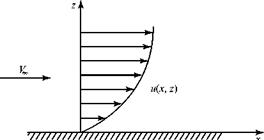
Figure 8.1. Typical velocity profile in a boundary layer.

Viscous Incompressible Flowsolution—even for incompressible flows—except in special cases. In 1904, Prandtl* showed that a very thin “boundary layer” exists on the surface of bodies immersed in a flowing medium that has a small coefficient of viscosity (e. g., air). Within the boundary layer, flow-velocity gradients are large, whereas outside of the boundary layer, they usually are small (Fig. 8.1). Recall from Chapter 2 the argument at the molecular level that the velocity at the wall must be zero. This is termed the no-slip boundary condition.

Recall also from Chapter 2 that the velocity changes from the freestream value are the net result of mixing at the molecular level. This mixing leads to a shear stress in the fluid. Shear stress in a flow is proportional to velocity gradient, as discussed later. Thus, within the thin boundary layer, shear forces dominate, whereas outside of the boundary layer, inertial forces (due to directed motion of the fluid particles) dominate. This allows the problem of flow around a vehicle to be decomposed into two parts, both of which are treated simply by approximate equations appropriate to either an external inviscid flow or a thin viscous boundary layer.

Because the boundary layer is thin, the problem of flow around a vehicle first is treated as if there were no boundary layer present (i. e., inviscid-flow model). Problems in which the viscous layer is not thin (e. g., airfoils beyond the stall) are excluded. The boundary-layer problem is solved next, and then the two solutions are synthesized (i. e., combined) to describe the entire flow field. The pressure distribution arising from the external-flow solution is used as a known in the bound­ary-layer solution, as shown later. Iterations are carried out to account for the small modification to the body shape caused by the presence of the boundary layer.

Alternatively, numerical finite-difference (i. e., CFD) solutions have been devel­oped that can treat the entire flow field in one unified manner and the external flow and the boundary-layer flow need not be decomposed. Such CFD solutions are complex and make strong demands on computer capability. The CFD methods are numerous and the mathematical theory is beyond the scope of this textbook, but we use the simpler concepts to demonstrate the power of such methods and to obtain useful solutions. We begin here by examining many simpler analyses to introduce several concepts that are applicable to all viscous flows.

For streamlined bodies in an incompressible flow, boundary-layer behavior depends on the value of a nondimensional parameter Re, the Reynolds number, which was introduced in Chapter 2:

Re = £Yk, (8.1)

M

Ludwig Prandtl (1875-1953) was a German professor of applied mechanics whose concept of the boundary layer was a breakthrough in the study of viscous flow.

where p is the density, V is the velocity, ц is the coefficient of viscosity, and L is a characteristic length such as a wing chord. This ratio was described in a discussion of similarity parameters, Eq. 2.20. The Re number usually is evaluated at a con­venient reference condition such as the freestream, and it is the most important parameter that influences the characteristics of any viscous flow. If the flow problem involves compressibility, then an additional parameter—the Mach number—must be accounted for in the mathematical modeling.

If all of the streamlines in the flow within the boundary layer are parallel to one another, the boundary-layer flow is said to be in laminas, or to be laminar. In this case, momentum is transported normal to the lamina only by molecular diffusion. If the flow within the boundary layer has a random structure and contains large eddies, then the boundary layer is said to be turbulent. In the turbulent case, momentum is carried across streamlines by convective effects resulting from random fluctu­ations of the fluid. Laminar and turbulent boundary layers each have distinctive properties and methods of solution. Both types are discussed in this chapter.

Both analytical and numerical solutions to incompressible viscous-flow prob­lems are discussed herein. These solutions primarily apply to boundary-layer flows and lead to methods for predicting the following characteristics of an incompressible boundary layer:

1. Profile. The shape of the velocity profile within the boundary layer, from the sur­face of the body to the edge of the layer, must be determined. Knowledge of this profile shape then allows the prediction of skin friction and, thus, frictional drag of a flight vehicle.

2. Growth. The boundary-layer thickness increases with increasing downstream dis­tance along a vehicle surface. The rate of growth of the boundary layer must be found if, for example, it is desired to locate an engine inlet near a vehicle surface but out of the boundary layer so as to avoid ingesting nonuniform boundary-layer flow into the engine. This “growth” may be negative in regions of highly acceler­ated flow.

3. Separation. Under certain circumstances, the flow in the boundary layer leaves the body, or separates. When this occurs, the apparent shape of the body, as seen by the oncoming flow, changes dramatically and the oncoming flow no longer per­ceives a streamlined body. This may have drastic consequences (e. g., wing stall); thus, it is important to determine which parameters influence separation and how separation effects can be minimized or avoided. Separation occurs primarily when the flow is decelerating.

4. Transition. * A boundary layer usually starts to develop at the leading edge of a body as a laminar boundary layer. Farther downstream, it may begin to “tran­sition” into a turbulent profile. This does not occur instantaneously but rather over a streamwise distance. Because turbulent boundary layers cause higher skin friction (and heat transfer) than laminar boundary layers in the same external conditions, it is important that designers have knowledge that allows prediction of the transition location, as well as an understanding of how to delay or prevent transition.

* This term is often confused with separation. It is important that the student clearly understands the meaning of these two terms.

The chapter begins by detailing the viscous terms in the Conservation of Momentum equations (see Chapter 3), which were written in symbolic form when the equations were derived originally. The momentum equations, with all of the vis­cous terms specified, are called the Navier-Stokes equations[25]. Following a discussion of the no-slip boundary condition, exact solutions of the Navier-Stokes equations for incompressible flow are reviewed. Unfortunately, the practical application of these solutions is severely limited, so approximate equations (i. e., the boundary – layer equations) are derived next.

Analytical and numerical (i. e., CFD) solutions to these laminar boundary-layer equations are carried out assuming incompressible flow. These solutions then are examined to interpret the observed behavior of airfoils and wings. Finally, tran­sition of the boundary layer from laminar to turbulent is discussed, and turbulence is introduced. The steady flow of an incompressible fluid with negligible body forces is assumed throughout the discussion.

There is no need to discuss anything further regarding the continuity equation because it contains no force (i. e., viscous) terms. Thus, the continuity equation is the same whether the flow is assumed to be inviscid or viscous. The differential con­tinuity equation was developed in Cartesian coordinates as Eq. 3.53, which for a steady, incompressible flow is:

du dv dw _ ,0

tt – + t – + ^- = 0, (8.2)

dx dy dz

where the local velocity components are u, v, w.

In an incompressible viscous or inviscid flow, the variations in density and tem­perature are so small that the energy (and state) equations may be set aside (i. e., uncoupled). Thus, solutions are sought here for a set of partial-differential equations consisting only of the continuity and momentum equations.

Numerical Methods

There are two classes of axisymmetric flow problems that are treated numerically: (1) the direct problem of finding the flow about a body of given shape, which may be solved by using a distributed singularity along the body axis or a panel method; and (2) determining a body shape that results in low or minimum drag. This can be accomplished by using two different approaches. The first is to consider an inverse problem: Find the body shape that gives a desired pressure distribution on the body. The pressure distribution, in turn, is chosen so as to reduce or minimize the friction and pressure drag due to the boundary layer growing on the body surface. The second approach uses optimization algorithms and seeks to optimize the body shape for min­imum drag subject to certain constraints. A brief discussion of each method follows.

1. The direct problem: What is the surface-pressure distribution for a body of spec­ified shape?

(*-*p)

>/(*-*0)2 + r2

Подпись: V(^ r) Подпись: 4n Numerical Methods Подпись: (7.38)

(a) Distributed singularities along the body axis. We first derive an expression for the stream function in axisymmetric uniform flow due to a distributed source along the x-axis. We begin by generalizing Eq. (7.35) to represent the superposi­tion of uniform flow and a point source located at x = x0. Thus,

Подпись: dy( x, r) Подпись: b(£)d£ j _ (x- £) 4n |_ V( x-E)2 + r2 Подпись: (7.39)

where Л is the strength of the source. Next, we consider a source distributed along the x-axis between x = 0 and x = L. We rewrite Eq. 7.38 to describe a dif­ferential contribution to the stream function at a field point (x, r) due to a differ­ential length, d£ , of that distributed source located at E = x:

where p(E) is the local strength of the distributed source per unit length.

_! J b(£)(*~ £)<*£ + r2

4E)+r2 2 ‘

Подпись: V(x, r) Подпись: (7.40)

Now, we sum the contributions to the stream function at (x, r) due to all of the differential lengths of distributed source between x = 0 and x = L. We let the distributed source represent a closed body of revolution, where L is the length of the body. Summing by integration:

The first term in the square brackets in Eq. 7.39 vanishes on integration because if the body is closed, the net source-sink strength over the length of the body must be zero. Thus, L

J b(E)d£ = 0.

Numerical Methods Подпись: 1 ду; r dr ’ Подпись: 1 Эу r д X Подпись: (7.41)

Recall that by definition, Eq. 7.30, the expressions for the velocity components ux and ur follow from the expression for the stream function by differentiation namely:

In Eq. 7.40, the integration is relative to the variable E so that the integrand may be differentiated directly. If p(x) is represented as a polynomial, then the inte­gral expressions for у, Eq. 7.40, and for ux and ur, Eq. 7.41, may be evaluated in closed form.

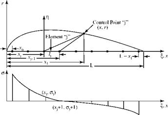
Following Zedan and Dalton (1978), the source-strength distribution along the x-axis is split into N segments, each of length ALj, and Eq. 7.40 is expressed as a summation. Zedan and Dalton, 1978 considers a linear-source distribution over each segment; this is generalized to a polynomial distribution in Zedan and Dalton, 1980. Figure 7.13 illustrates an assumed linear variation over each segment.

Notice that the source-strength variation is assumed and known but the mag­nitude of the strength is to be found. Referring to Fig. 7.13, let there be N source segments used to represent the body of revolution and let the strength distri­bution in each segment be of the following form:

PE = (a + bE),

where a, b are constants to be determined. The parameter E is the local axial coordinate over each segment ALj.

Подпись: Figure 7.13. Representation of a body of revolution by discrete linear segments (Zedan and Dalton, 1978).
Numerical Methods

With two constants a, b to be found for each of N segments, there are 2N unknowns. We next require that the source distributions are continuous at the junctions of the segments (i. e., there cannot be any step in source strength from one segment to the next). If there are N segments, then there are (N-1) junctions. Thus, the demand that the strength distribution be continuous at each juncture results in (N-1) equations involving the 2N unknowns, leaving (N+1) equations to be generated if the a, b unknowns are to be found and the source-strength distribution along the axis determined.

where Aij is a matrix that is a function only of the known body geometry (see Zedan and Dalton, 1978), p, is the source intensity at the jth juncture, and r = R on the surface. The closure condition, which states that the net efflux of all of the source-sink elements must be zero, supplies the final equation required; namely:

N N A Lj

1 N

= — У

i(*T) 4n f-1

X"1 л Т/ *i

У Aj V~—

j = 1 2 _

Подпись:

Numerical Methods

(7.43)

where Qj is the mass efflux over the jth source-sink segment.

As noted in previous discussions, the body surface must be a streamline, meaning that on the body surface ¥ = constant and, for convenience, ¥ = 0. Set­ting ¥i = 0 in Eq. 7.42 at N control points on the body surface results in a system of N linear-algebraic equations in (N+1) unknowns pj. The addition of the clo­sure equation, Eq. 7.43, provides the needed additional equation. Solving this set of equations provides the values of the source strength, pj, at the juncture points of the source distribution.

Numerical Methods Numerical Methods Подпись: + V Подпись: (7.44)

Now, using Eq. 7.41, the expression for the axial-velocity component at the ith control point follows from Eq. 7.42 as:

where Bjj is a matrix that is a function only of the known body geometry (Zedan and Dalton, 1978). Because the source strength pj was found in the previous step, the axial-velocity component ux is determined at each control point on the body surface.

Tangency requires that ux/ ur = dR / dx at the body surface, where R(x) is known. Hence, the radial-velocity component, ur, is determined at each control point. Lastly, Vt2 = ul + иГ and the tangential velocity, Vt at each control point is found. The surface pressure on the prescribed body follows directly from the Bernoulli Equation and the direct problem is solved.

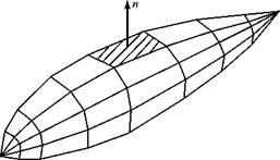
(b) The panel method. The direct problem also may be analyzed numerically by distributing singularities over the surface of a given body. This is simply the panel method discussed in Chapter 6; again the surface singularities may be sources, doublets, or vortices. We restrict the discussion here to surface sources because we are considering bodies of revolution at zero angle of attack. As before, flat quadrilateral surface panels approximate the given body, as shown in Fig. 7.14. Notice in what follows that the panel method is a three-dimensional problem even for a body of revolution at zero angle of attack because each source panel affects the flow at all other panels present in three-dimensional space.

Figure 7.14. Representation of a body of revolution with flat panels.
Numerical MethodsNumerical MethodsIn contrast, solution methods using source distributions along the body axis are formulated in cylindrical coordinates and use axisymmetric-flow equations. Thus, the panel method has an advantage over the distributed-source method in that the former can be extended to fuselage shapes that are not bodies of revolution.

Подпись: ф(Р) Подпись: _Л 1 4п [(x-Z)2+(y-n)2 + (z-<АГ Подпись: A _L 4 n PQ Подпись: (7.45)

The velocity-potential expression valid for a three-dimensional source may be derived analogously in Cartesian coordinates to the way in which the stream function was derived previously in this chapter. The velocity potential at Point P (x, y,z) due to a point source of strength L located at Point Q(£,n, Z) is given by:

where PQ is the distance between Points P and Q. This solution of the potential equation may be superposed with another solution representing a uniform flow from infinity, ф( x, y, z) = x.

Now, we assume that instead of being a point source, the source has a strength p per unit area, which is distributed over a differential panel area dA. The source distribution may be assumed to be constant over the surface, Aj, of a quadrilat­eral panel, or a higher-order distribution over the panel surface may be used. Then, the velocity potential at Point P due to the superposition of a uniform flow and a distributed source on Panel Q is given by:

Jf^ A

A 1

ФА y, z) = Vjc – j——- =. (7.46a)

4n PQ

Assuming that the source distribution per unit area is constant over any quadri­lateral panel, AJ, Eq. 7.46a simplifies to:

Ц і A.

ф( x, y, z) = yMx – 1-=L. (7.46b)

Next, we assign each panel a control point located at the middle of the panel and let the body of revolution be represented by N panels. Then, the velocity potential at the control point on the ith panel, p (x, y, z), due to the influence of the constant – strength sources on all of the N panels plus the influence of the freestream, is:

Подпись: -LІ+ФІ. .. 4n j = 1PQ lj=1
Подпись: (7. 47)
Подпись: Ф.(Х, y,z) = Vjc

Notice that the term j = i is excluded from the summation. When j = i, the behavior of that term in the series is singular because the source panel Q is the same panel as that where Point P is located, and PQ = 0 Thus, this term must be treated in a special way, as indicated by the separate term ф|j=1 in Eq. 7.47. Notice that all of the source panels contribute to the potential at a given con­trol point, even the panels on the opposite side of the body from the control point. This is the same behavior that we observed in the case of vortex rings representing a finite wing. Also, we note that the effect of a source at a control point does not depend on the distance between the source panel and the control point as measured along the body surface; rather, the effect is dependent on the straight-line distance between the two, PQ.

Taking (Эф / dn) in Eq. 7.47, where n is the unit outward normal at each con­trol point, yields the velocity component normal to the panel at each control point. According to the surface-tangency-boundary condition, each normal component of velocity must be zero. Applying this boundary condition at each control point, in turn, yields a system of N linear-algebraic equations for the N unknowns, ^j. When the source strengths are determined, the magnitude of the tangential velocity at each control point may be found and, hence, the surface pressure, after an appeal to the Bernoulli Equation. Thus, the pressure distribu­tion over a body of revolution is determined. This pressure distribution may be integrated to obtain forces, if desired.

A comparison of results using axial and surface singularity (i. e., panel) methods for inviscid flow can be found in D’Sa and Dalton, 1986. Here, we conclude that the accuracy of the method using singularities distributed along the axis of sym­metry and the accuracy of the panel method using singularities distributed over the body surface are comparable for problems involving smooth bodies. For bodies with sudden changes in curvature, the panel method is more accurate. A boundary-layer code must be appended to both of the solution methods for the direct problem to obtain the drag of the body of revolution.

2. The optimum body-shape problem: Find the body shape that has low or min­imum drag in a given application.

(a) The inverse method. This method seeks to answer the “optimum” body-shape question by focusing on the behavior of the boundary layer because it causes the drag. Thus, if a pressure distribution is specified along a body surface with the aim of generating low drag due to viscous effects, what body shape is needed to obtain this pressure distribution? Tailoring the shape of a body of revolution to achieve a low-drag boundary layer is attractive because, as noted previously, the fuselage drag comprises a ma. or fraction of the total drag of a flight vehicle. The viscous boundary layer is discussed in detail in Chapter 8; suffice it to say here that a laminar boun­dary layer is preferred to a turbulent layer because the former exhibits a much smaller skin-friction drag. The boundary-layer solution code used in conjunction with body-shape tailoring is, of necessity, complex. It must be

able to provide results for both laminar and turbulent boundary layers and it should be able to predict transition (i. e., the laminar boundary layer becomes turbulent) and separation (i. e., the boundary layer leaves the body surface). Either surface-panel or axial-singularity methods may be used in the inverse problem; both are iterative in nature. The axial-singularity method, dis­cussed herein, often is used in practice because it is computationally more efficient than panel methods in this application. In any case, the goals are to (1) achieve a strong favorable pressure gradient (dp / dx < 0) over the front portion of the body of revolution to delay transition, thus reducing frictional drag; and (2) to minimize the adverse pressure gradient (dp / dx > 0) over the afterbody so as to delay boundary-layer separation and thereby reduce pressure drag.

Zedan and Dalton, 1978 and Zedan and Dalton, 1980 discuss an iterative inverse method for finding an axisymmetric body shape with low drag. Again, the basis of the method is a source singularity distributed in N segments along the body axis, (see Fig. 7.13). In Zedan, 1978, the distribution over each segment is linear, whereas in Zedan and Dalton, 1980, the distribution over each segment is represented by a polynomial. Zedan et al., 1994, treat the problem by using a doublet singularity distributed linearly over several segments along the body axis.

The solution method begins similar to the solution of the direct problem. Following (Zedan and Dalton, 1978) the linear-source-strength distribution over each segment shown in Fig. 7.13 is represented by = (a + b£).

Numerical Methods Numerical Methods Подпись: 2 Подпись: (7.48)

With N segments of sources and two unknown constants describing the linear distribution of source strength over each segment, again there are 2N unknowns. By appealing to the continuity of source-strength distribution at each of (N-1) junctures between segments, the number of unknowns is reduced to (N+1). The (N+1) source strengths are found by writing a set of N linear-algebraic equations at N control points, Eq. 7.42, plus one closure condition, Eq. 7.43. This is the same methodology used pre­viously in the axial-source-distribution method for the solution of the direct problem. Thus, rewriting Eq. 7.42 for the stream function at each control point i:

and rewriting the closure equation, Eq. (7.43):

N ALj

Xjp£ (№ = 0. (7.49)

J = 1 о s

Подпись: u Numerical Methods Подпись: (7.50)

Again, the axial-velocity component at the ith control point is found by differ­entiation of Eq. 7.48; namely:

where A1j and B1j are matrices that are a function only of body geometry (Zedan and Dalton, 1978).

The iterative solution to find the body shape corresponding to a prescribed pressure (i. e., velocity) distribution proceeds as follows:

Подпись: (1) (2) (3) (4) Подпись: (5)Make an initial guess at the body shape, R°(x). This may be a body shape known to have a low drag for which improvement is sought or it may be a baseline ellipsoid shape.

Calculate matrices Ay and By for this geometry.

Select i = N control points on R°(x). Then, at each control point, calculate dR/dx.

Impose a pressure distribution on the assumed initial body shape. For example, to delay boundary-layer transition, this might be a pressure dis­tribution that has a stronger favorable pressure gradient over the fore­body than that exhibited by the low-drag body shape that was used as a first guess. The imposed pressure distribution is changed easily to an imposed velocity distribution through use of the Bernoulli Equation. The velocity calculated in this way is an imposed tangential velocity at each control point.

Require flow tangency at each control point on the body surface. Thus,

UL = dR

ux dx

Recalling that:


і+І

Ur


V2 =u2+


Vt = u


the tangency condition at each point i on the body surface may be written as:

Vt

1 + (dR / dx)2


Numerical Methods

Подпись: (6)Подпись: (7)With ux corresponding to the imposed pressure distribution now known from Step 5 at each control point, write Eq. 7.50 as a set of (N) linear-algebraic equations in terms of (N+1) unknown source strengths, Pj. The remaining equation for comes from closure, Eq. 7.49. Solving this system yields the source-strength distribution Pj at the juncture points corresponding to the R° body shape but with the imposed velocity distribution.

Write Eq. 7.48 on the body surface by setting ^ = constant = 0 at each con­trol point. With pj and Ay known, a new body shape is found by solving the resulting equation for R;; namely:

Подпись: Ri =-1 Vі л

2п V J AjUj.

Notice how the two different descriptions of the body surface—flow tan­gency and у = constant—are used to set up the iteration.

The body radius from Step 7 represents an improved body shape, R1. Use this in Step 1 and calculate the new matrices in Step 2. Then, repeat the iteration until satisfactory convergence is achieved. The final result is a body shape corresponding to the imposed pressure gradient.

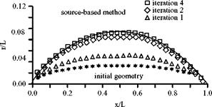
reference profile


Figure 7.15. Body profile calculated by source-based inverse method (Zedan et al., 1994).


Numerical Methods

Figure 7.15 shows a body generated by the source-based inverse method dis­cussed previously for the case of a shape with a known solution. The converged shape closely matches the reference profile after only a few iterations. Zedan, 1978, point out that this method fails for a body geometry that has an inflection point. An alternative plan is presented for this special case.

The drag of the body shape given by the iterative solution is found by per­forming a viscous-flow solution for a boundary layer growing on a surface in the presence of the prescribed pressure gradient. Running a few solutions provides a good physical idea of what is happening and a physical basis for a drag-reduc­tion strategy.

(b) Mathematical optimization techniques. These techniques require a large number of numerical calculations. Parsons et al., 1974 present a computer – based optimization procedure for generating low-drag hull shapes useful for hydrodynamic applications. The method incorporates a parametric body description, a drag computation, hydrodynamic constraints, and an optimi­zation scheme in the form of a computer program. Lutz and Wagner, 1998, describe an optimization scheme that uses a segmented linear distribution of sources along the body axis, much like the inverse method discussed herein. However, the source strength is used as a variable for the optimiza­tion process. This indirect method is combined with an integral boundary – layer method and an optimization algorithm. The focus of their work is on airship applications. The objective is to minimize the drag of the hull for maximum hull volume (i. e., lifting capacity) at different speeds (i. e., different Re number values). The student is referred to the literature for details of these and other optimization methods.

7.3 Numerical Methods for the Complete Airplane

Panel methods also are used to solve for the flow around a complete airplane. Such a solution furnishes the inviscid-flow pressure distributions on the various airplane components and predicts the forces and moments on the vehicle in an inviscid flow. Thus, the results are most useful for flight vehicles in cruise or without large separated-flow regions. The interference effect between a wing and a fuselage and in a wing/fuselage juncture also may be studied by using these numerical solutions. That is, the flow around a vehicle component in isolation is

Numerical Methods

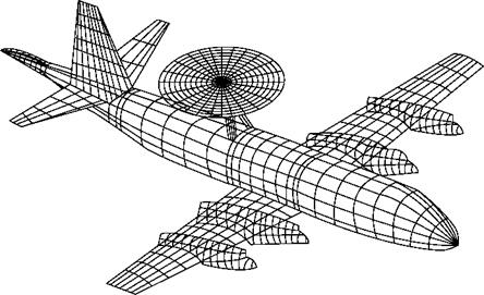
Figure. 7.16. Surface-panel configuration for a complete airplane (Tinoco, 1990).

not identical to the flow around that same component when the component is in proximity to another body in the flow. The aerodynamic characteristics of an airplane, then, are not simply the sum of the aerodynamic characteristics of all of its parts. In numerical solutions for a complete airplane, source or doublet panels usually are used to represent the fuselage, and the lifting surfaces are analyzed by the VPM or the VLM.

A panel representation of a complete airplane is shown in Fig. 7.16. The objec­tive of this computer simulation was to guide the positioning of the large radome so that the aerodynamic center of the aircraft was unchanged.

Singh et al., 1989 describe a calculation method for finding the potential flow around a complete aircraft configuration. The fuselage is represented by sources distributed along the wetted surface, whereas the wing and wing-like components are modeled by using source and vorticity distributions on their respective mean – camber surfaces. Boundary-layer effects are not included.

The aerodynamic behavior of a complete subsonic transport and partial-model results for the same transport (i. e., results for wing alone, tail on/off) are found by using a panel method and discussed by Troeger and Selby, 1998. Code VSAERO, which uses piecewise constant source and doublet singularities distributed on flat, quadrilateral panels, is used for the computations. The results are compared with experimental data, and it is found that discrepancies between analysis and experi­ment are caused primarily by viscous effects, which are ignored in the panel method. The model of the complete transport uses 3,655 surface panels for the vehicle and 2,133 wake panels.

As mentioned previously, CFD is being used more frequently in the field of aerodynamics and is of great value as a wind-tunnel partner in the solution of many complex flow problems. Recently, CFD has made increasingly larger contributions to the aircraft-design process; this evolving role of CFD is discussed by Tinoco, 1998 and Dodbele et al., 1987. The student is encouraged to read the literature on this fascinating application of numerical methods.

Flow Past a General Body of Revolution

The approach outlined in Section 7.9 may be extended by distributing increasingly source-sink pairs of finite strength inside the body or along the body axis. The sum of the source and sink strengths must be zero if the body is to be closed. Simple body shapes may be treated in this way; however, solutions for body shapes of practical interest are necessarily numerical in character. If it is required to find the pressure distribution on a suitably slender body of revolution, then an approximate analytical solution may be found that uses source singularities distributed along the body axis. The velocity potential for a uniform flow superposed with a source distributed along the body axis from to x2 is expressed as follows (see Karamcheti, 1967):

Flow Past a General Body of Revolution(7.37)

where Д£) is the source strength per unit length, /(^)d^ is the infinitesimal source strength at x = x, and the point (x, r) is a field point in cylindrical coordinates as shown in Figure 7.11. The student may verify that this expression for the velocity potential satisfies the Laplace’s Equation. Also, study the derivation of an analogous expression for the stream function that is carried out in Section 7.11.

Using Eq. 7.37 and applying the tangency-boundary condition at the surface of a given body leads to an integral equation for the unknown source-strength distri­bution, /(^). Rather than directly solving this integral equation for the source-strength distribution, it is assumed that the slenderness ratio, e, of the body is small, where e = [(maximum body radius)/(body length)]. For small e, the integral operator con­taining /(^) can be expanded asymptotically in a power series (Wang, et al, 1985). It then may be shown that the source distribution, /(x), as well as the values of x1 and x2, can be related to the axial distribution of the body cross-sectional area, S(x). When these expressions are used in Eq. 7.37, the result is an asymptotic expansion for the velocity potential, which is expressed in terms of a simple geometric property, S(x), of the body. The velocity components on the body surface and, hence, the inviscid- flow pressure distribution follow directly by definition. A similar approach for slender axisymmetric bodies in a supersonic flow is discussed in compressible flow text books.

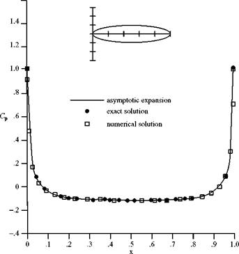
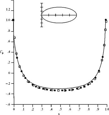
Figure 7.12 shows the pressure coefficient on the surface of an ellipsoid as evalu­ated by an exact analytical solution and by a numerical solution. Also shown in this figure (i. e., the solid line) is the pressure coefficient as calculated from the approxi­mate velocity potential obtained by using the asymptotic approach discussed previ­ously. Notice that when the body is slender, e = 0.10, the approximate solution agrees

r

Подпись: (x, r) Fig. 7.11. Coordinate system and continuous source distribution.
Flow Past a General Body of Revolution

1.6


(a) є = 0.10


1.4


(b) є = 0.20


Figure 7.12. Cp for ellipsoid of revolution, S(x) = 4x(1-x) (Wang et al., 1985).


Flow Past a General Body of RevolutionFlow Past a General Body of Revolution

well with the exact result, whereas for a body that is not so slender, e = 0.20, the asymptotic solution does not predict the exact result as well.